Tamiya Leopard 2A6 Project
Page 2: Building the Transmission
I often find the transmission
to be the most interesting part of a model build, and this is no
exception. Even though this transmission does
not have multiple gear ratios, it has other qualities which make it
different from most traditional gearboxes.
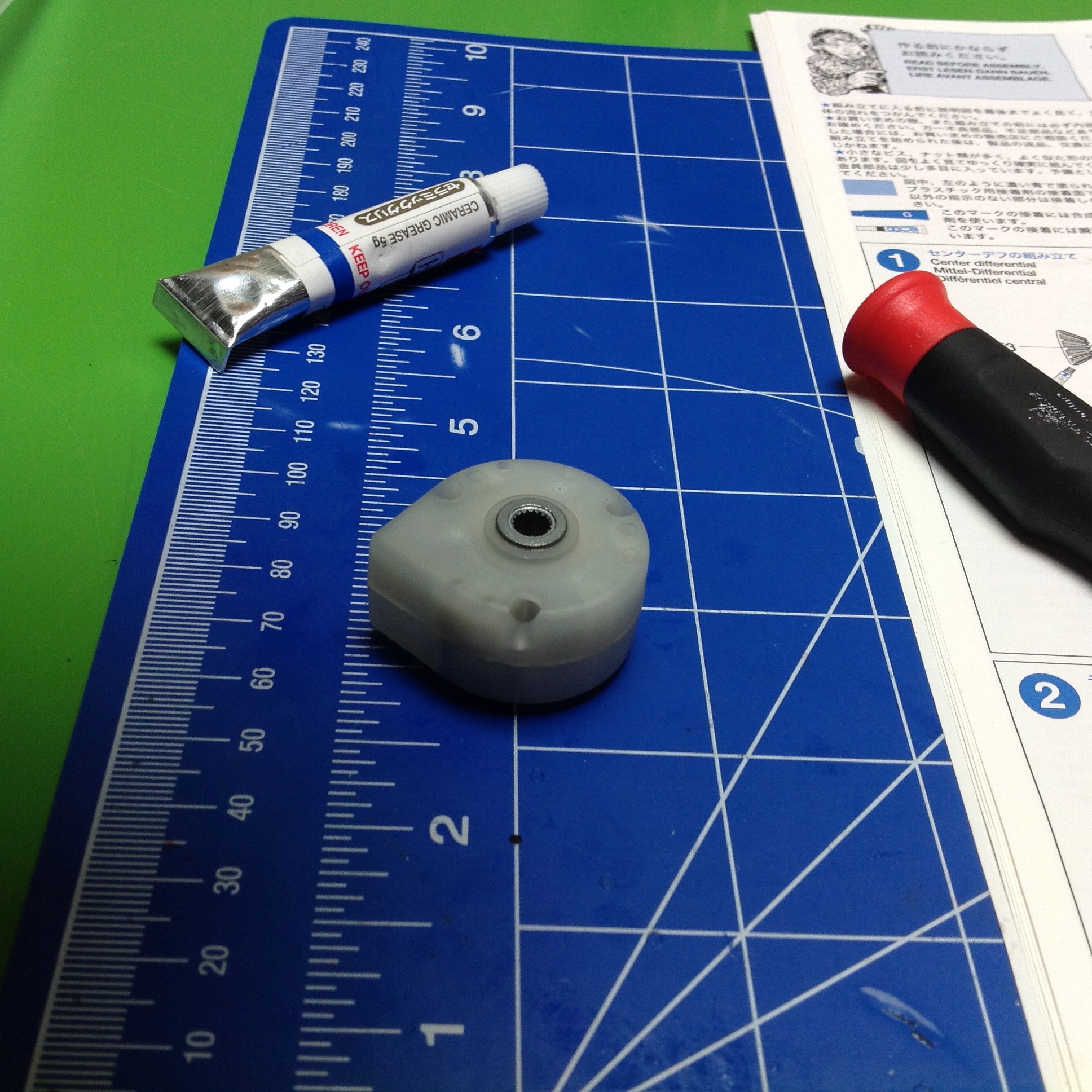
Step 1 starts right off with the transmission. This step is
entitled "center differential" but that's a bit of a misnomer.
This can't properly be called a differential because it has no ring
gear, therefore it has only 2 inputs/outputs rather than 3. It is
really just a 1:1 reversing gearbox. What goes in one side comes
out the other in the opposite direction of rotation. On the other
hand, the housing is prevented from rotation so you could think of it as
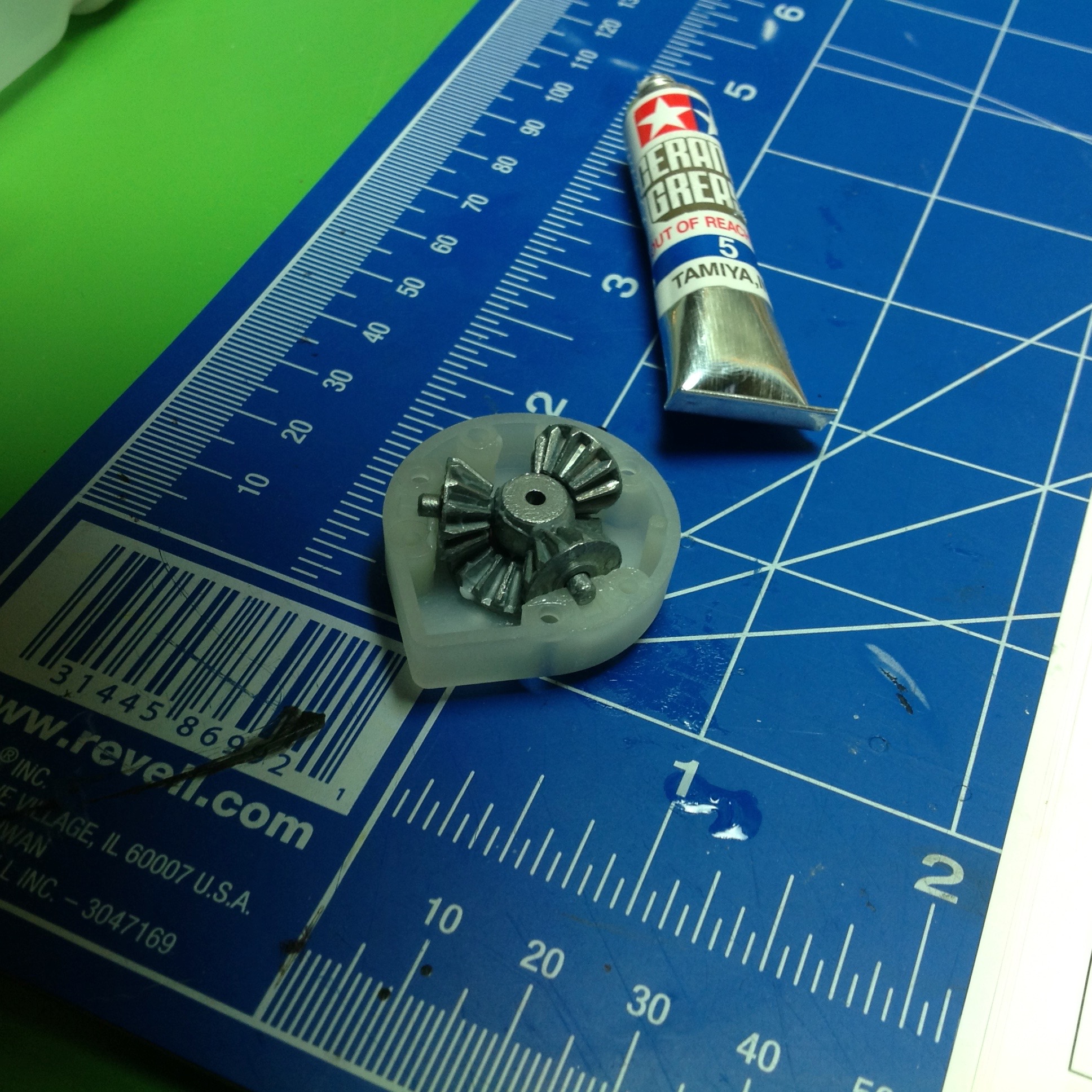
a locked ring gear. The parts inside are the same as a standard
differential and include two bevel gears and 3 pinions on a
carrier. The gears need to be lubricated with the included ceramic
grease. The housing appears to be made from a fiber reinforced
Nylon, the same material used for the plastic gears.
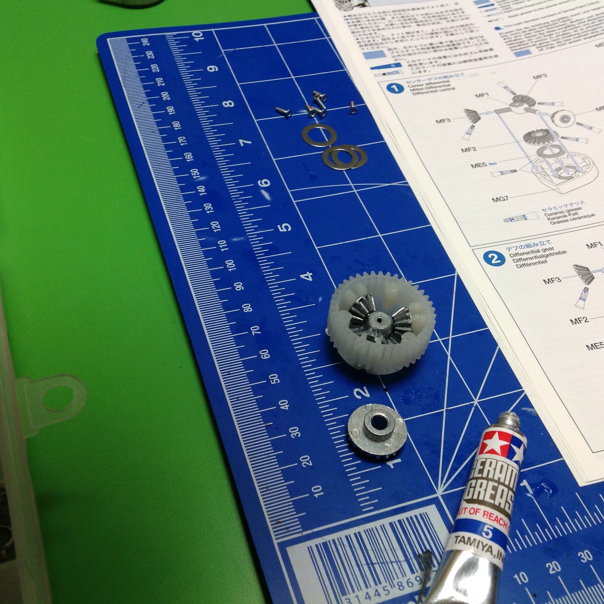
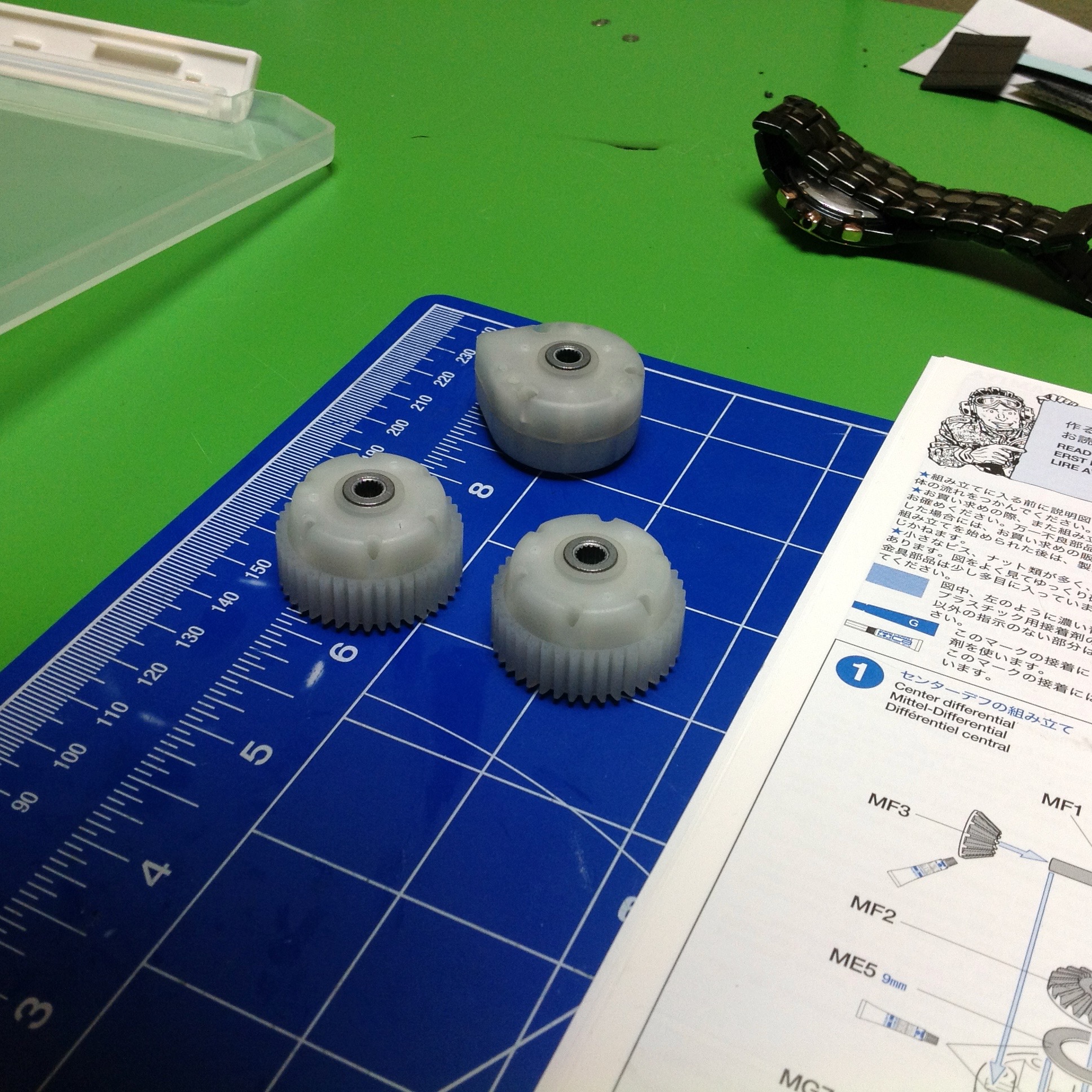
Step 2 builds a matched pair of outer differentials, this time the real
thing. The parts inside are the same as the center diff, but the
outer housing includes a spur ring gear. The bevel gears on either
side have an integral internal spline which is used to pass torque into
and out of the differential. Splined axles will plug into these.
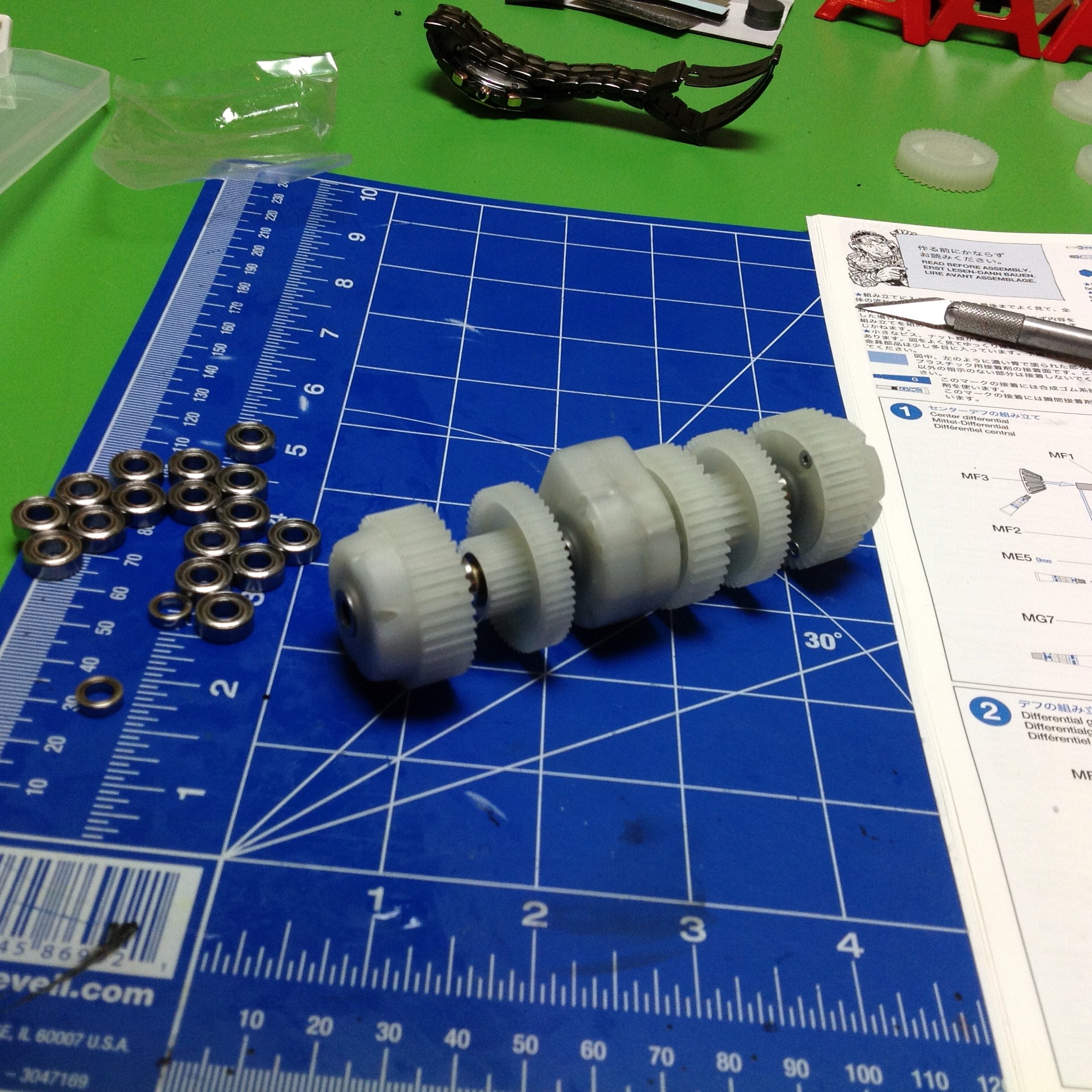
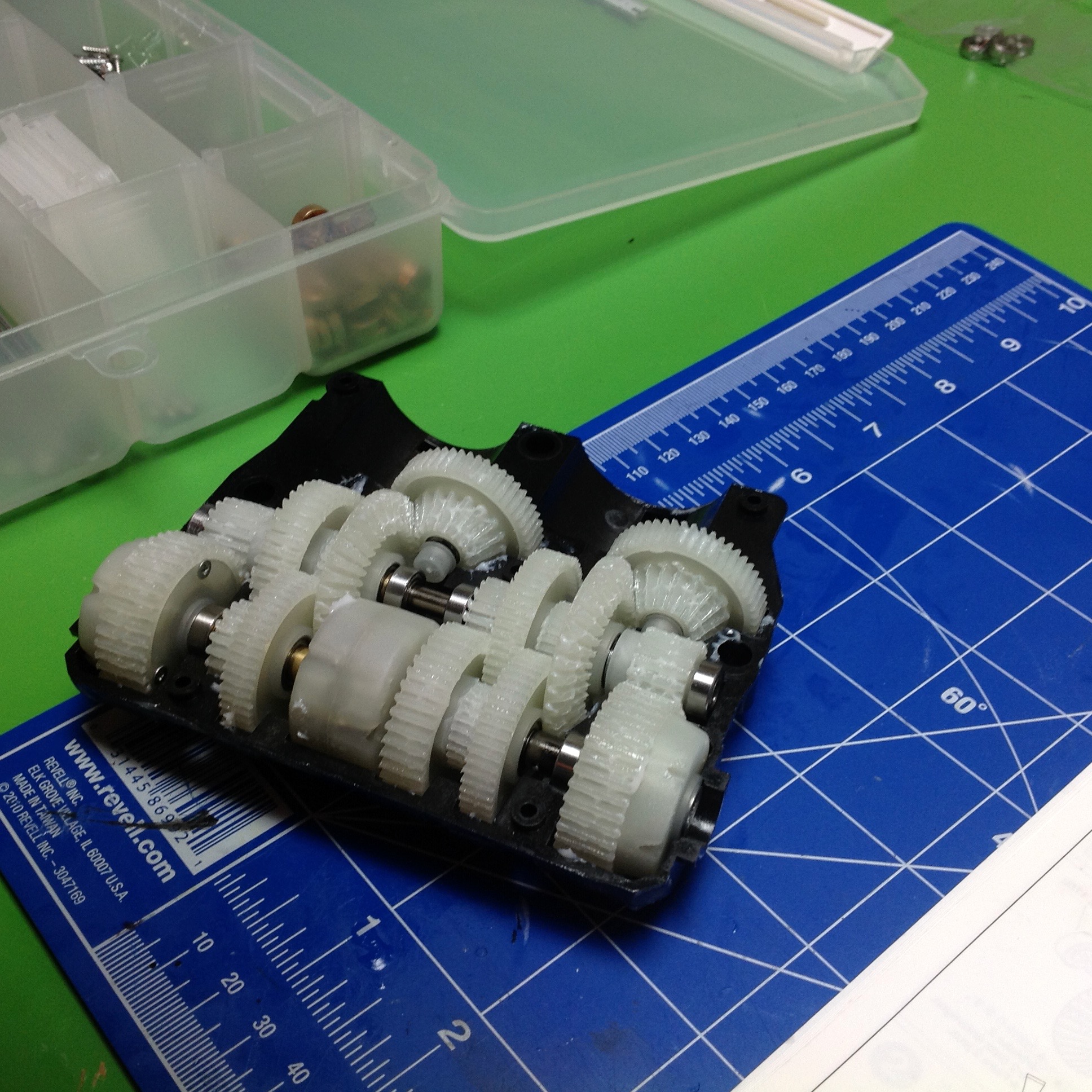
Now things start getting interesting. Step 3 combines all the differentials onto a common axis. Note that I said axis, not axle.
There are two axles, one coming out either side of the central diff
which spin opposite directions. The center diff is indexed so it
cannot spin within the transmission housing. The additional spur
gears you see between the differentials ride on ball bearings and
therefore are not locked to the axle. They are effectively idler
gears.
In the background you can see a pile of ball bearings. This kit
comes with a partial supply of ball bearings, including everything
inside the transmission. In other places on the model, metal
bushings are used. These will be discussed when we get to them.
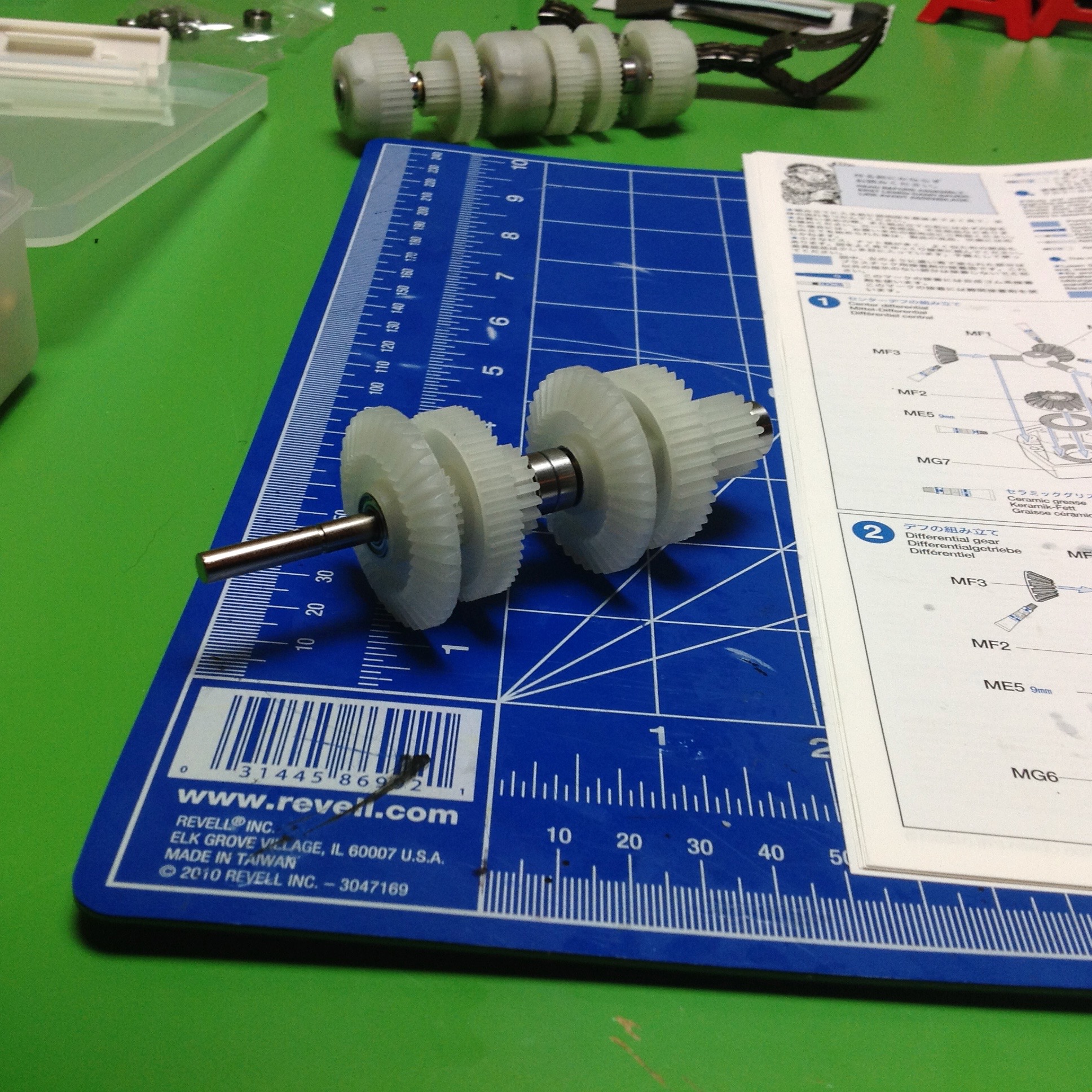
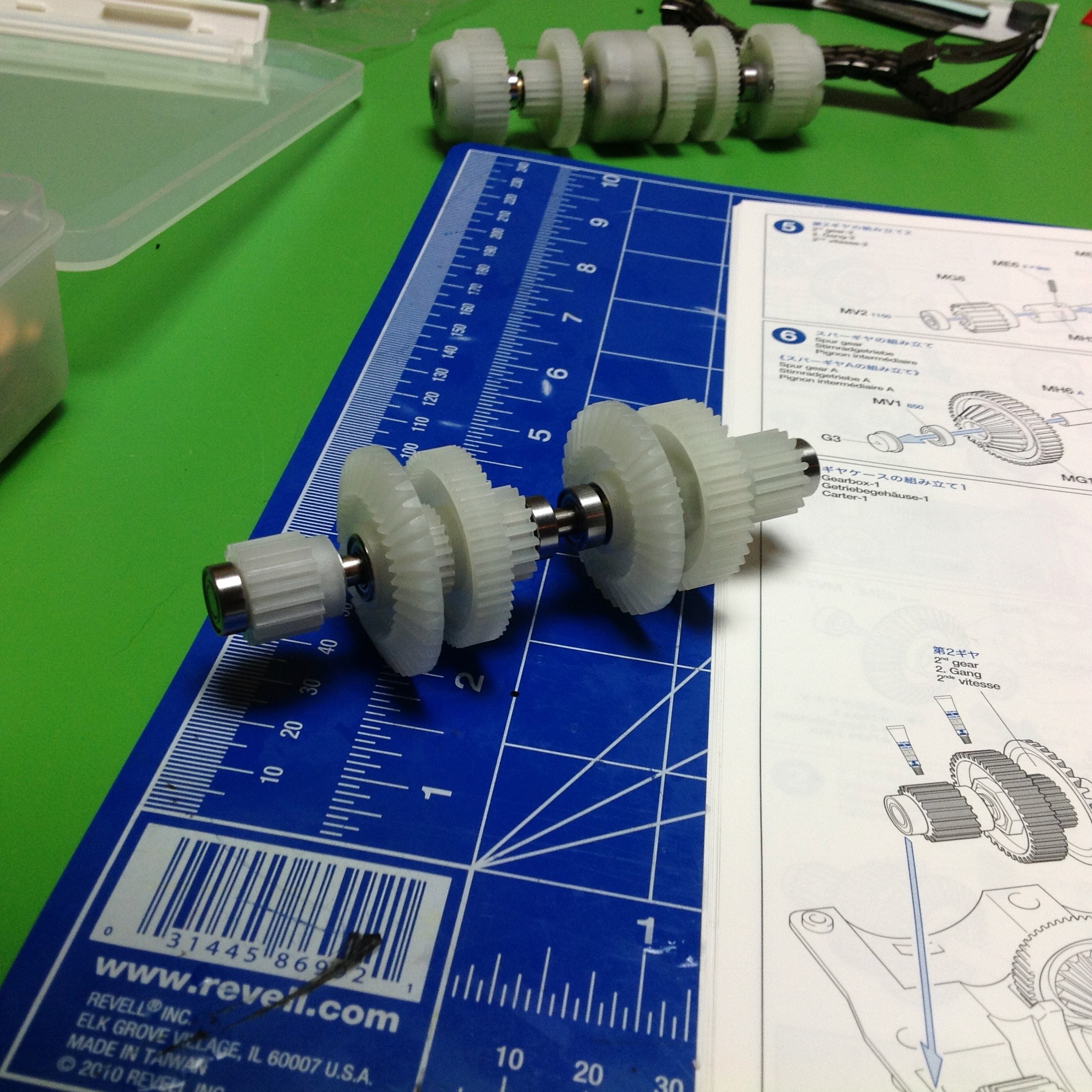
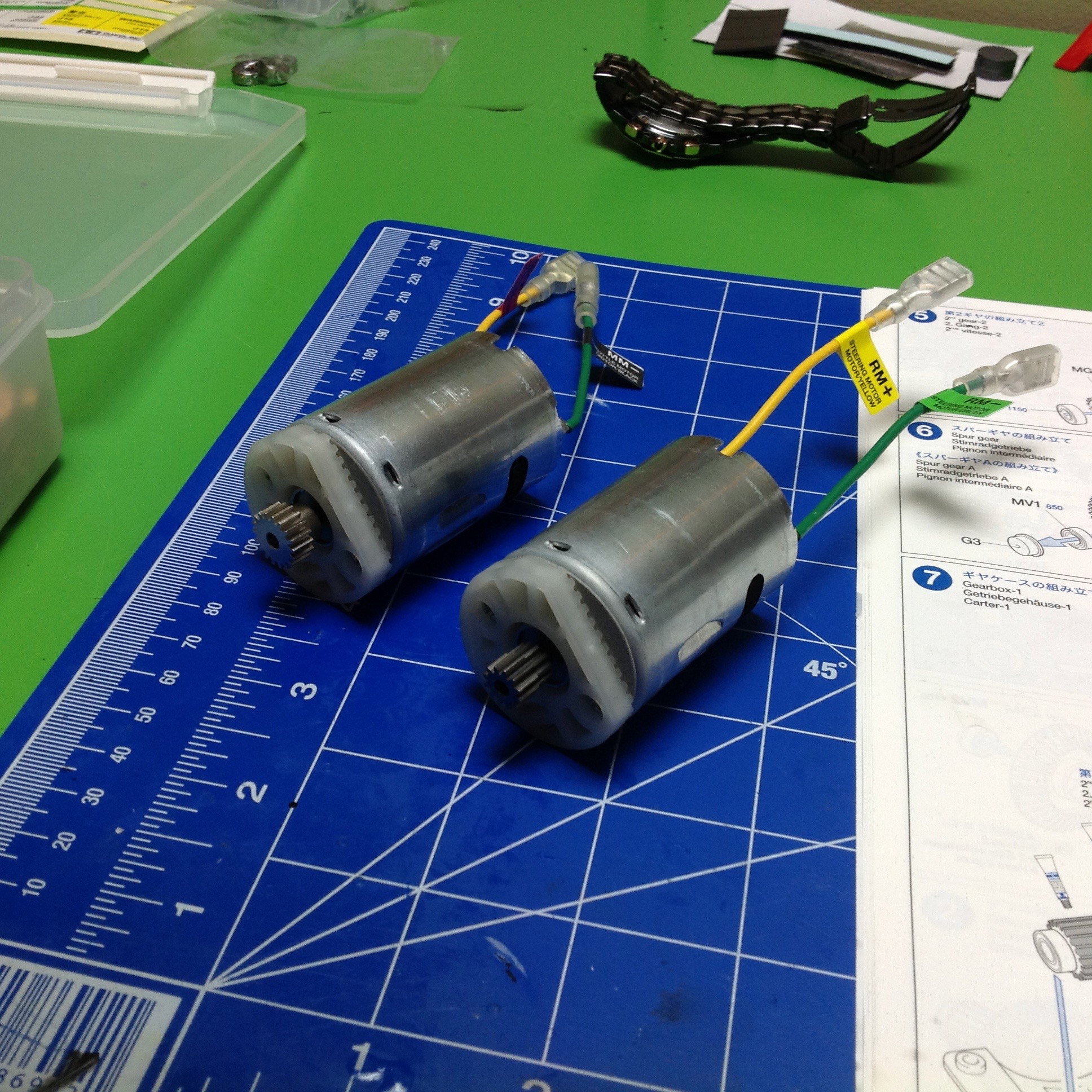
The second transmission shaft is even harder to explain, and it takes
two steps (4-5) to build it. This is one continuous shaft rotating
at one speed. From left to right (right hand image): 1st pinion gear is locked to
axle, 2nd bevel gear is free, 3rd spur gear is free, 4th bevel gear is
free, 5th spur gear is locked, and 6th pinion is locked. The
pinions at either end control output to the track sprockets through the
left and right differentials, so it is really that 5th spur gear that
drives them.
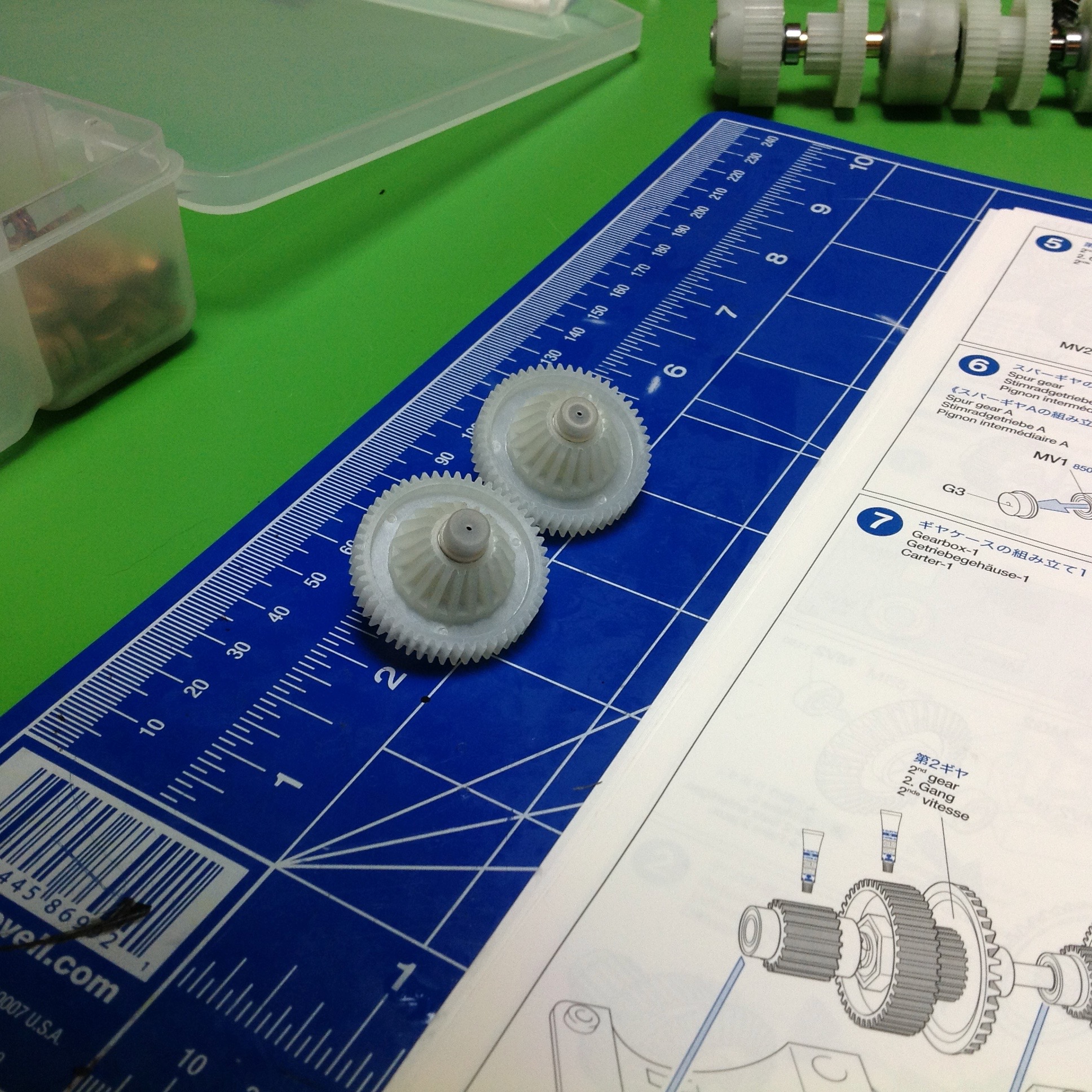
Step 6 builds a pair of bevel and spur gears which freely spin on axles. These will be the inputs from the motors.
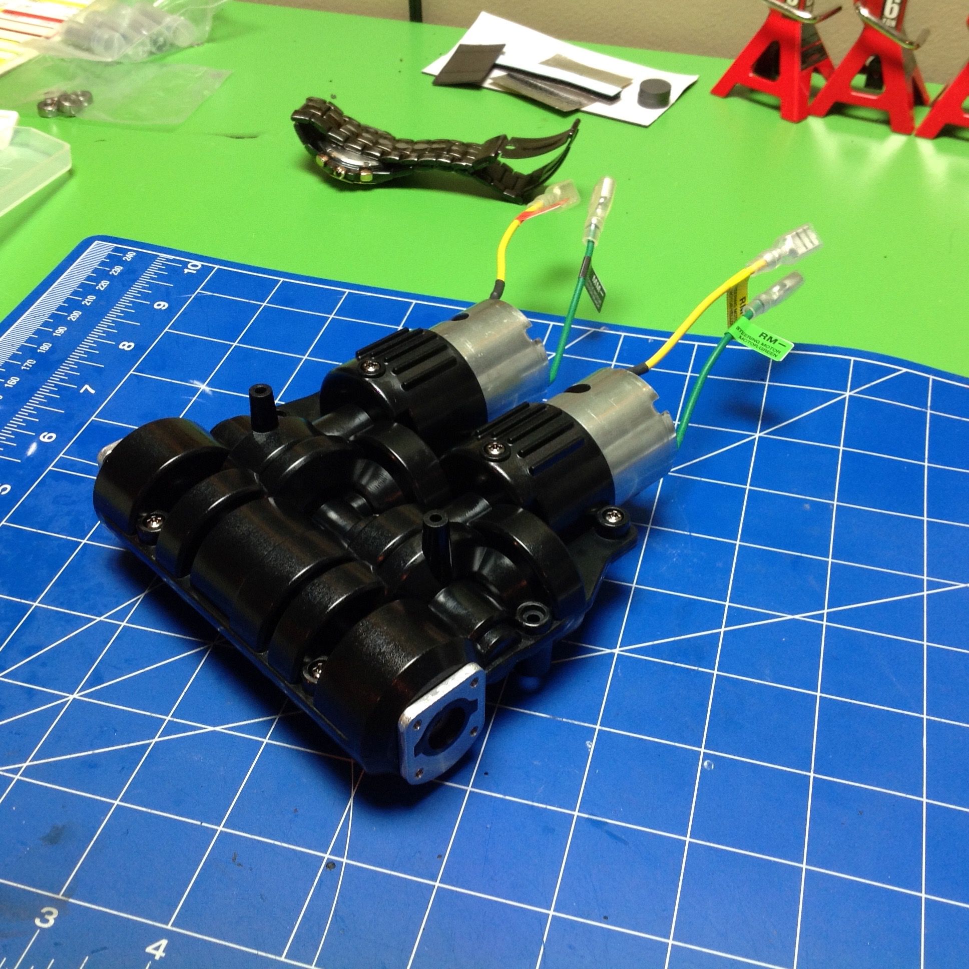
Step 7 finally shows how this whole thing goes together, and it is
cool. In theory it is very easy to power a skid steer
vehicle. You just connect one motor to each side and then control
them independently. In practice, the problem is that this makes it
almost impossible to drive straight because the motors are never
operating at exactly the same speed. Enter the dual differential
drive. In this setup, one motor is used for propulsion and drives
both sprockets equally. The other motor is used for steering and
drives the sprockets in opposite directions. These systems are
summed with differentials such that combination of the two is possible in
any proportion. This nicely solves the problem of going straight,
but also means that you need twice as much power in your drive motor
because you are only using one. That's why this tank uses 540 sized motors while many of the others use 380 motors.
The motors' inputs at the top of the image drive the large spur
gears. The bevel gears make the 90 degree corner and pass through
two idler stages before coming back to the small pinions. It is
convenient to use the same axles for the idles gears because it saves
space. The left hand input is the drive motor. After the two
idler stages, it drives the large spur gear on Axle 2 which is locked
to the pinions. These pinions drive the ring gears of the outer
diffs, thus turning both sprockets in the same direction. The
right hand steering motor has almost the same path except that the spur
gear is not locked to Axle 2, instead it uses another spur gear locked
to the right side of Axle 1. This forces the left side to rotate
the opposite direction. Note that steering also has more
reduction than drive which is useful because steering takes a lot
more power to skid the tracks.
Note that this drive system is fundamentally different than most of the
other 1/16 tanks which use dual 370 motors each driving independent
gearboxes, left and right. In that case, the power levels of each
motor are modulated by the DMD control unit so that the driver input is
like traditional throttle and steering. This tank is different in
that the DMD does no mixing at all, it just converts the radio signals
directly into power levels for the drive and steering motors. All
the mixing is done mechanically. This allows literally any
proportional combination of drive and steering.
Update: Reading this back years later, I can see how
difficult it is to understand the transmission without some further
explanation and visualization. I'll try to do better. Let's
use some torque diagrams to show what's happening. The key to
understanding is knowing that some gears can rotate freely on their
axles while others are locked to their axles' rotation. There is
no way to know just by looking at a photo, you have to study the
instructions. I'm going to go through the painful process of
counting teeth off the instruction pictures to figure out the gear
ratios here.
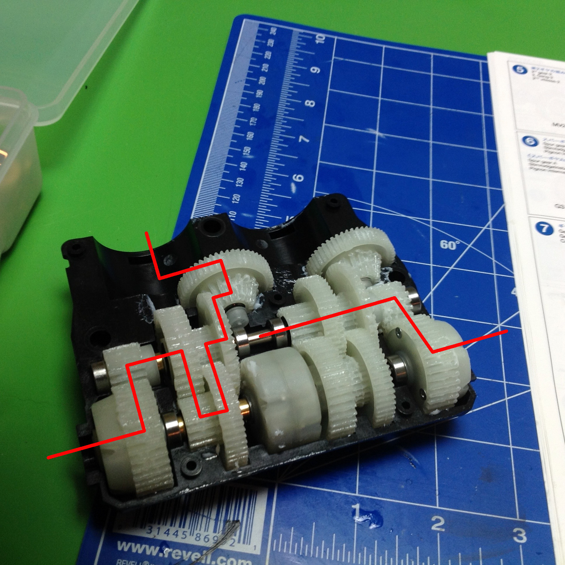
The first picture shows the drive system torque path in red.
Staring with the motor (which isn't installed yet), we have a pinion and
spur with 18:52. The second stage bevel gear pair is 18:36.
This gear is NOT locked to Axle 2. The third stage spur gear pair
is 24:52. This gear is NOT locked to Axle 1. The fourth
stage spur gear pair is 18:39. This gear IS locked to Axle 2 so
this axle is now locked to the drive motor which powers the final
pinions on both ends. The output to the differential (fifth stage)
is 18:39. Note that because we are driving a differential spur
gear but one side is locked (by connection to the steering motor), we
get an additional 2:1 ratio on the output. If my math is right,
the final drive ratio from the motor to the sprocket is 29.4:1.
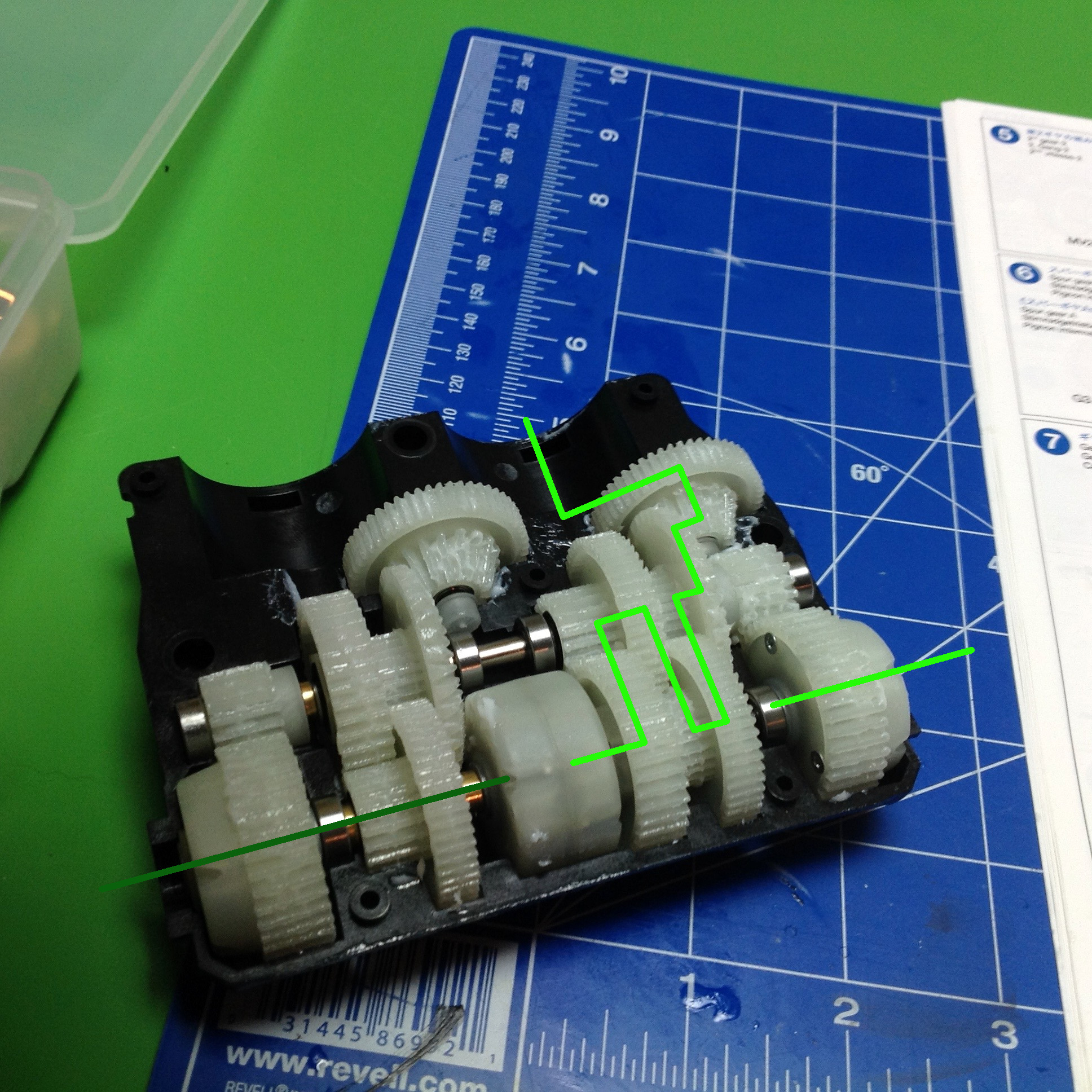
The second picture shows the steering system torque path in green.
Starting with the motor (which isn't installed yet), we have a pinion
and spur
with 12:52 (a smaller pinion than that used by the drive motor). The second stage bevel gear pair is 18:36. This
gear is NOT locked to Axle 2. The third stage spur gear pair is
24:52. This gear is NOT locked to Axle 1. The fourth stage
spur gear pair is 24:52. This gear is NOT locked to Axle 2.
The final stage spur gear pair is 18:39. This gear IS locked to
Axle 1 so this axle is now locked to the steering motor which powers the
output differentials through the center differential which forces them
to rotate in opposite directions. If my math is right, the final
steering ratio from the motor to the sprocket is 88.2:1.
After everything, there is exactly a 3x difference between the drive
ratio and the steering ratio, and all of that comes down to a different
pinion (1.5:1) and the 2:1 in the output drive differential.
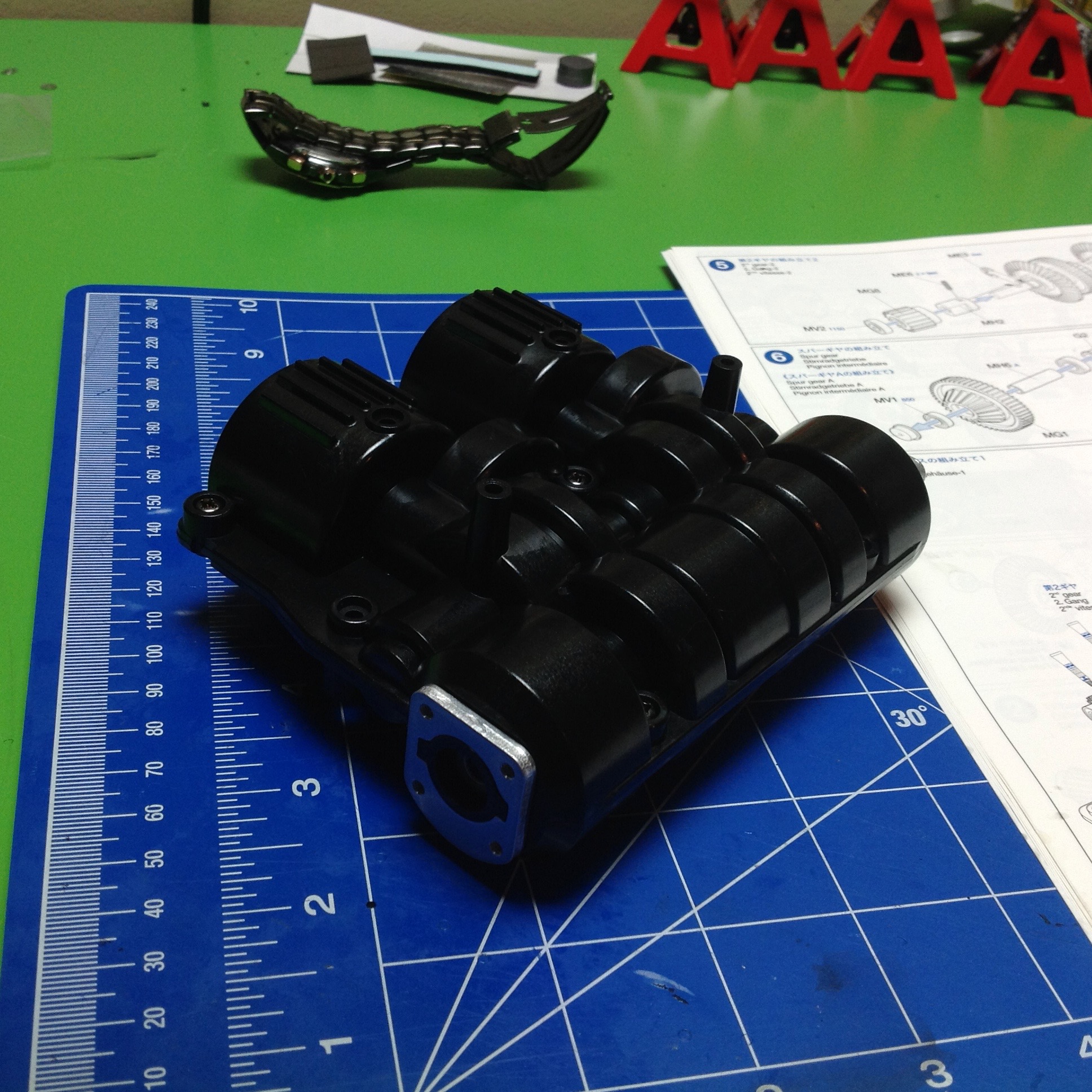
Step 8 puts the cover on the transmission and hides all that lovely rotating goodness. Now it's just a magic box.
Step 9 prepares the two motors by applying a gasket, an anti- rotation
block, and a pinion to each motor. The motors are the same, but
the pinions have a different number of teeth. The steering motor
is geared lower.
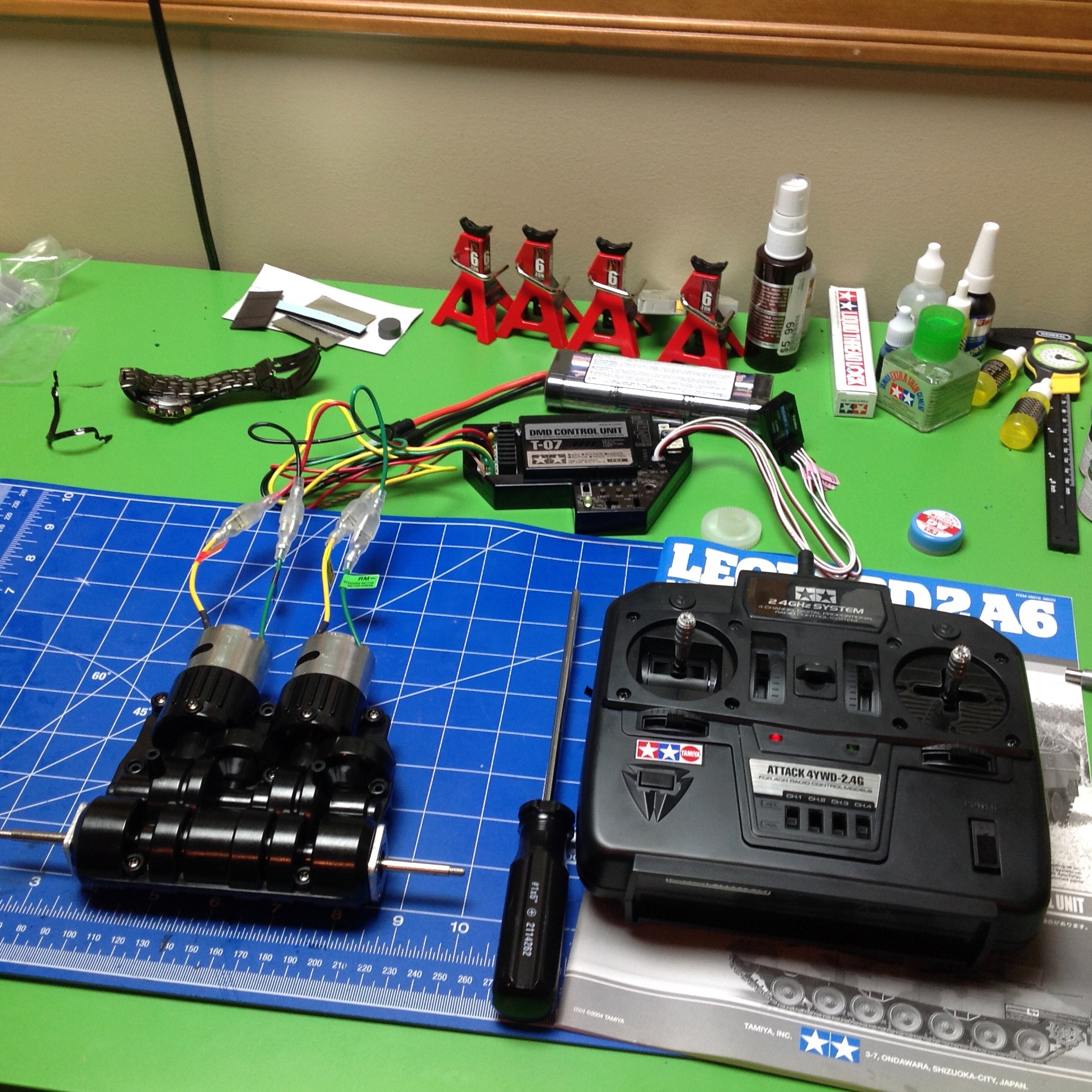
Step 10 attaches the motors to the gearbox housing, completing the
transmission. At this point nothing is stopping us from hooking up
the control system and trying it out, which of course is exactly what I
did. I connected the motors to the control unit, and the control
unit to a receiver and a battery. It is very easy to see the
mixing of steering and drive happening by watching the output
axles. I also removed the housing top cover so I could see the
gears in action and better understand the function of the
transmission. Given the huge face width on all of the gears, it is
quite likely I will never need to open this for maintenance
again. That's a good thing because it turns out that accessing the
lower hull once the model is completed will be very difficult.
©2017 Eric Albrecht