MAN TGX Project
Page 2: Crane Assembly
I'd never built anything quite like this crane before and was not sure
what to expect. Part of my trepidation was due to the fact that
this is a real hydraulic model, and part was lack of familiarity with
the brand. You just never know what to expect from an unknown
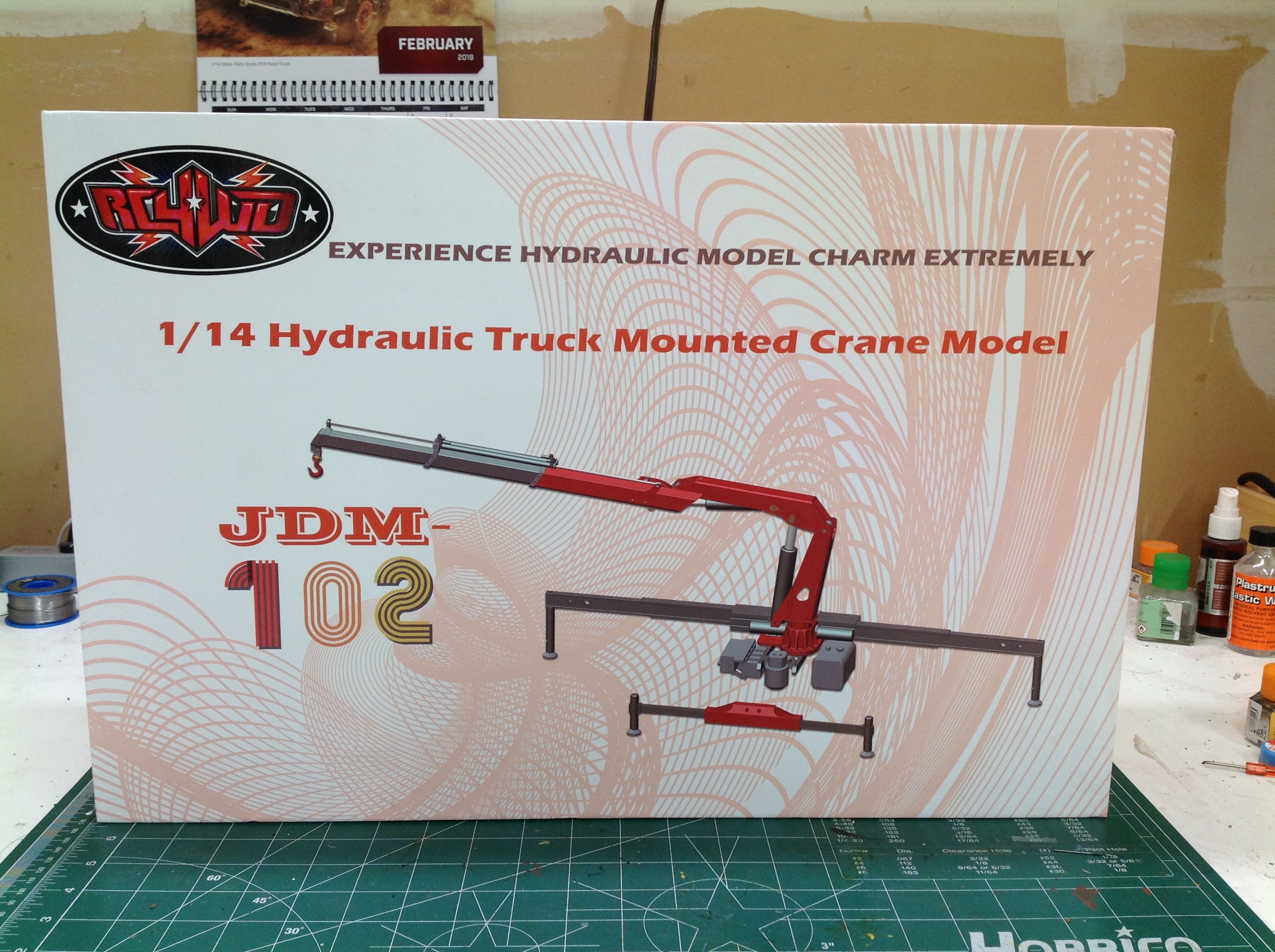
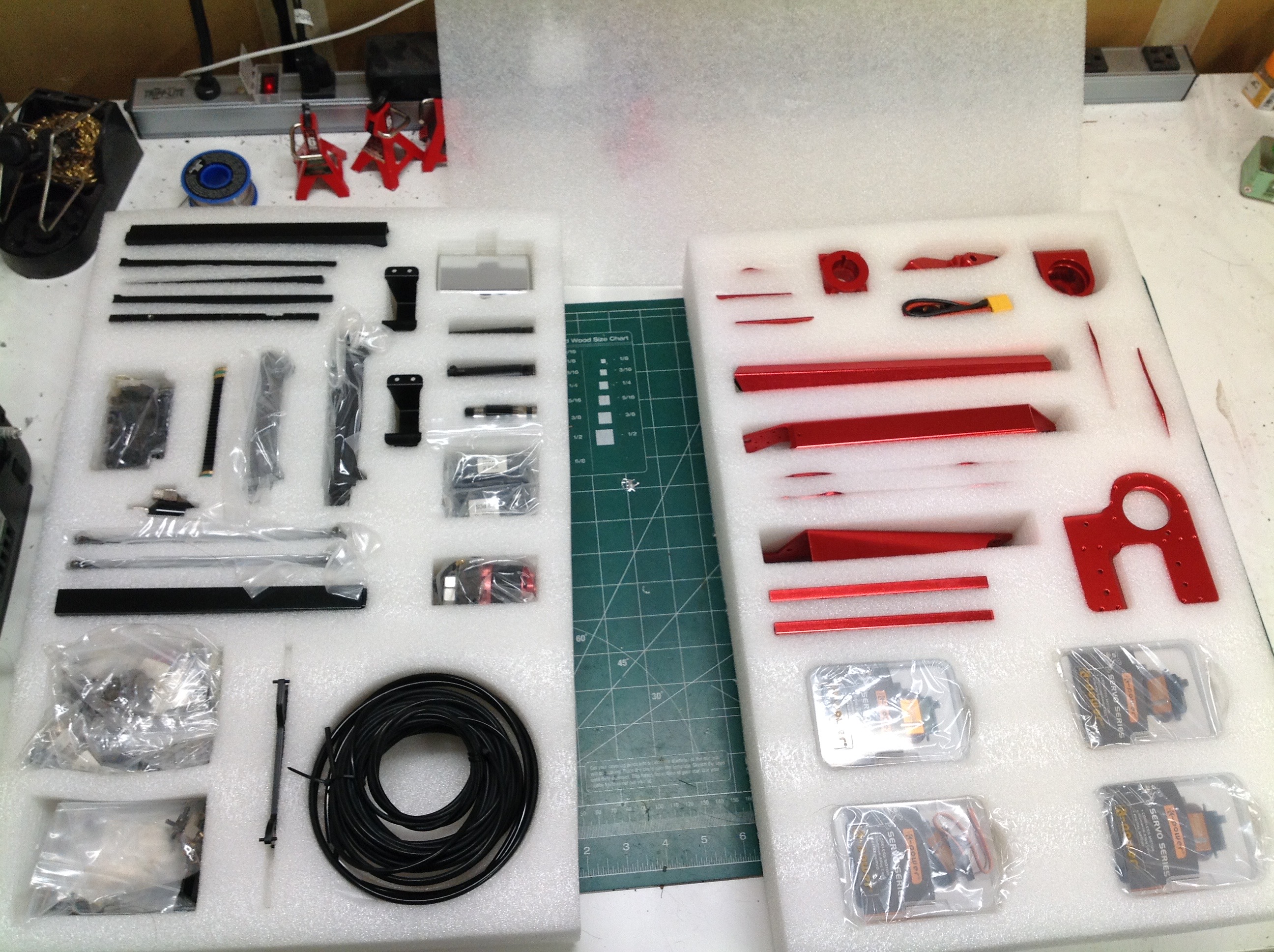
Chinese brand. Luckily for me, the packaging did a lot to assuage
my fears. The kit comes in a very thick box with everything
individually packed in foam dividers. Every single part of this is
metal: aluminum, steel, or brass.
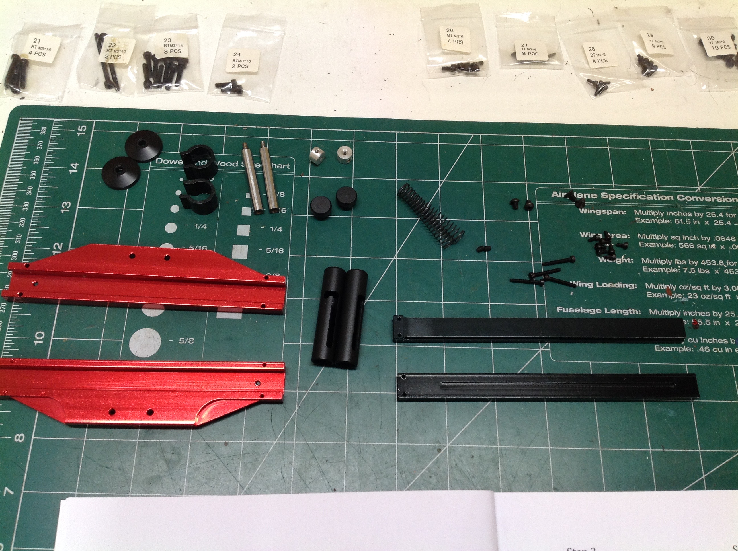
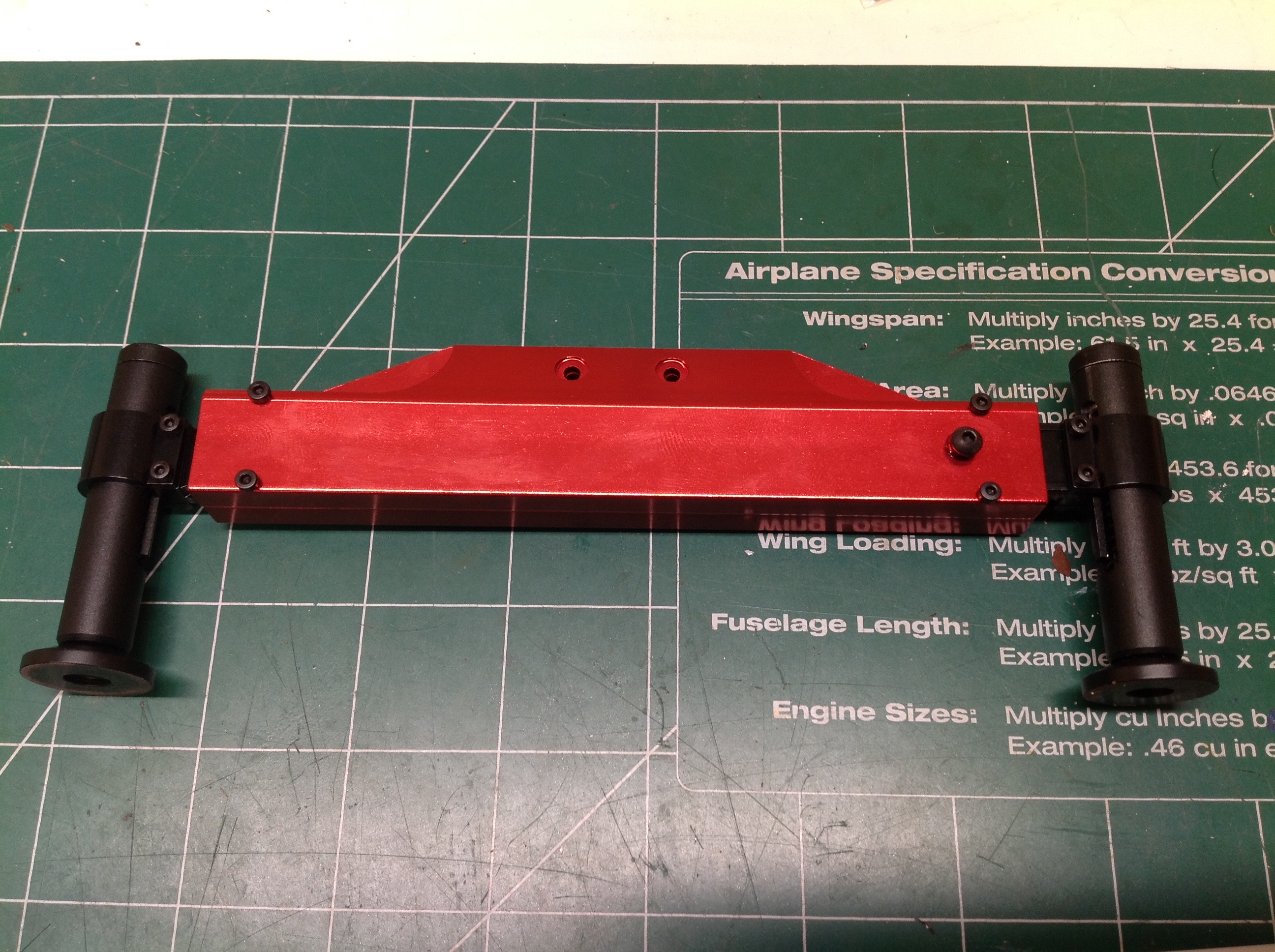
We'll start with the easy parts: the outriggers. The outriggers on
this model are not hydraulically powered. Instead they are
manually extended and lowered. Each foot locks into the extended
position which makes it possible to support the whole truck. The
unit shown is for the rear outriggers which go behind the back
bumper. The two extendable arms overlap each other when
retracted. There are set screws which poke into a groove in the
arms to keep the arms from over extending and falling out, but one of
the predrilled holes did not line up with the groove so the screw could
not be installed. Score -1 for quality on the first step.
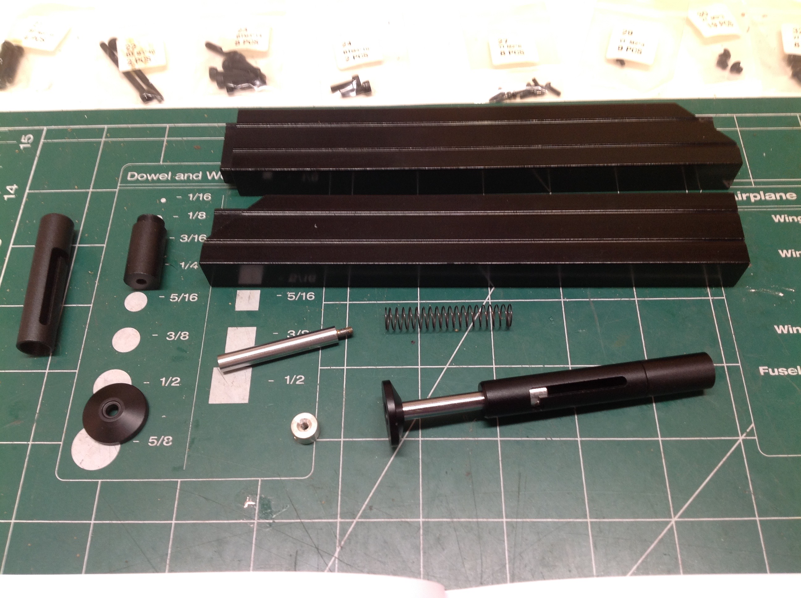
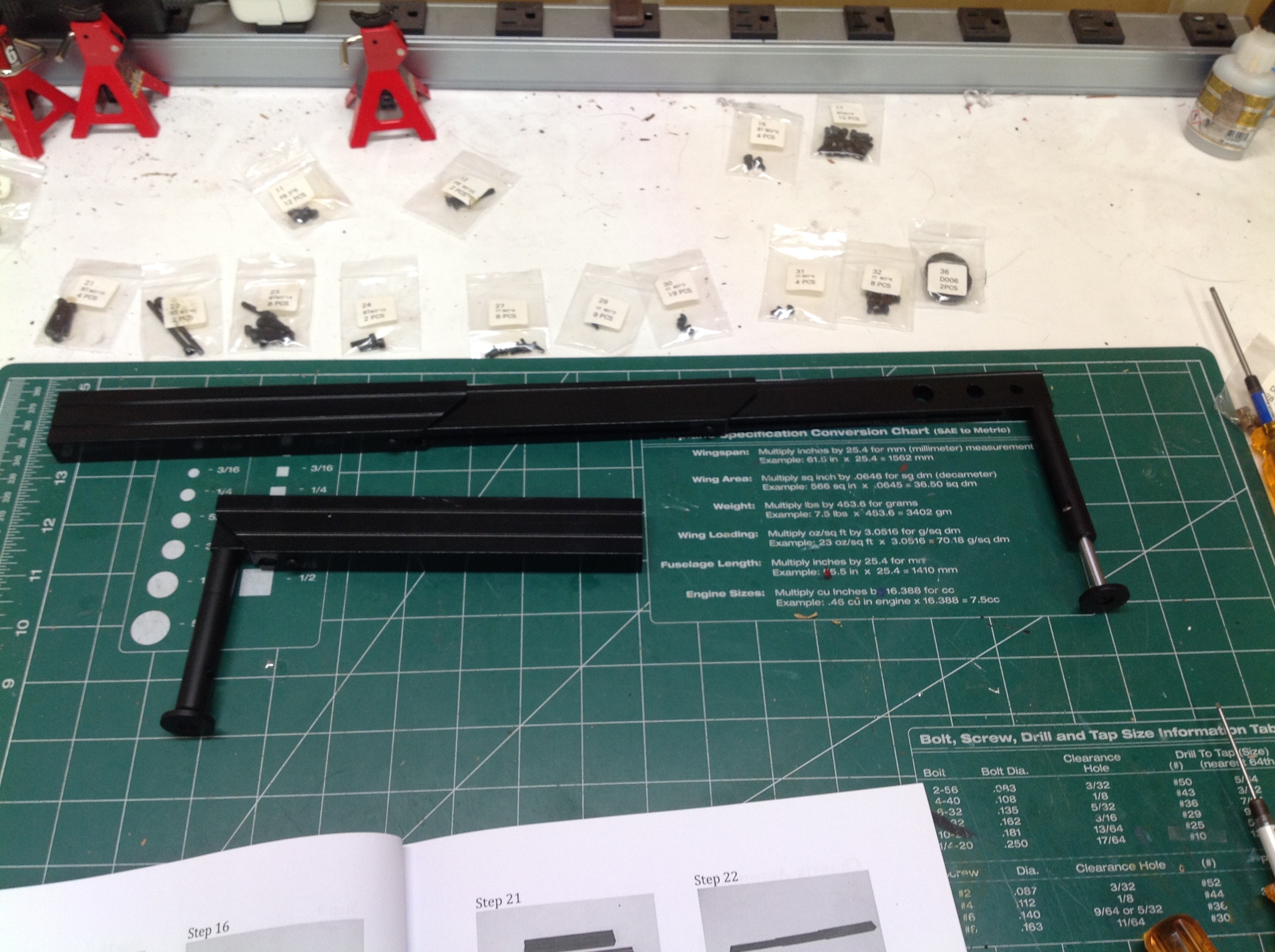
The front outriggers which sit right behind the truck cab are completely
different. These are 3 stage telescoping units which are very
long indeed. Because the arms must sit above the chassis rails,
the cylinders for the feet are much longer than those in the rear.
The spring that you see on the left is used to hold the foot in the
retracted position when driving. The telescoping arms have no such
spring though, so they tend to fly out when the truck is
cornering. I added some black electrical tape to make them fit
more tightly and stay in place.
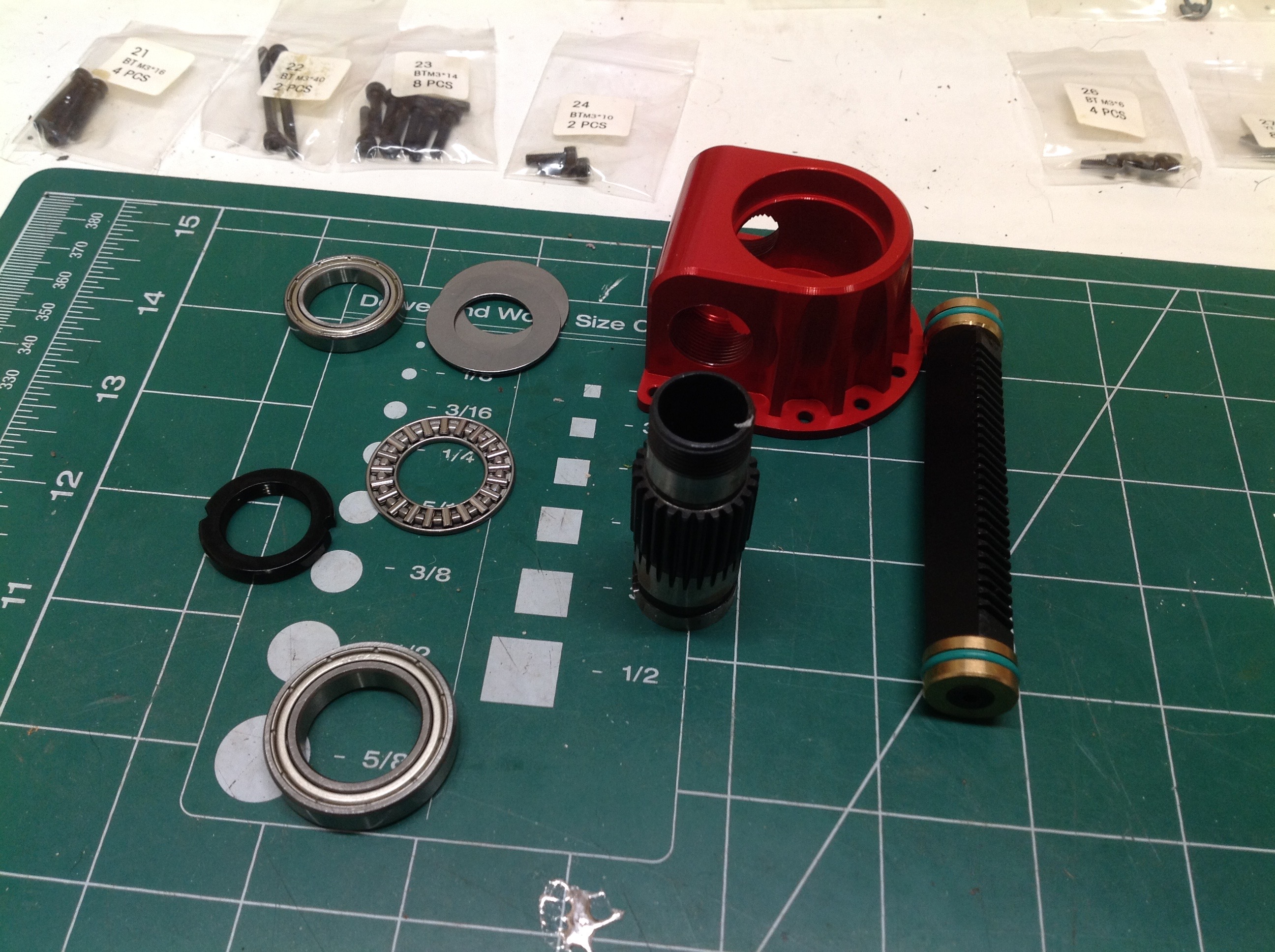
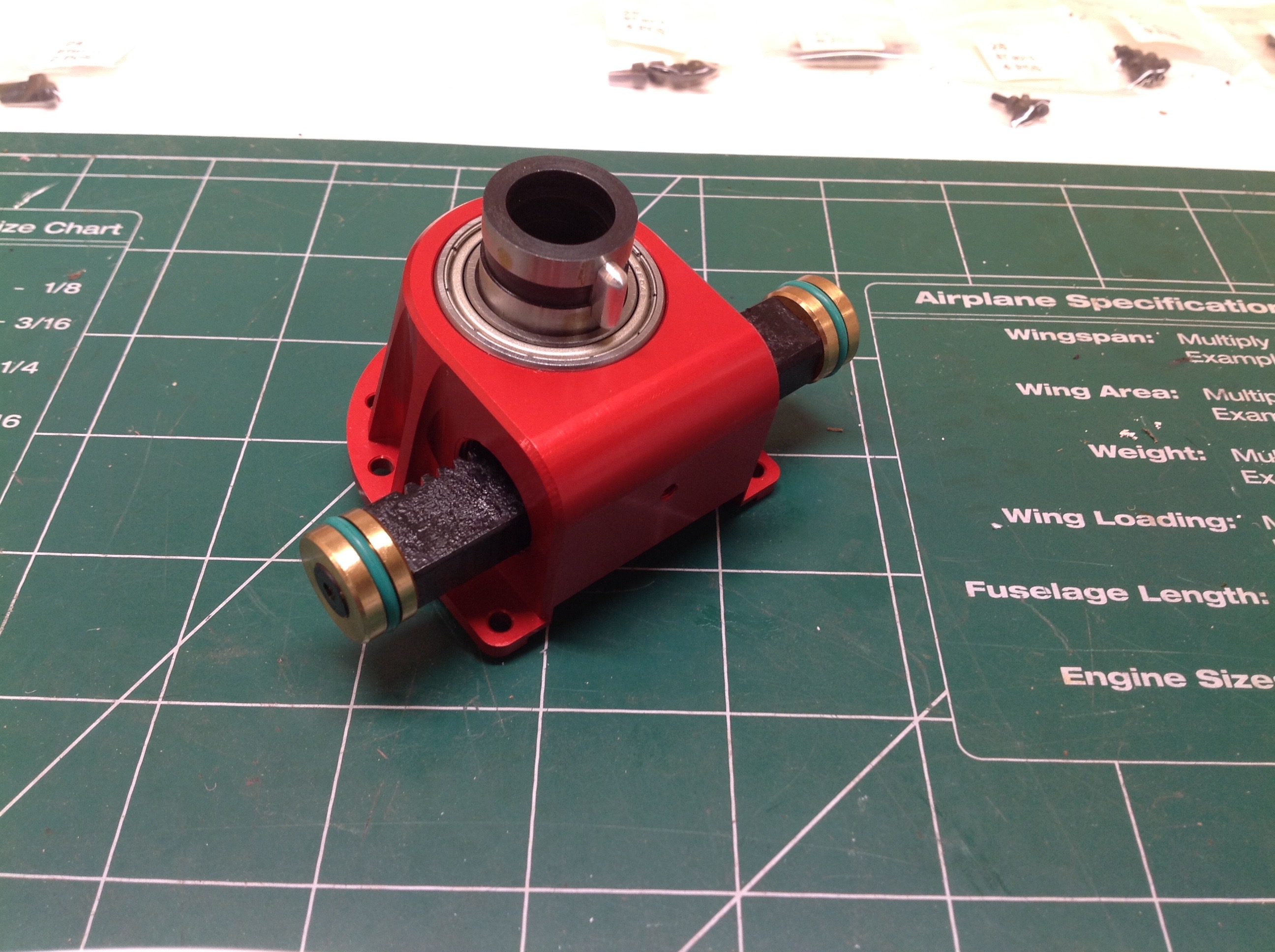
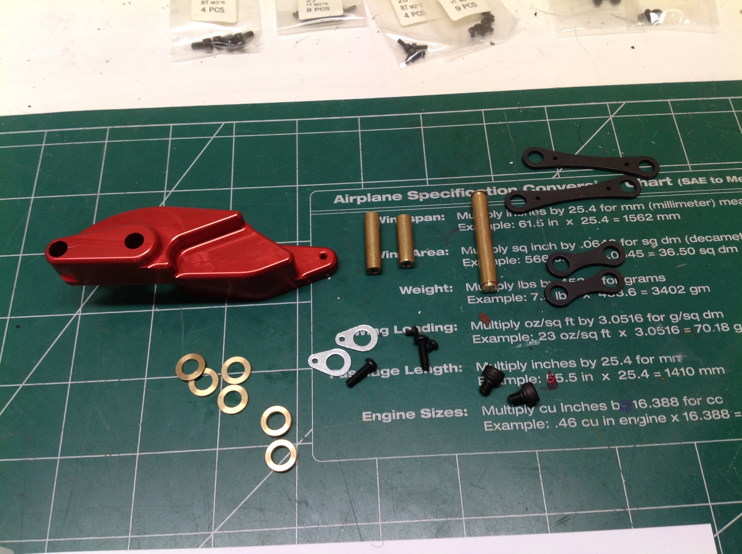
Now we'll start working on the actual mechanical bits. Shown on
the left are the parts for the turntable. The vertical shaft
serves as a pinion gear and the horizontal shaft is a rack. You'll
notice that the rack has o-rings at each end because it also serves as a
piston for the slewing cylinders. The slewing cylinders are
single acting (they only push) so only one side is pushing at a time to
slew the boom. There is also a thrust bearing using cylindrical
rollers to support the weight of the crane arm without adding too much
friction to the mechanism. All of the hydraulic lines for the boom
cylinders must pass through the center of the pinion gear.
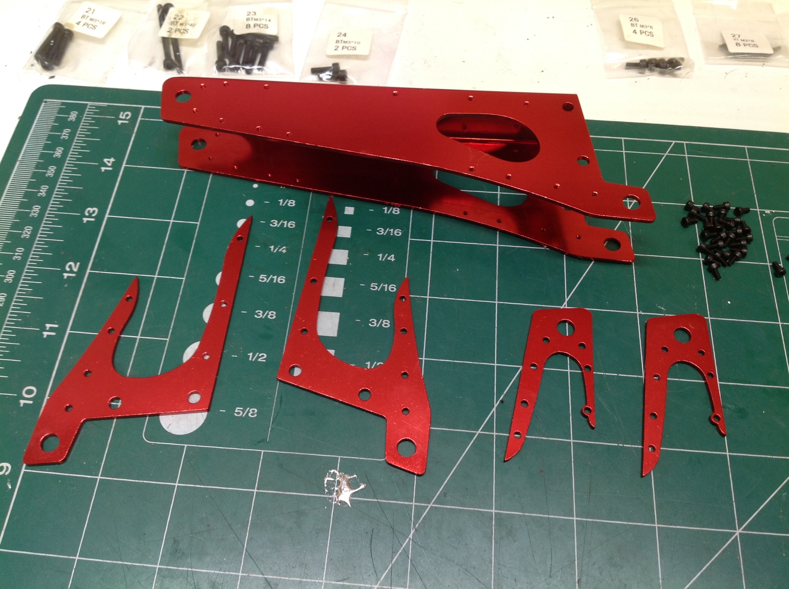
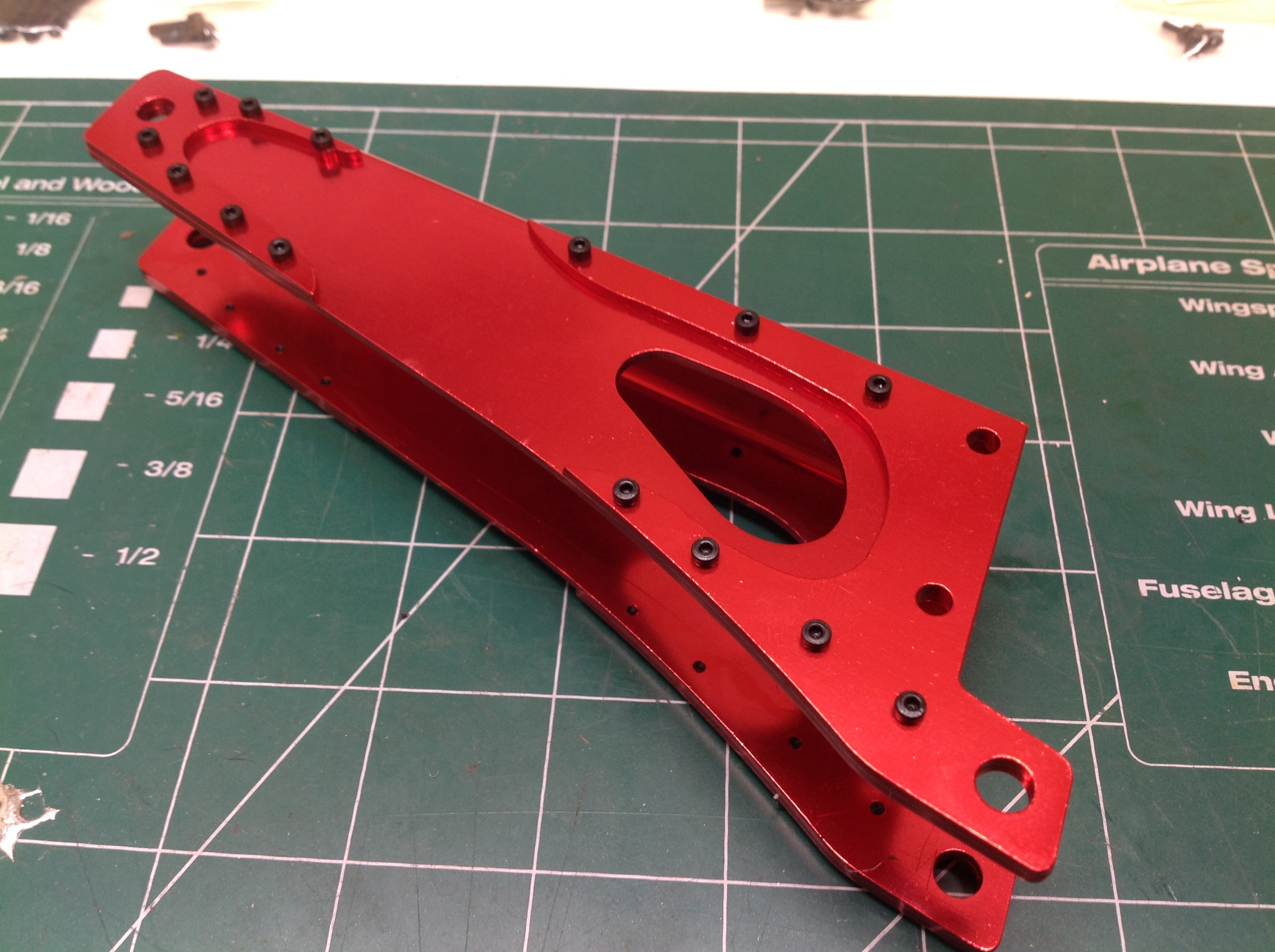
Shown on the left are the parts for the lower boom arm. The main
structure is a sheet of thick aluminum bent into a C-channel. A
series of 4 stiffeners are bolted to the side. Not all of the
holes lined up properly so it was a challenge to install some of the
tiny cap screws. The openings on the sides of the arm are not
strictly necessary, but they do provide some visibility of the tubes
that will be routed here later.
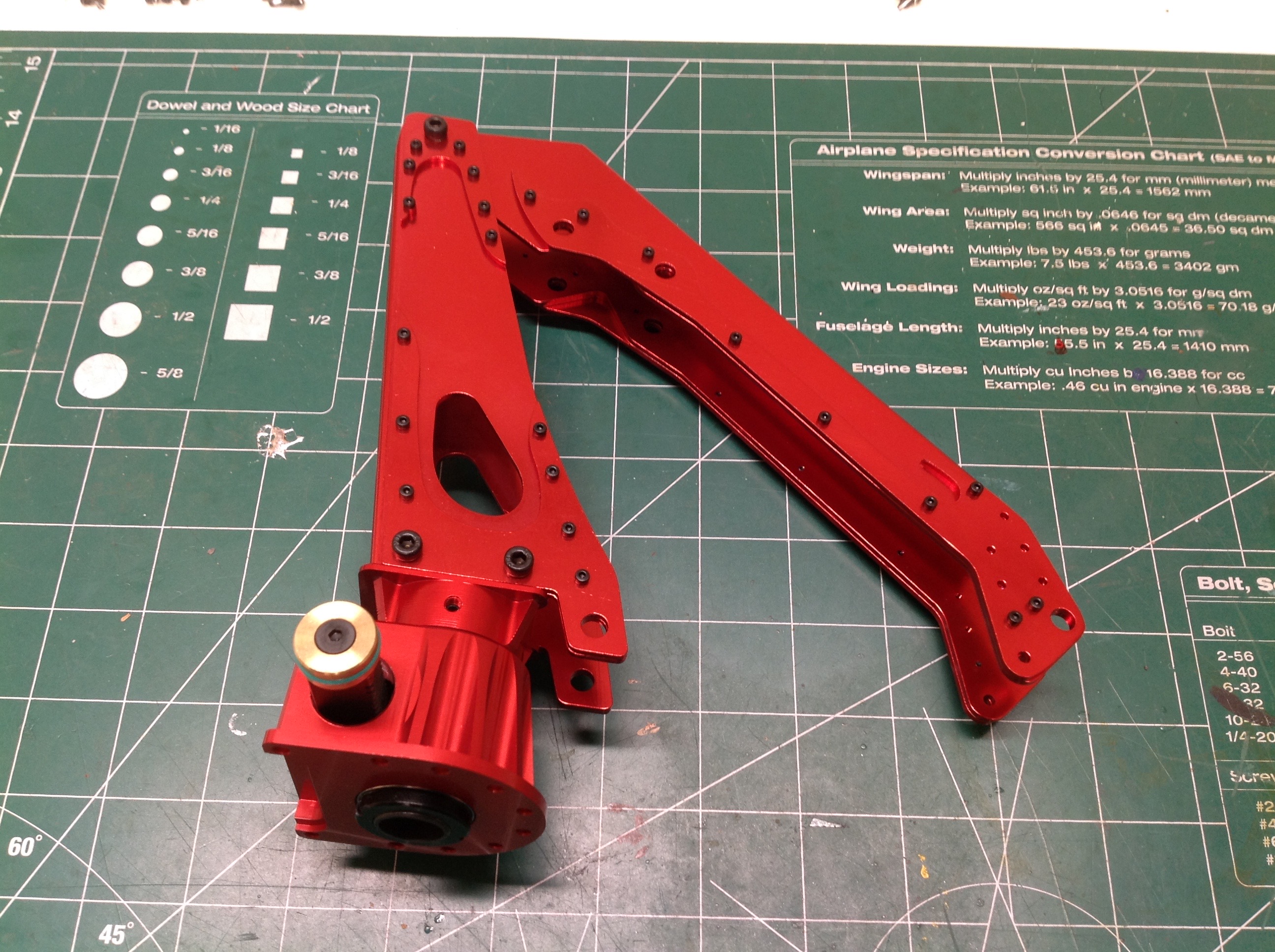
Here the lower arm has been attached to the turntable with 4 screws. This arm only rotates, it does not pivot.
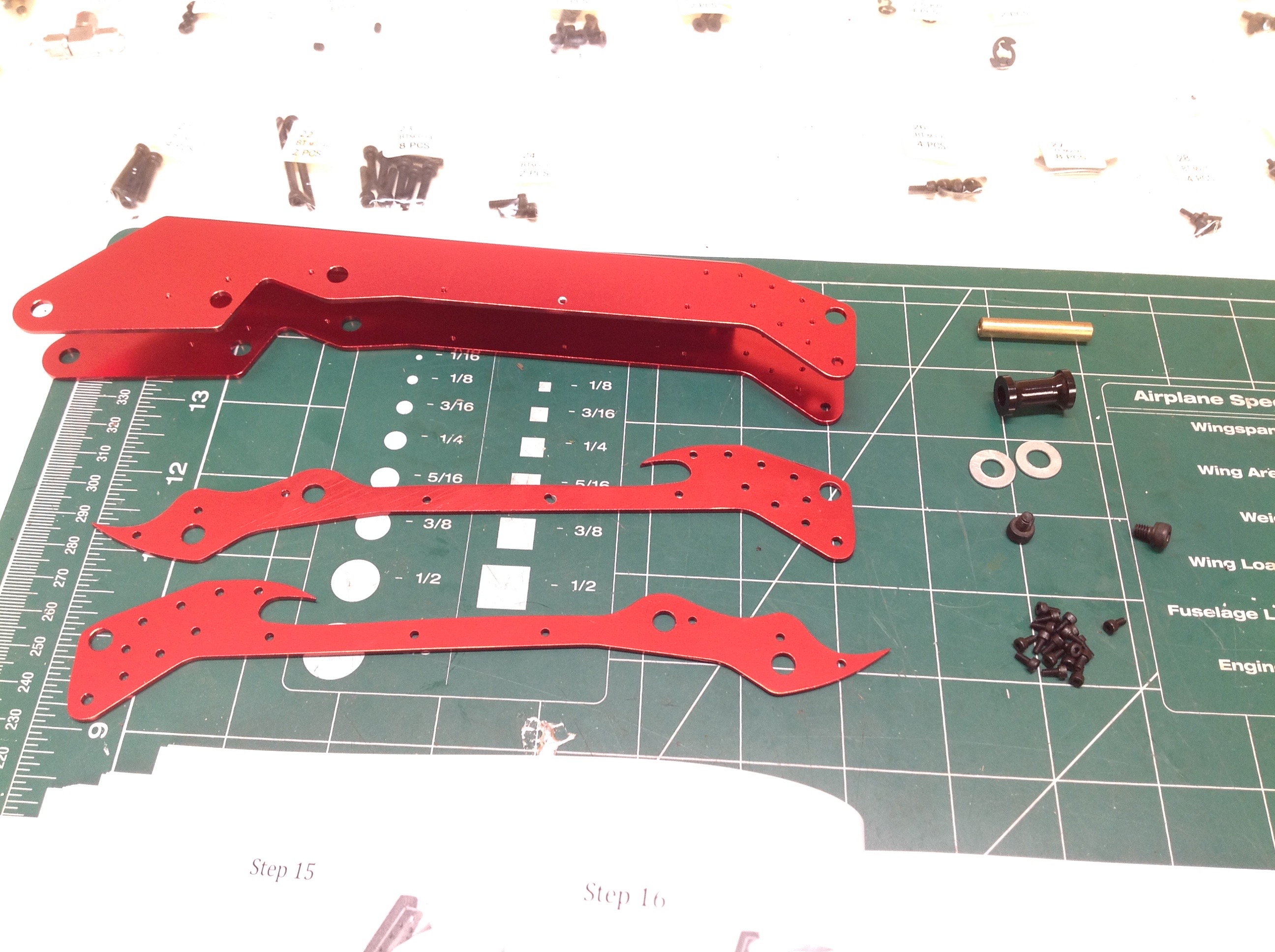
On the left are the parts for the main moving boom. Again we have a
C-channel main structure and bolted stiffeners. The brass pin
serves as the pivot axis. The second arm has been attached to the
first on the right. It's starting to get heavy.
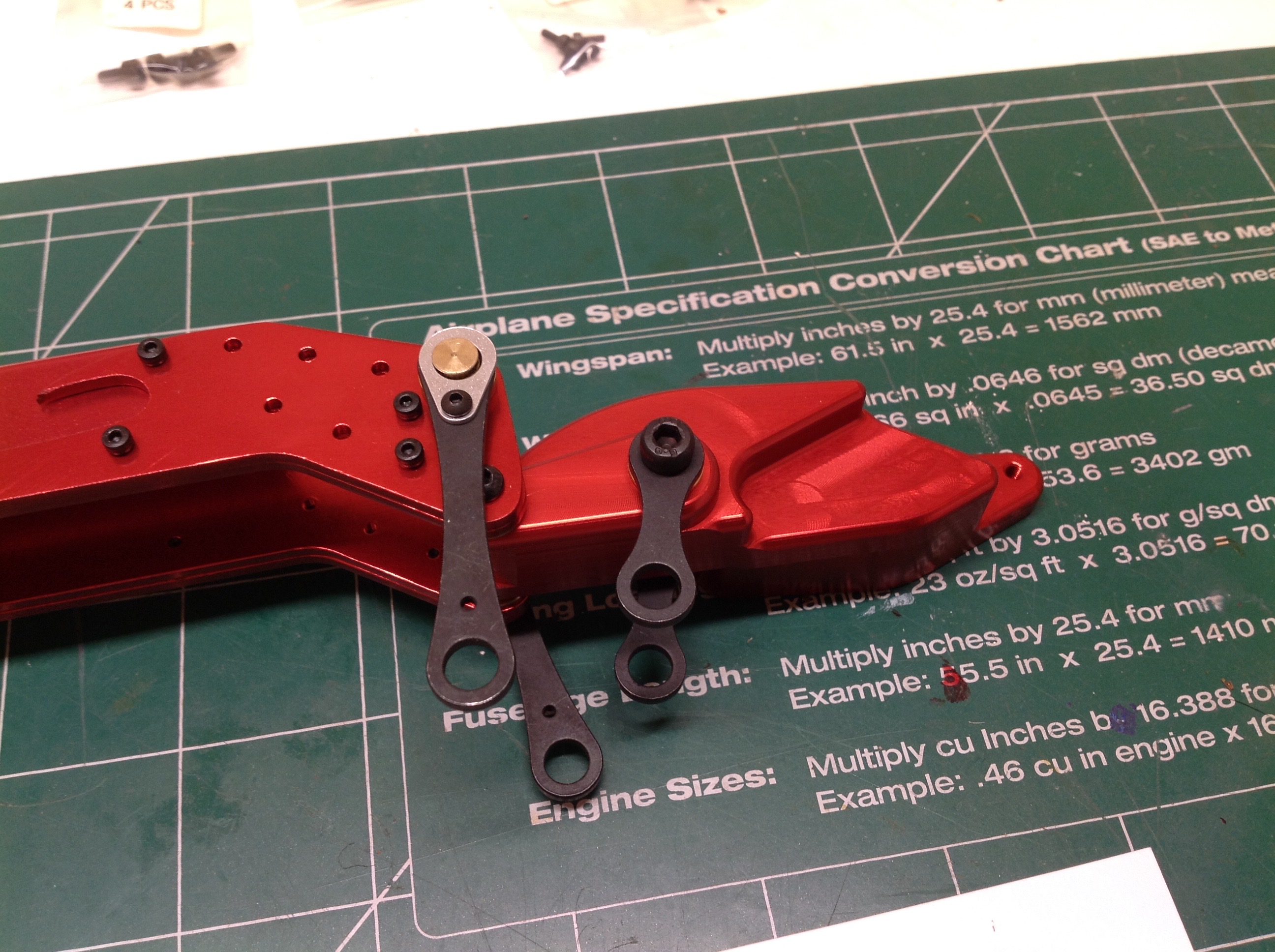
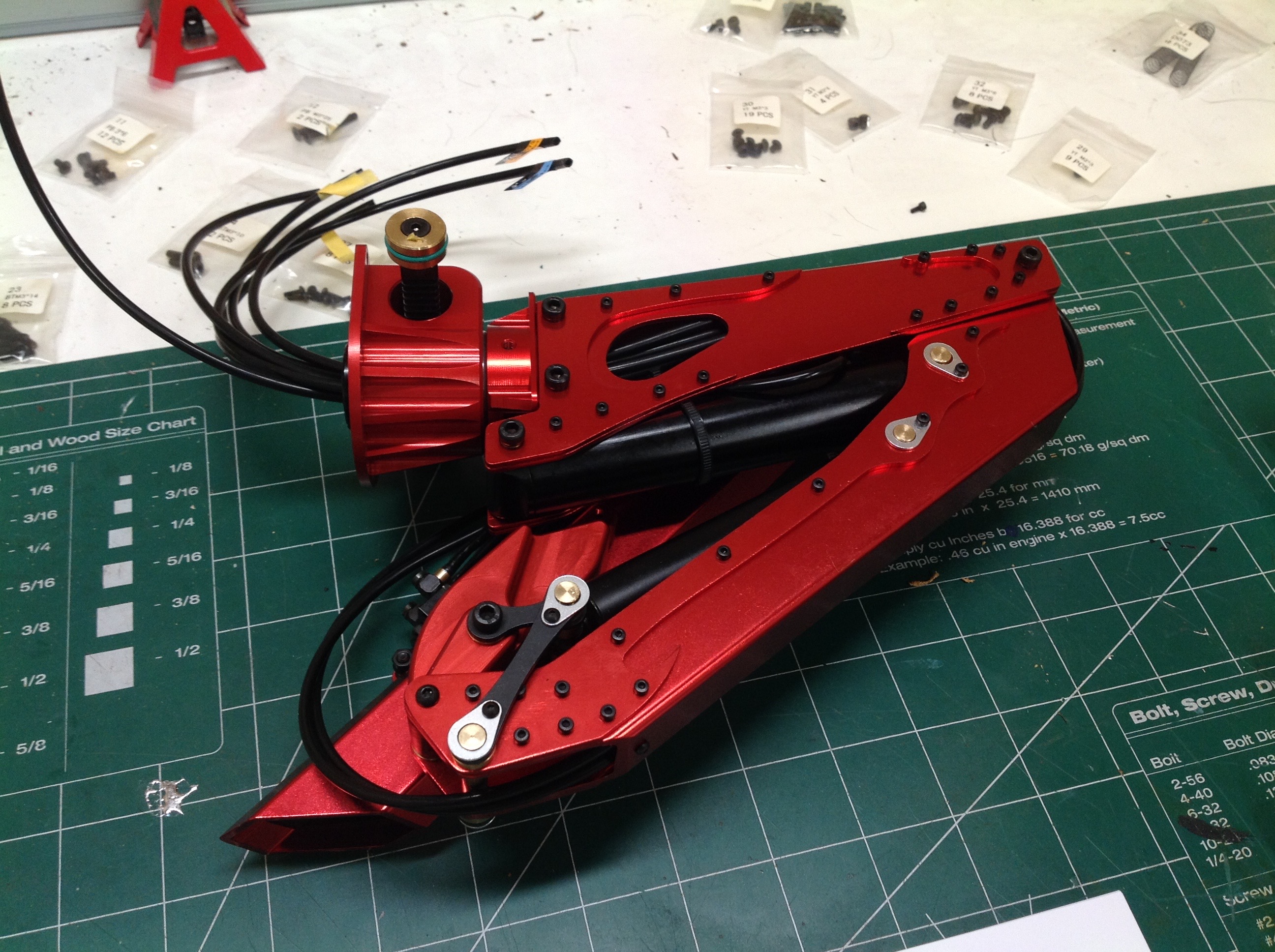
The third arm is sometimes called the knuckle boom because it folds
somewhat like a finger. In order for this arm to overlap the
others it must be offset to the side. Putting one arm in a
different plane causes a lot of stress so this joint has to be
strong. The heavy machined aluminum fitting you see here serves
are the knuckle. The dogbone links will guide the lift cylinders.
The third arm is a closed box section with no obvious seams so I assume
it is extruded rather than formed. I slides over the end of the
knuckle and then bolts in place.
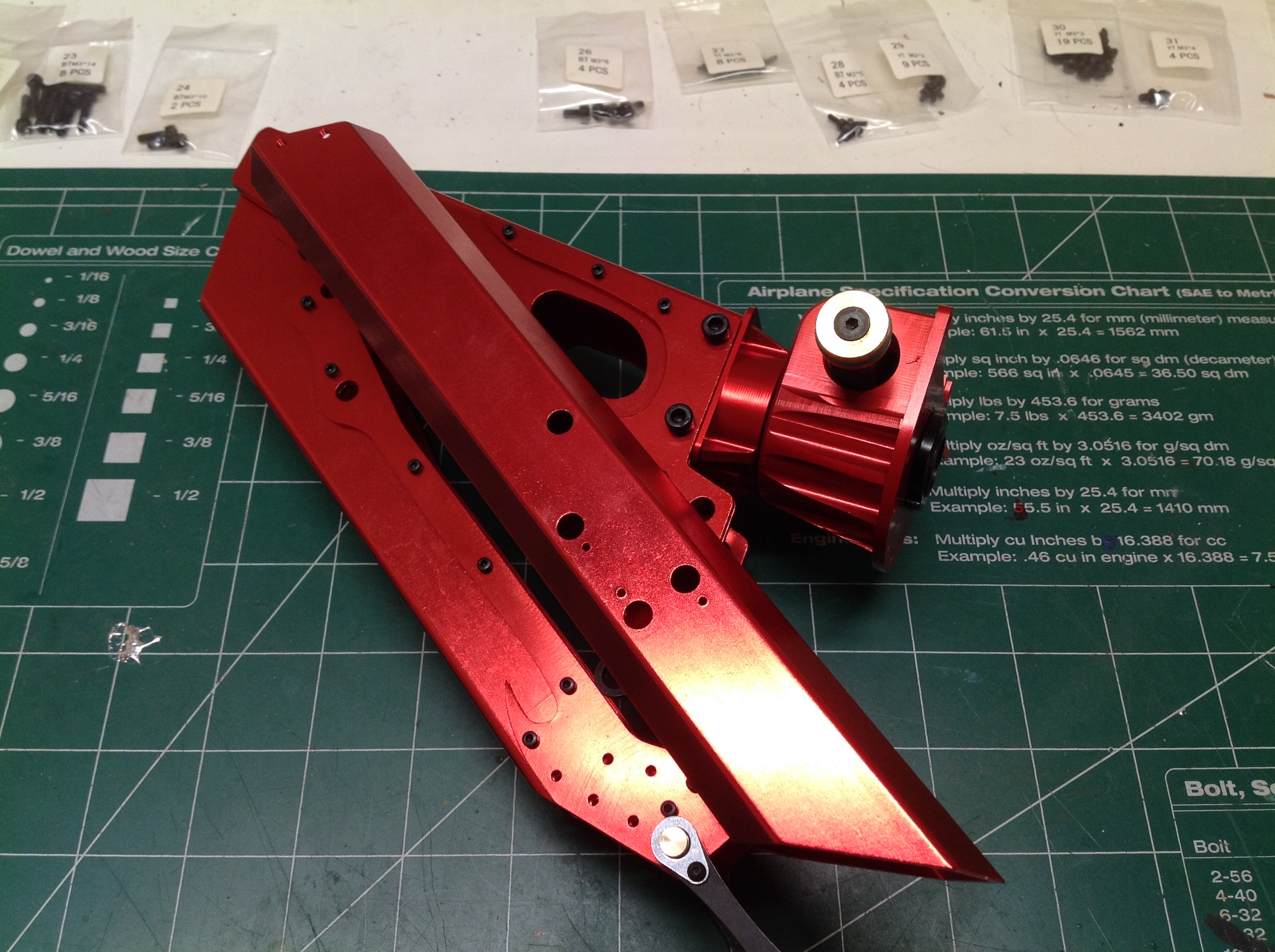
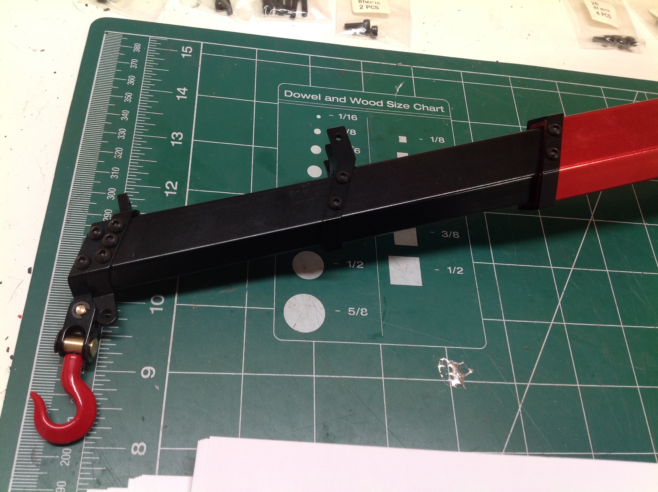
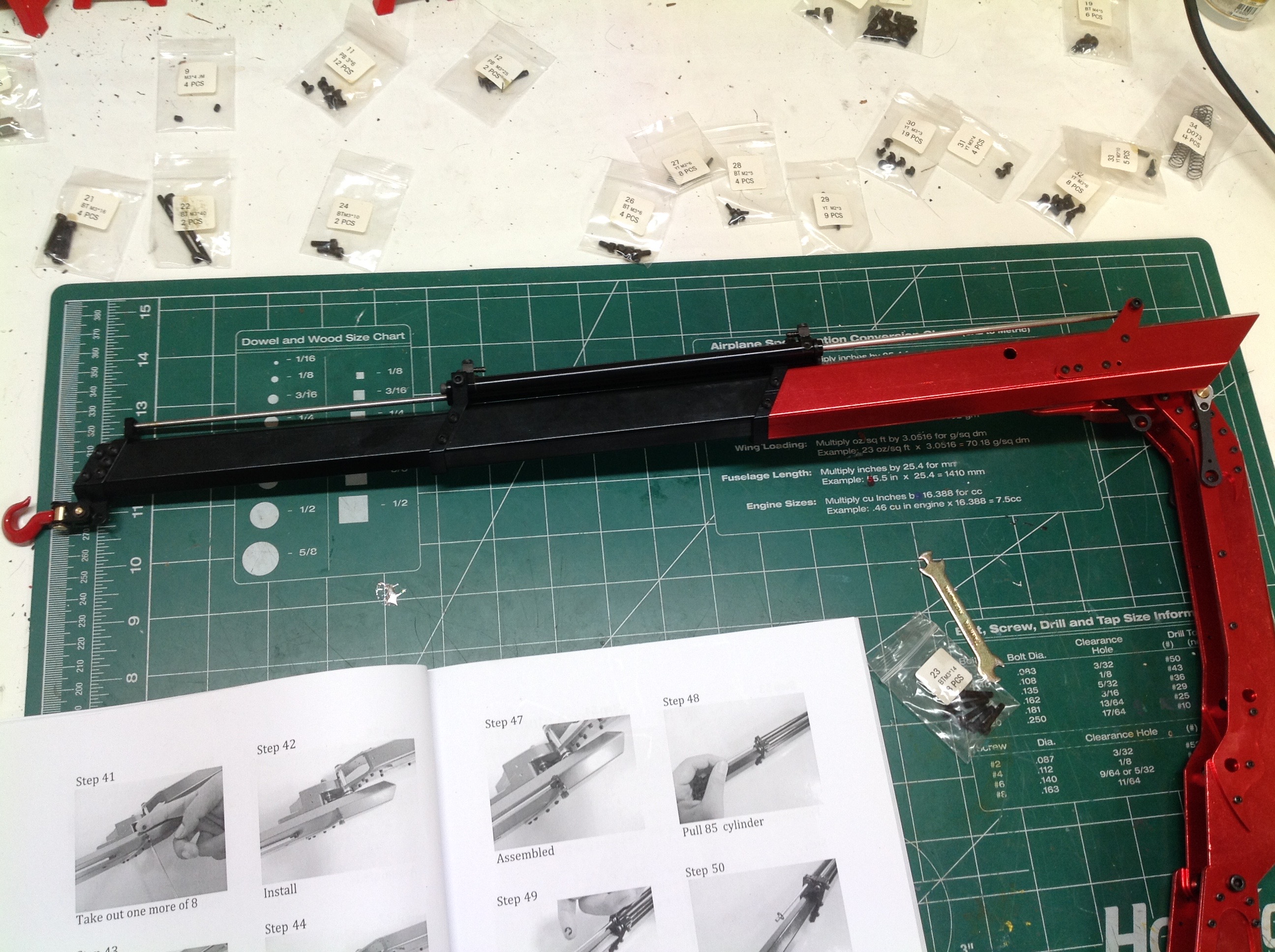
The final arm is a 4-stage telescoping boom, so that means three other
box channels must slide inside the first. The sliding channels are
all black. The first two stages are hydraulically extended by the
long thin rams shown on the right. They are plumbed together back
to back so they both extend or retract together. Their fixed ends
are mounted to the first moving boom stage which means the whole
cylinder moves outward as the boom extends. The third stage can
be extended manually (not pictured) by loosening a set screw. It
must be manually stowed again before the crane can be folded. This
last section is seldom used, but allows for extreme reach when
needed. The hook on the end is totally unpowered and can swivel on
two axes.
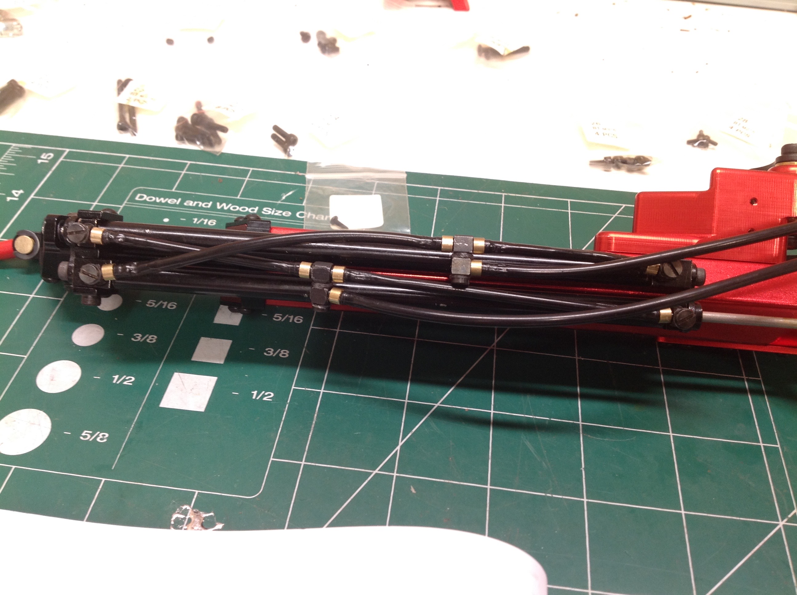
Plumbing those telescoping cylinders together is no small feat. In
fact, the whole process of installing the tubing was a royal pain in
the butt. The tubing is quite stiff and the inner diameter is
smaller than the fittings so you must stretch the hose over the
fitting. Beyond that obvious difficulty, the fittings are tiny and
very difficult to hold without using a tool that may damage them.
There was much cursing and injury before I arrived at the photo on the
left. Because the telescoping cylinders are plumbed in parallel,
the extension and retraction lines each need to split in two before
going into the actuators, and there must be enough extra length to allow
the whole lot to extend with the boom without binding. On the
right I've done the same for the folding cylinder and the lifting
cylinder. These were somewhat easier to plumb but by the time all 6
hoses get routed through the turntable things are getting a bit
confusing.
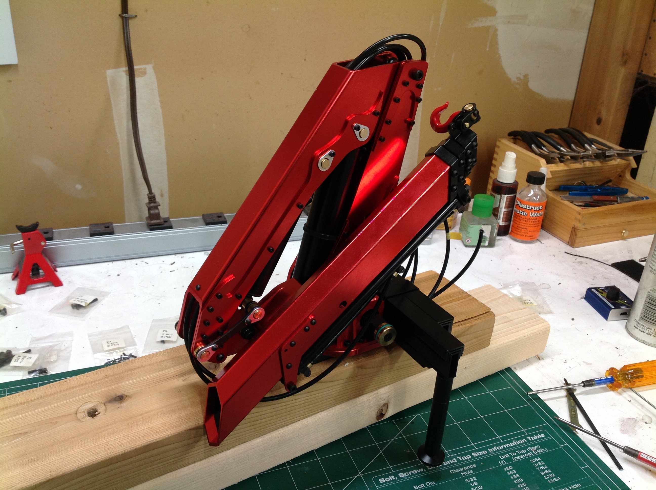
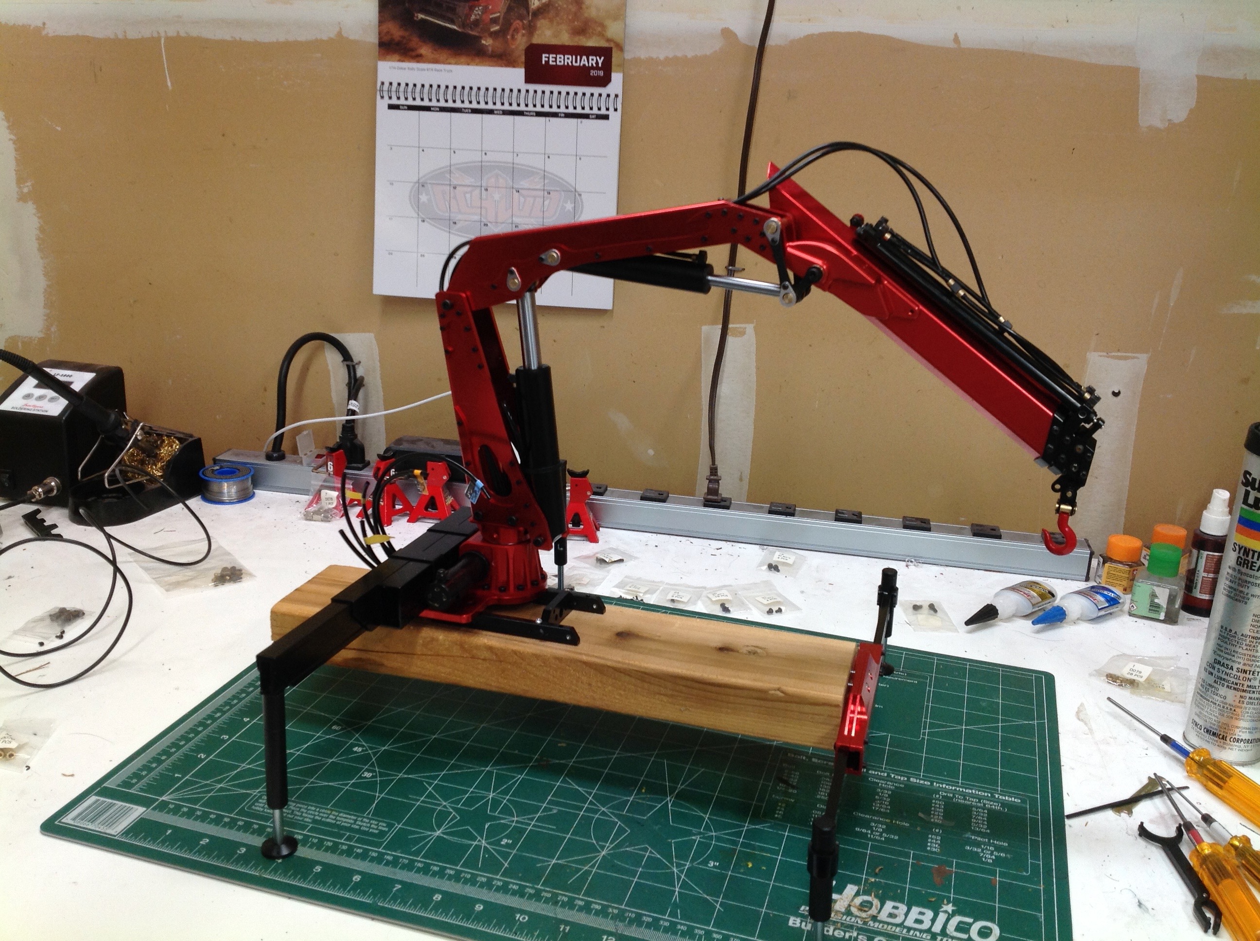
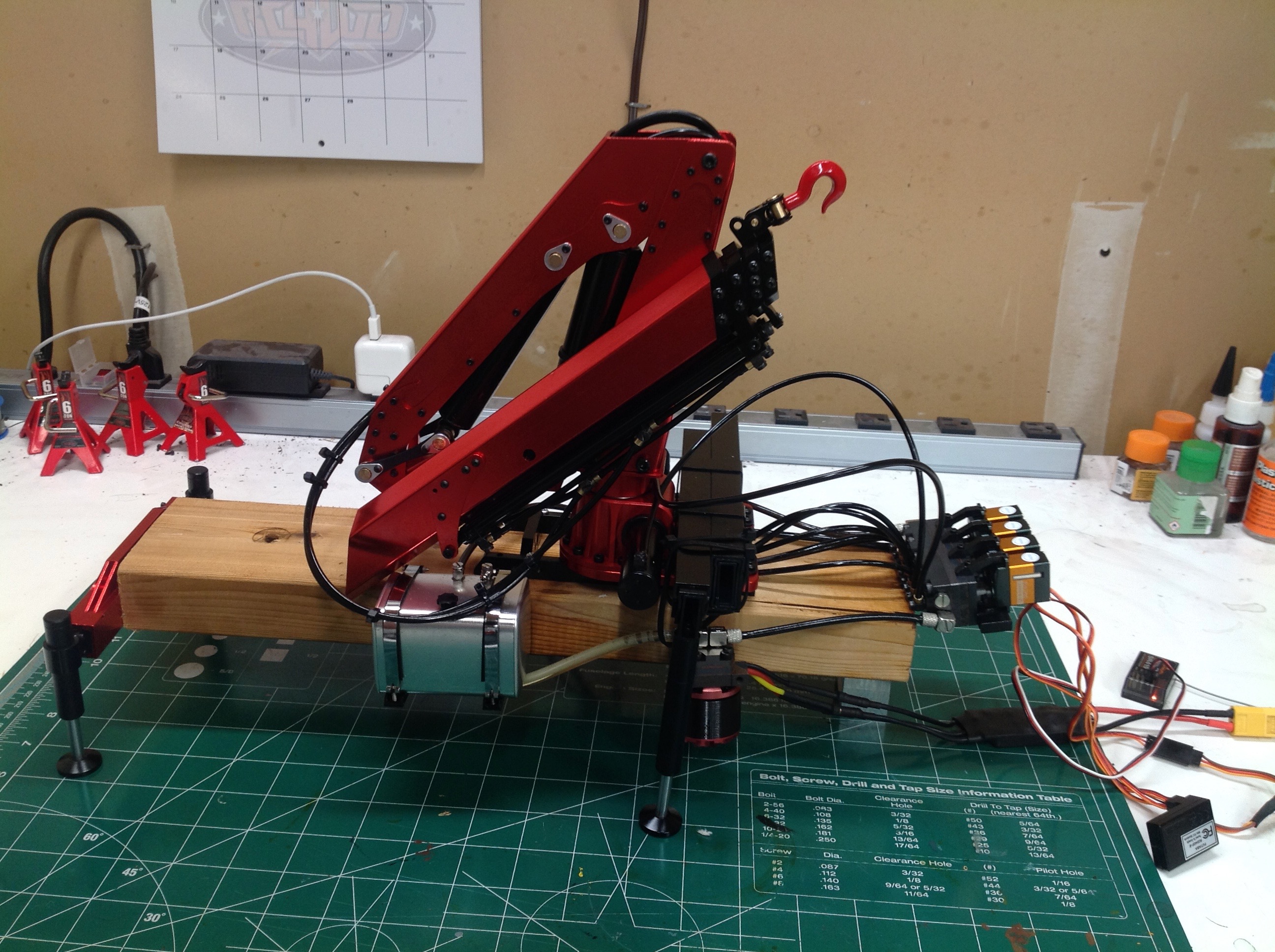
At the time I built this crane I didn't have any truck on which to
install it yet but I really wanted to do a functional test so I just
mounted it to a block of wood. Since the weight can be supported
by the outriggers anyway, this worked just fine as a test
platform. Here I've mounted the crane and outriggers but none of
the hydraulic system has been installed yet.
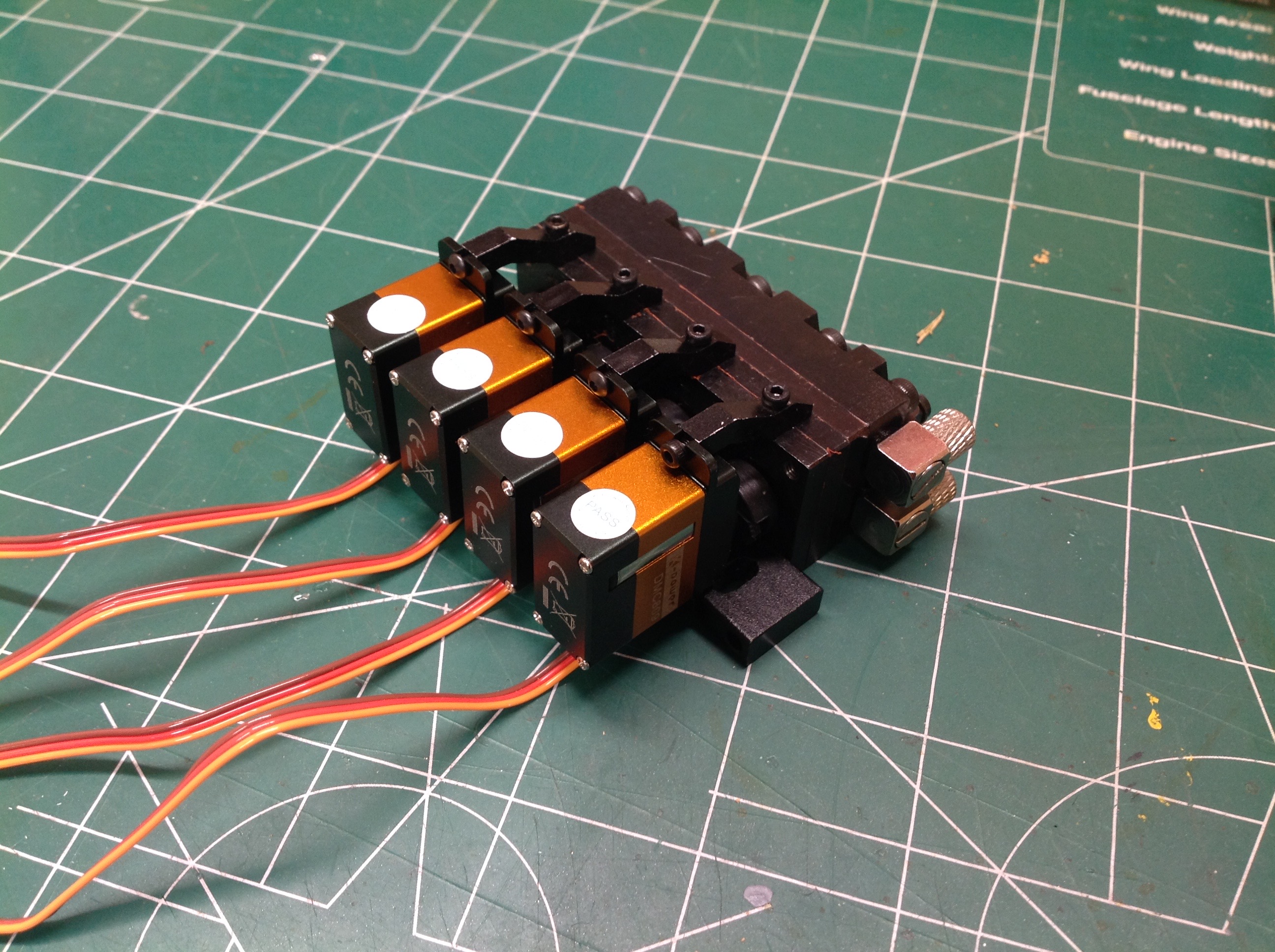
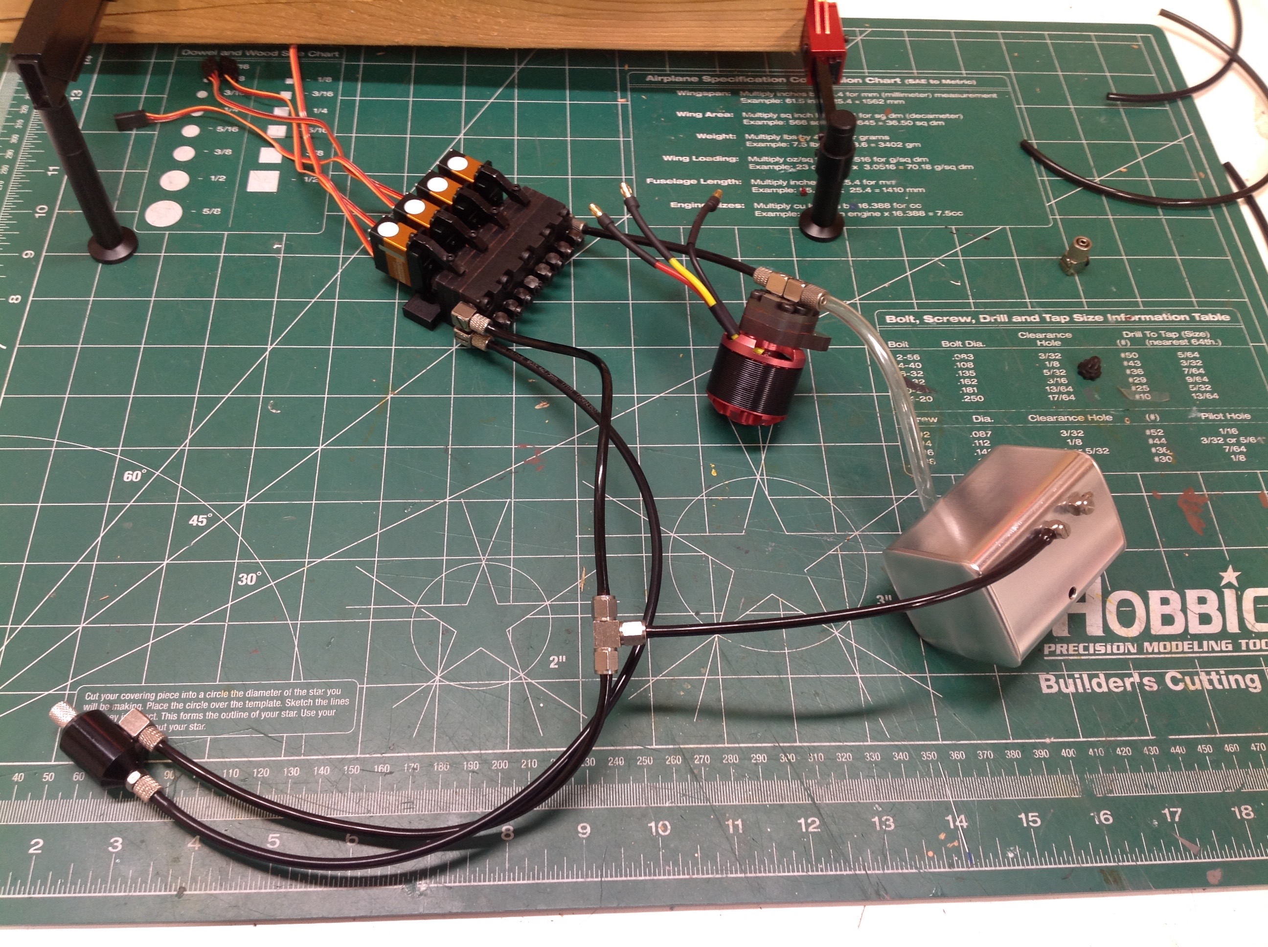
The control valve / distribution block is a thick slab of steel made up
of multiple layers with 4 proportional valves and mini servos. The
servos came with the kit which is good because it guarantees they will
fit properly. This block has 8 outputs: one each for retraction
and extension for 4 channels. There are 3 additional
connections. One is the high pressure input from the pump which
runs straight through to the other side and through a pressure relief
valve. This adjustable valve controls the maximum pressure in the
system. Too low and you won't have enough power to lift
anything. Too high and you'll blow off connections. The
presence of the relief valve allows the pump to run continuously even
when no flow is needed because it just flows through the relief
valve. The downside to this is that is churns up the fluid and you
get a lot of foam. The last connection is return pressure which
runs back to the reservoir. The reservoir is disguised as a fuel
tank so looks great on the side of a truck. The pump runs off a
dedicated brushless outrunner motor with its own 60A ESC.
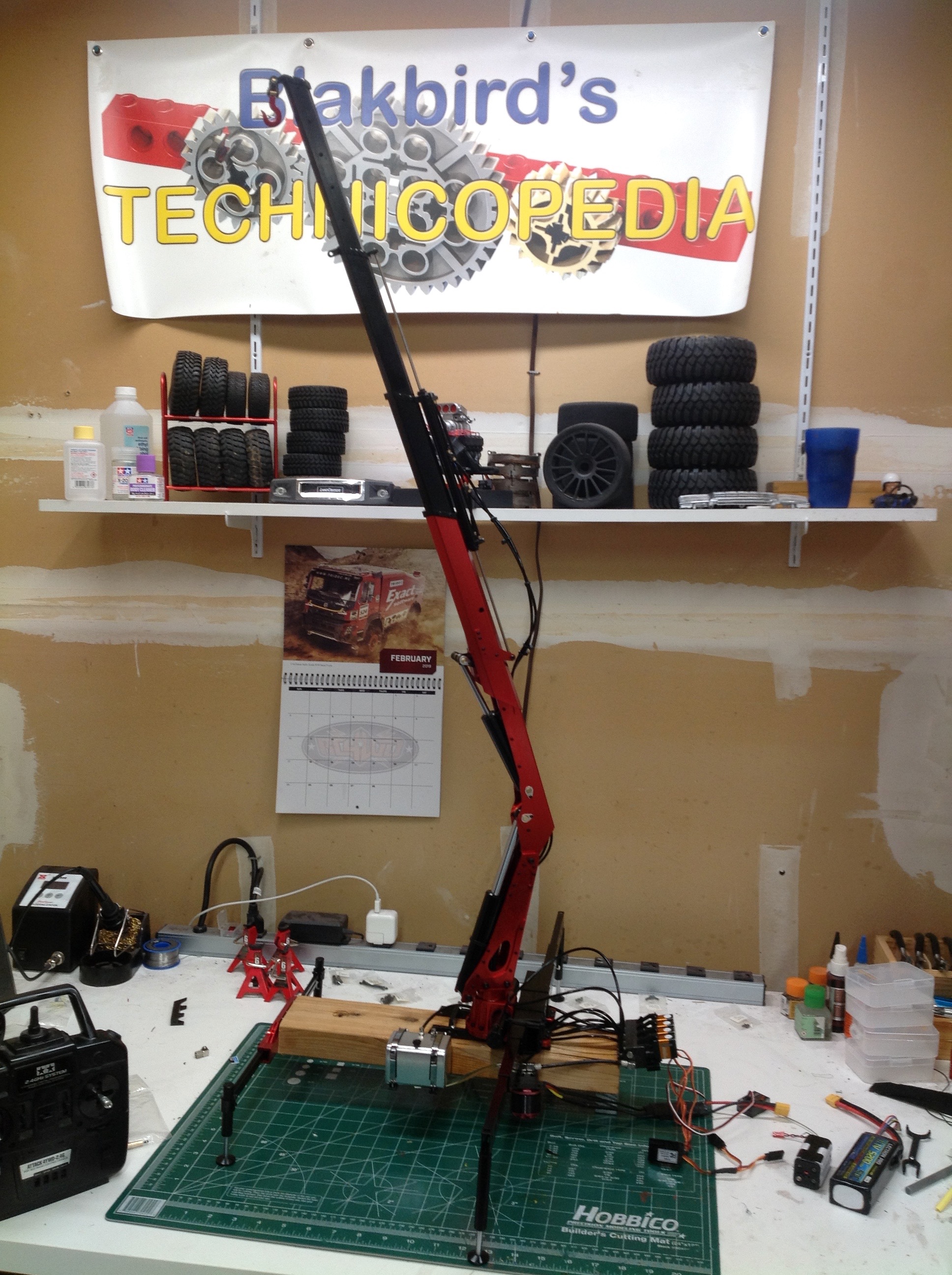
Success! After troubleshooting plenty of leaks and wasting almost a
liter of oil, I have a working hydraulic crane mounted to a block of
wood. It has a surprisingly large capacity to lift weight even at
full boom extension.
©2019 Eric Albrecht