MAN TGX Project
Page 3: Crane Installation
The crane is specifically made to be installed on Tamiya 1/14 scale
trucks, but that doesn't mean installation was quite as simple as just
bolting it on. A number of modifications and adjustments needed to
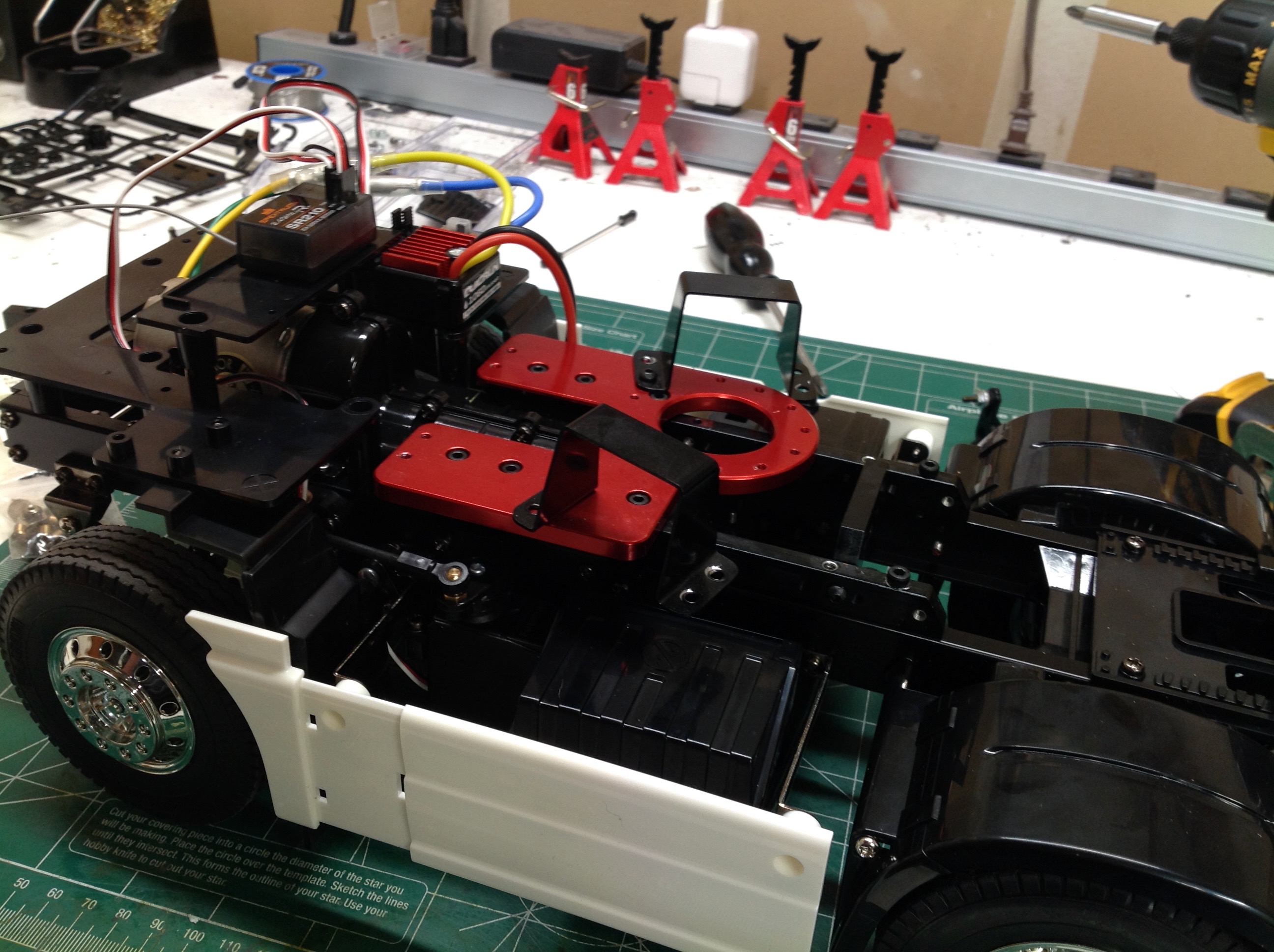
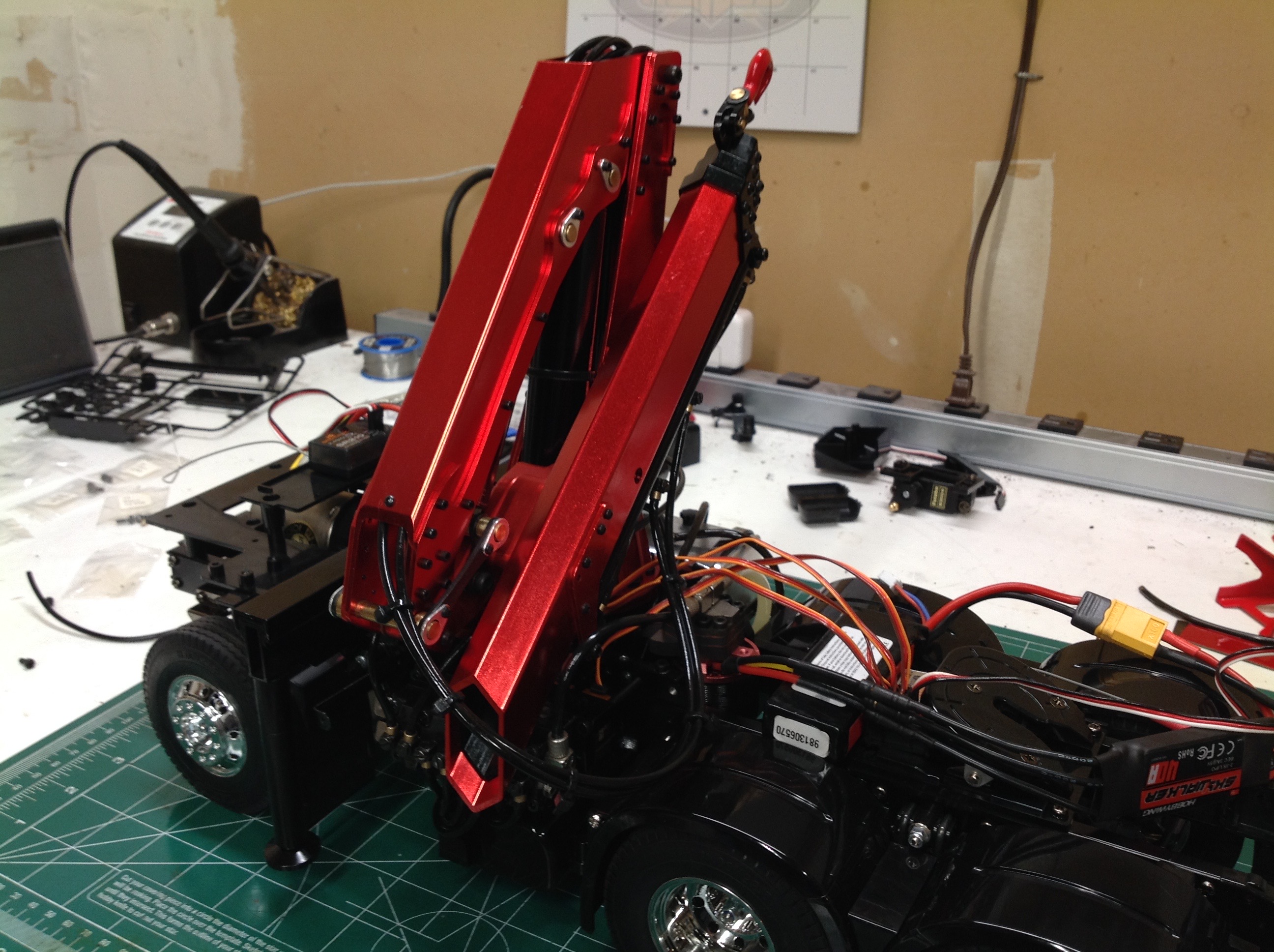
be made. It started out well enough. The picture on the
left shows the crane base bolted to the frame rails. This went
pretty smoothly except that I needed to remove an oil tank screwed to
one of the cross members which was right beneath the large hole where
all the hydraulic hoses will pass. Removing that was a lot harder
than you might think since there was no access to the screws with the
model built. I would have had to disassemble the whole chassis to
access it so I just cut it out with a Dremel. The right hand image
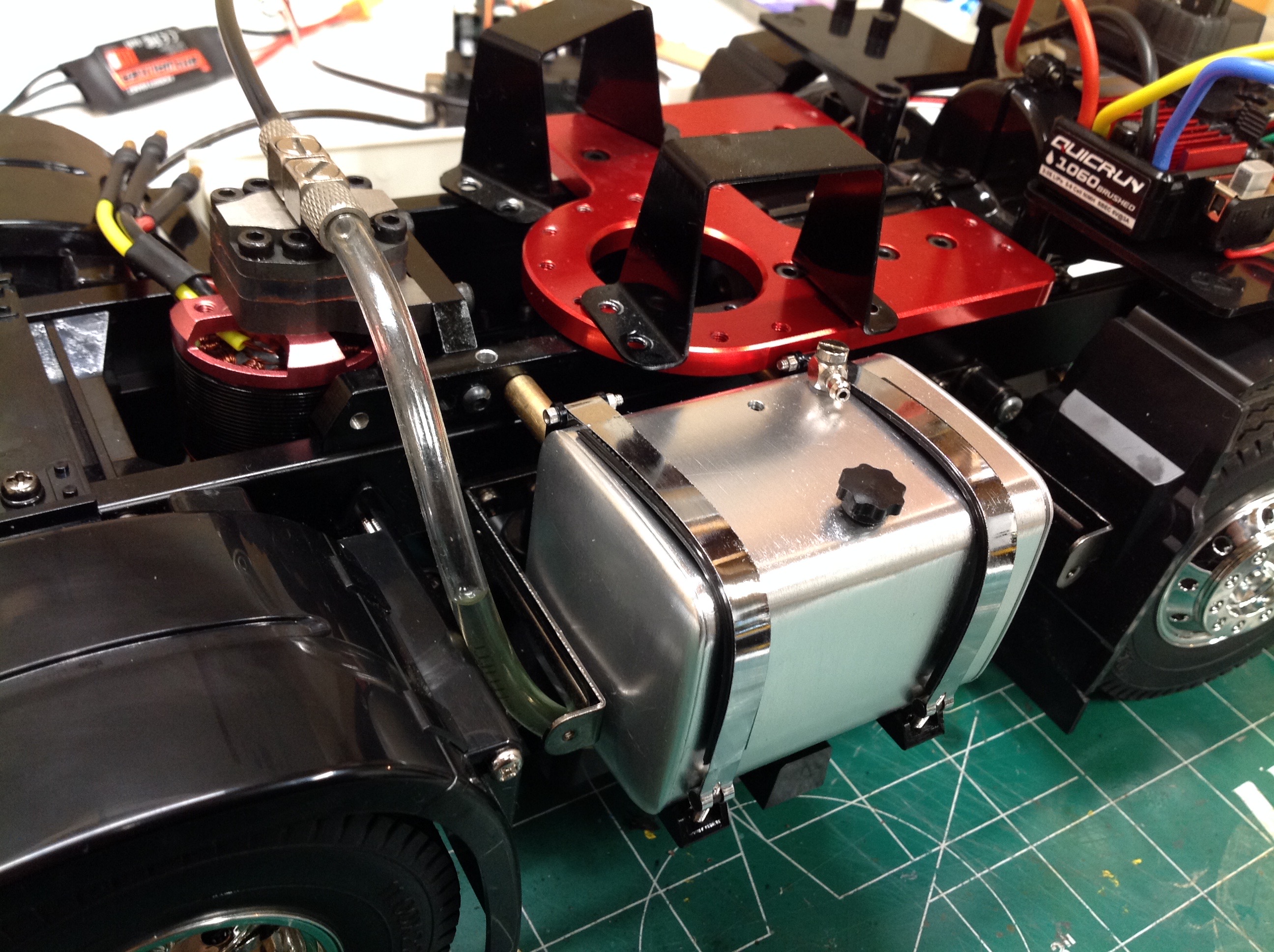
shows the installation of the hydraulic reservoir. This required
removal of a plastic fuel tank that served as a housing for a
Multi-Function Control Unit which means I will not be able to use an MFC
on this model. Between the frame rails you can see the hydraulic
pump and it's brushless outrunner motor. The pump motor is capable
of running on 3s, but I have found that 2s offers plenty of speed.
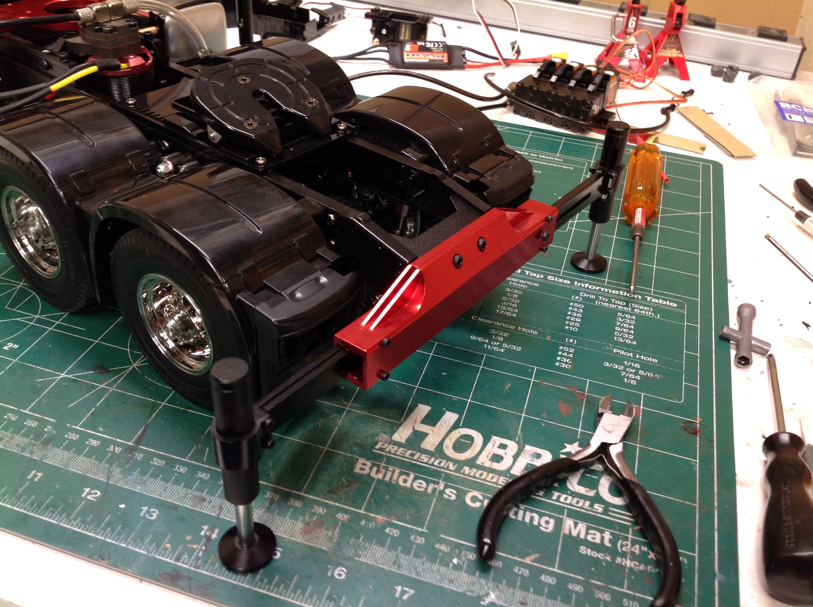
Next I installed the outriggers, front and rear. The huge front
outriggers sit right behind the cab on top of the frame. The rear
outriggers take the place of the rear bumper and partially obscure the
tail lights which doesn't seem ideal. The outriggers are strong
enough to hold up the whole chassis with the wheels slightly elevated
from the ground and offers plenty of stability for use of the crane.
Once the main crane arm is bolted on the chassis gets very heavy
indeed. In fact, all of the suspension is bottomed out. This
is not such a big deal in the rear but I'd like to find a way to
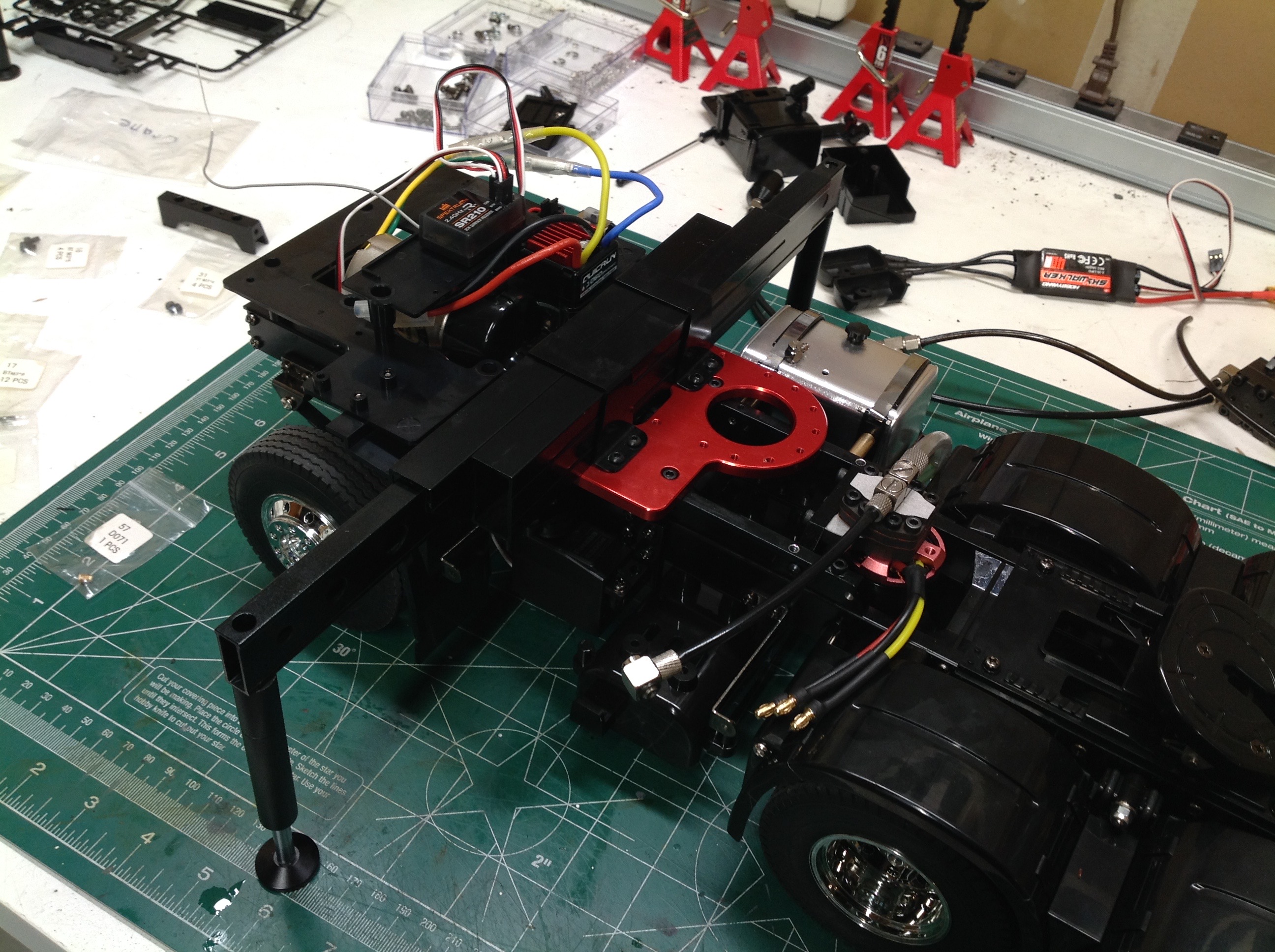
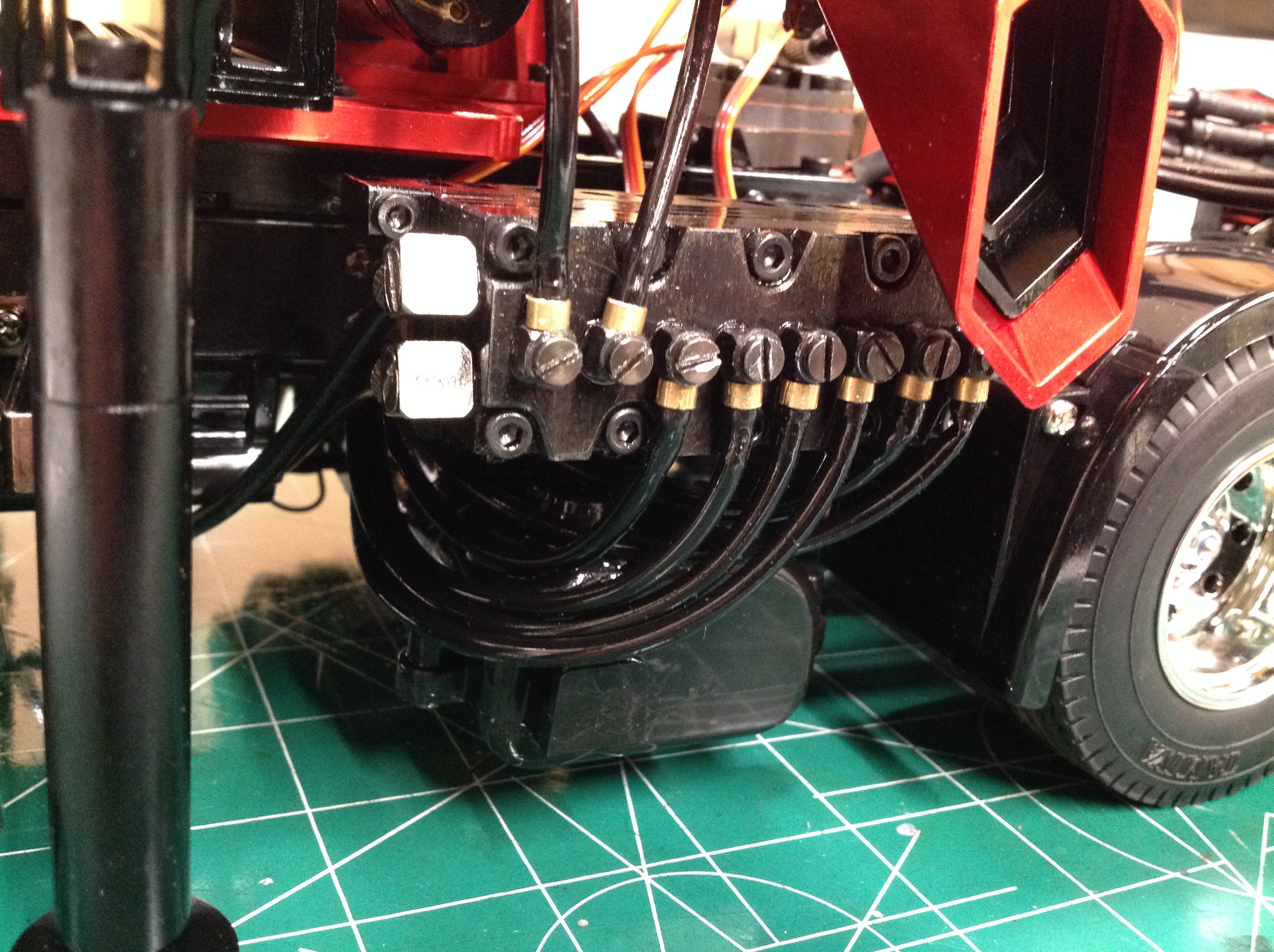
stiffen the front end. The left side of the chassis opposite the
hydraulic tank becomes the home of the valve block as shown on the
right. Three circuits run down under the frame rails and then up
through the hole in the crane. The other circuit runs up to the
slewing cylinders. Supply and return lines have to find a home
somewhere between.
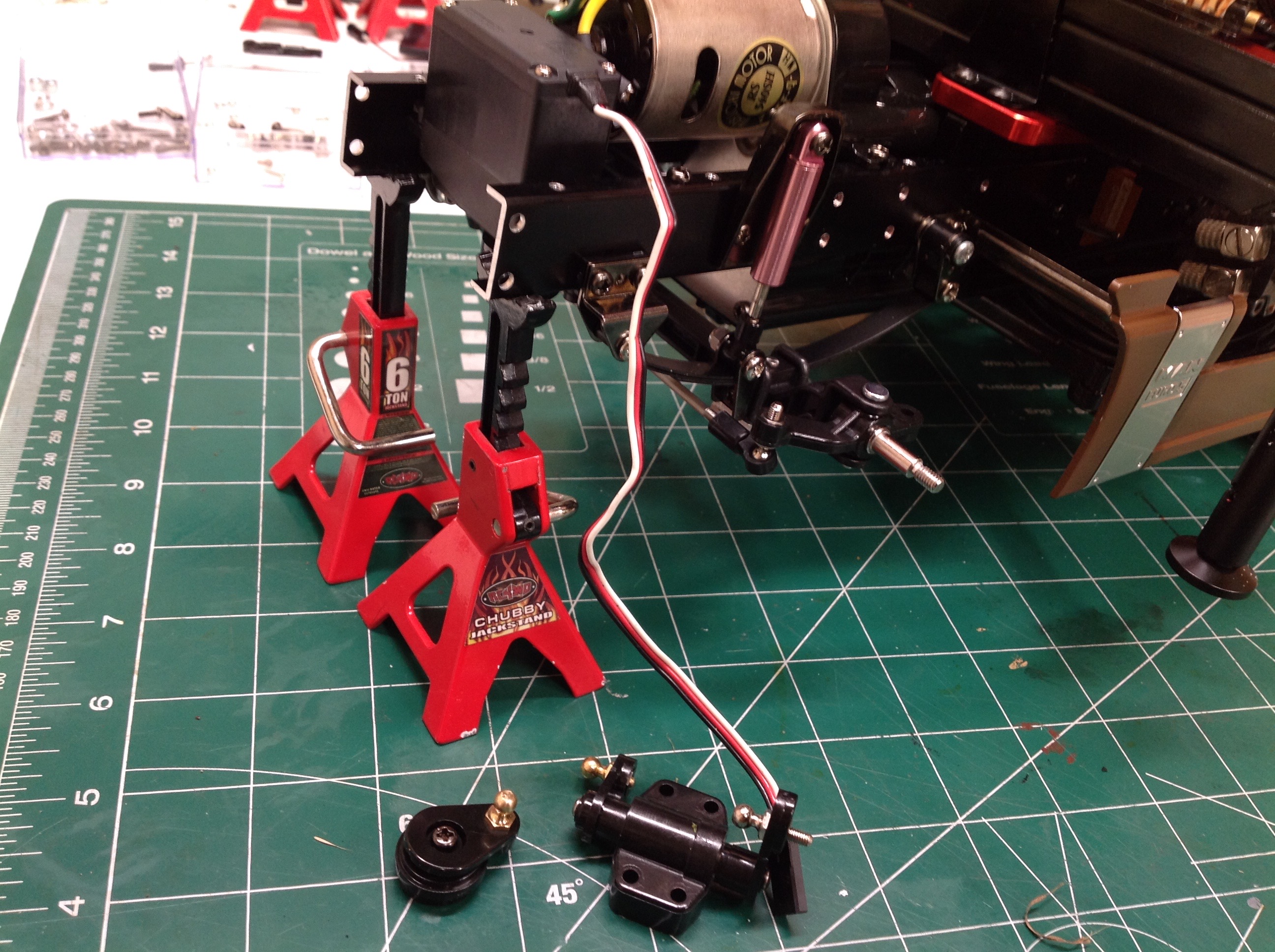
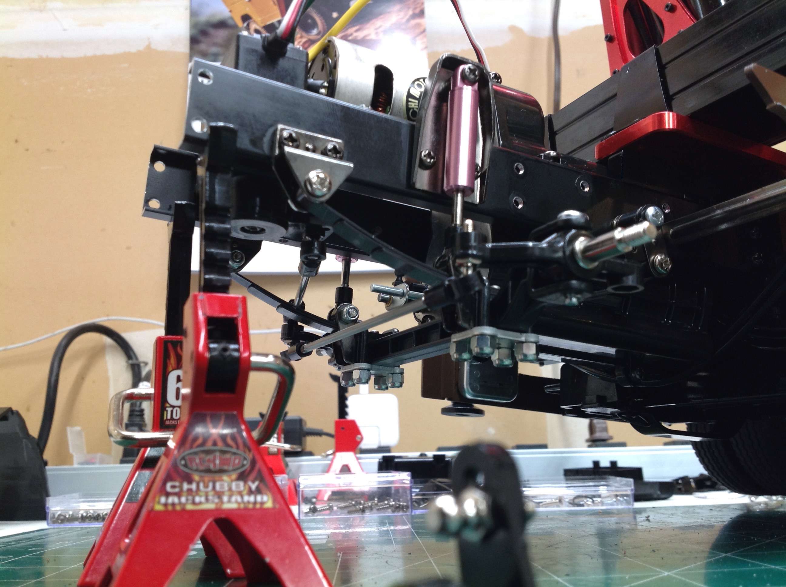
The cabover style trucks use a steering servo mounted on the left side
of the chassis. This will no longer work because the hydraulic
valve block occupies that space. I had to move the steering servo
up to the front ahead of the motor in the space normally used for the
transmission shift servo. This means I won't be able to shift the
3-speed transmission. This location was not really meant for a
steering servo so I had to get creative with the links. You can
see on the right how I routed the steering link just above the leaf
spring. I also used a high torque servo saver to handle all the
weight over the front wheels.
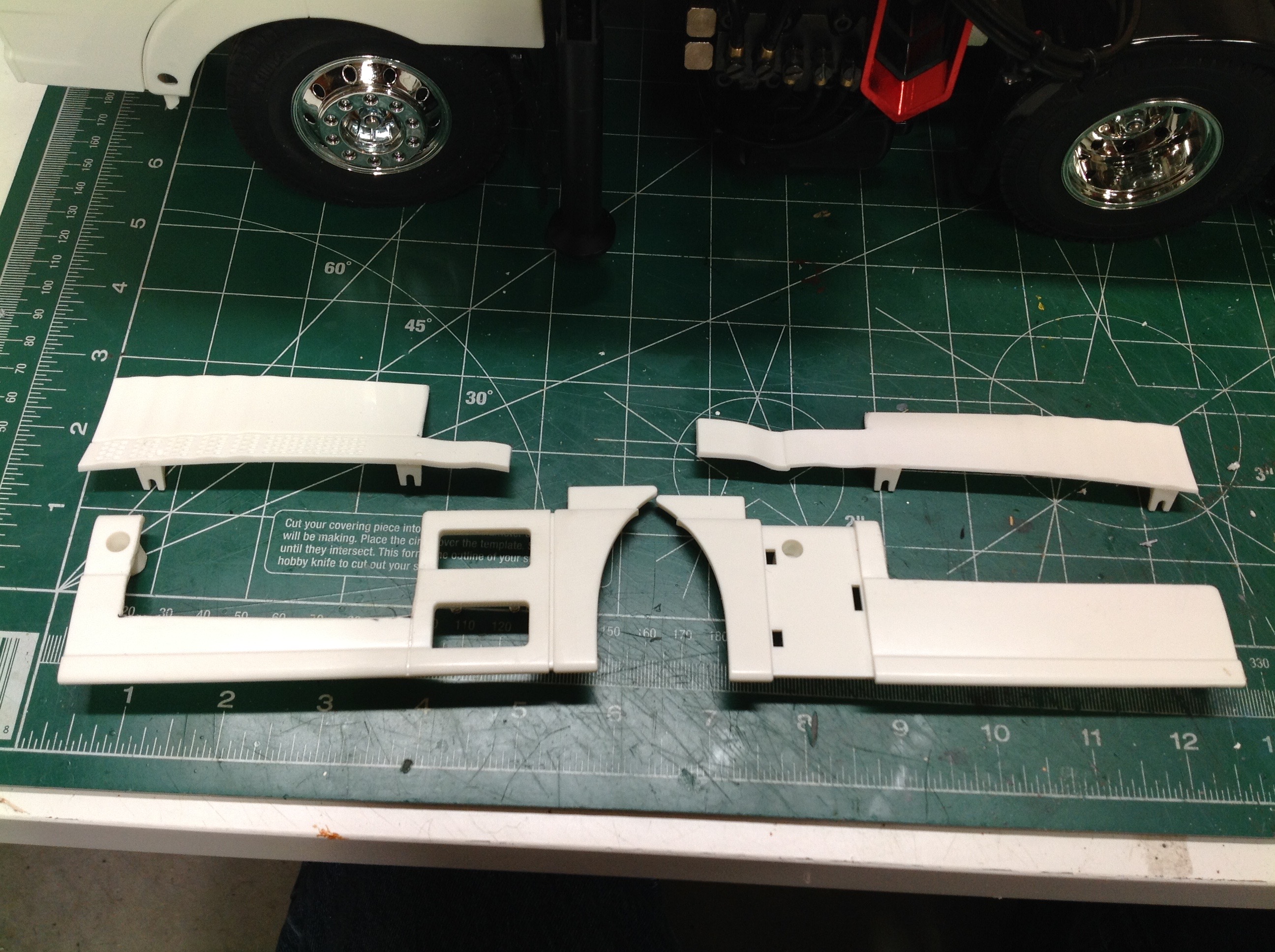
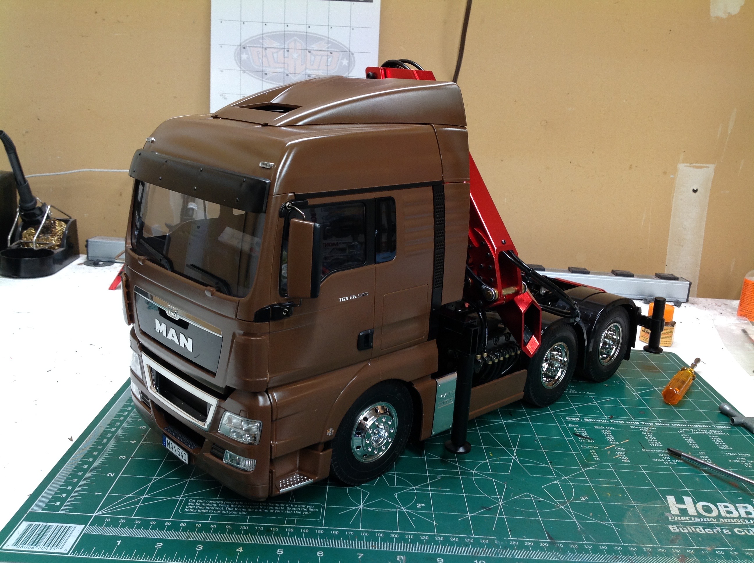
The MAN TGX uses fairings and spoilers behind the cab and along the
frame. None of them will fit directly anymore because they
interfere with the various crane components. One way to handle
this would be to just leave them off, but I think this compromises the
look of the truck too much. Instead I trimmed the parts for
clearance as shown on the left (all of these started out roughly
rectangular). The photo on the right shows them all
installed. I think the original appearance of the truck was
maintained fairly well.
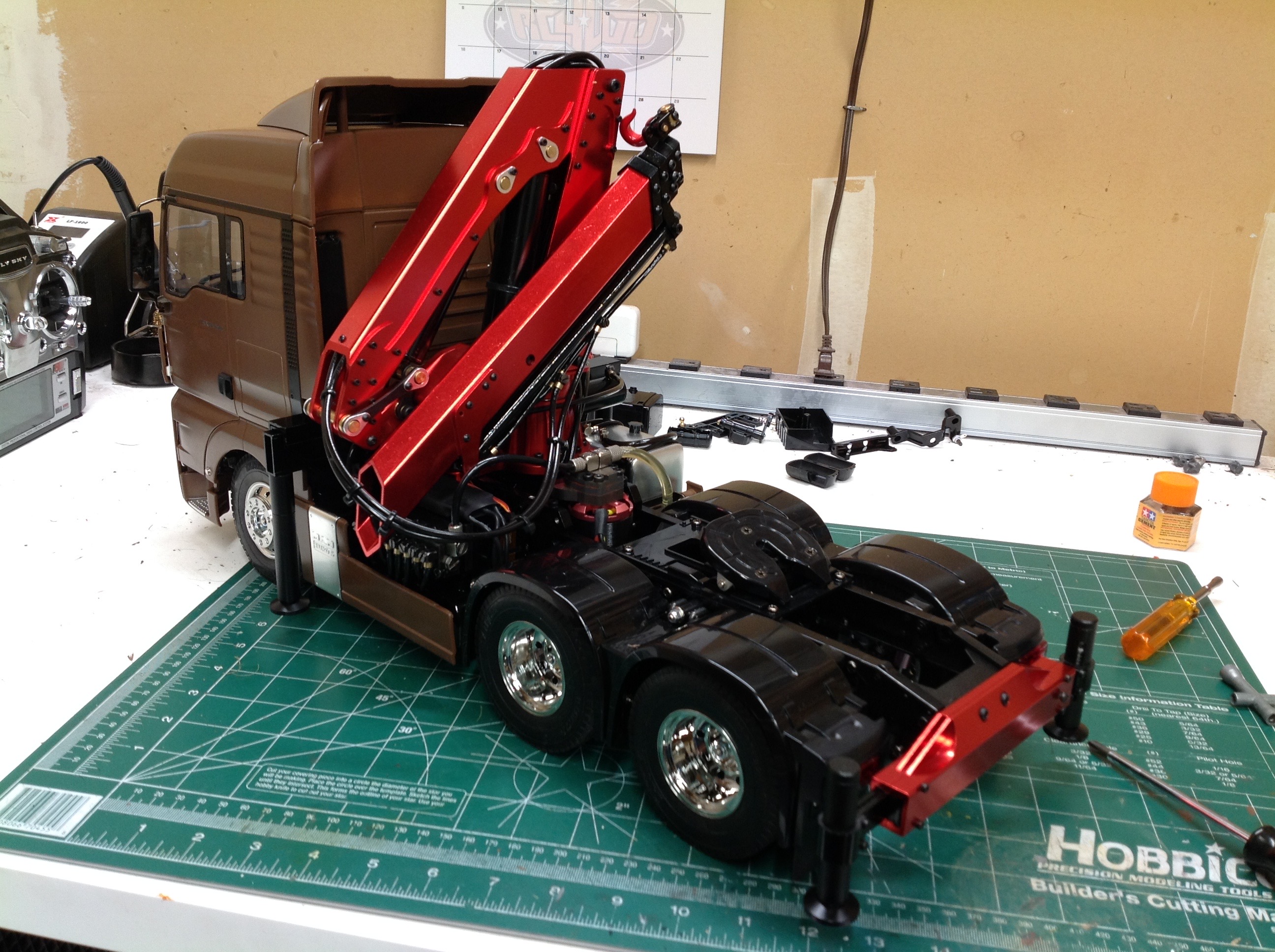
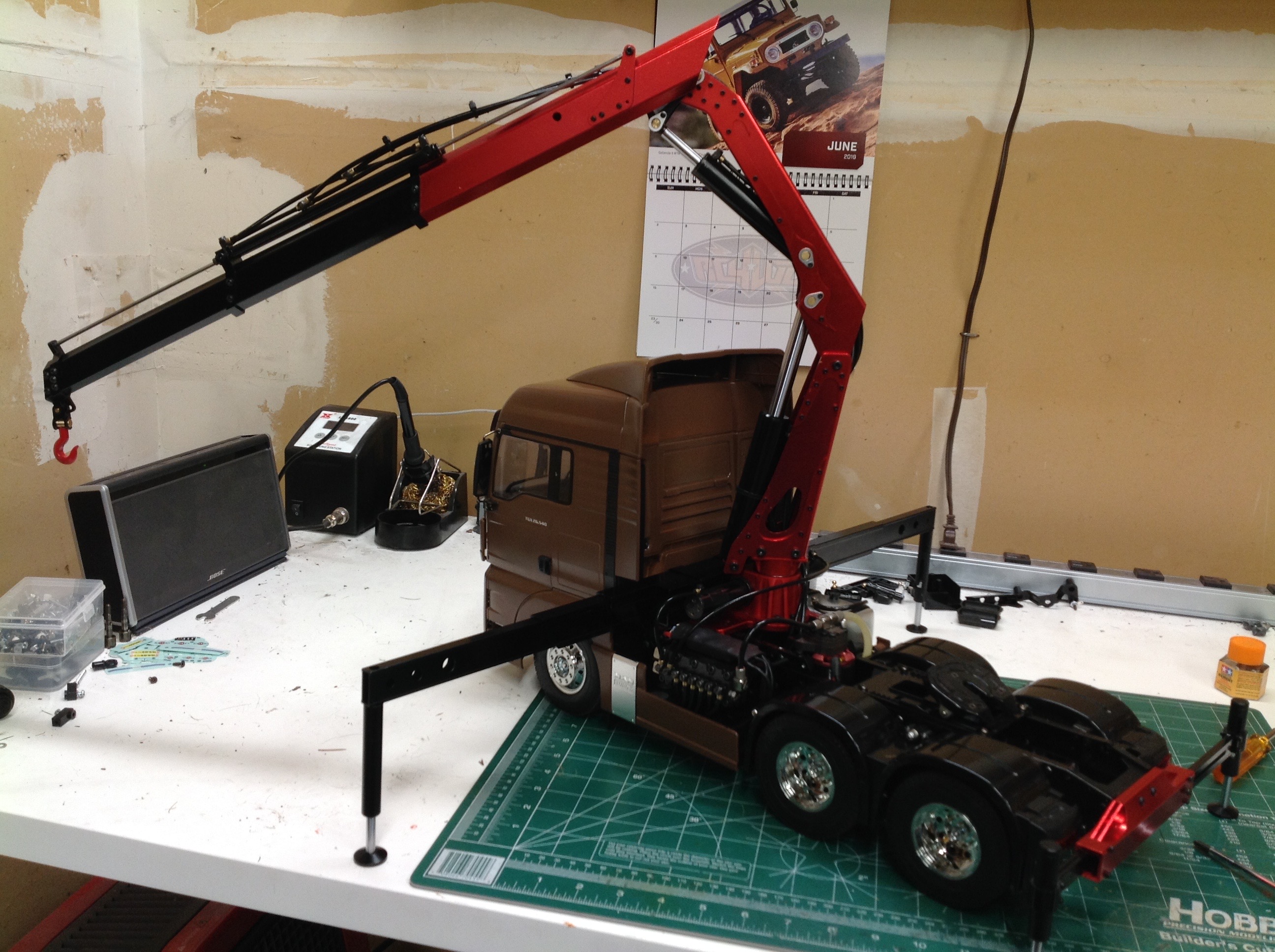
Here's the completed crane install both stowed and deployed. It
looks like it belongs there which is what I was going for. The
truck still drives well even with all the weight. The crane uses
it's own ESC which I have wired in parallel to the same battery. I
use my normal 4-channel transmitter for driving the truck and another
5-channel twin stick transmitter for operating the crane. The 5th
wheel is still accessible but doesn't have much clearance for the front
of a trailer.
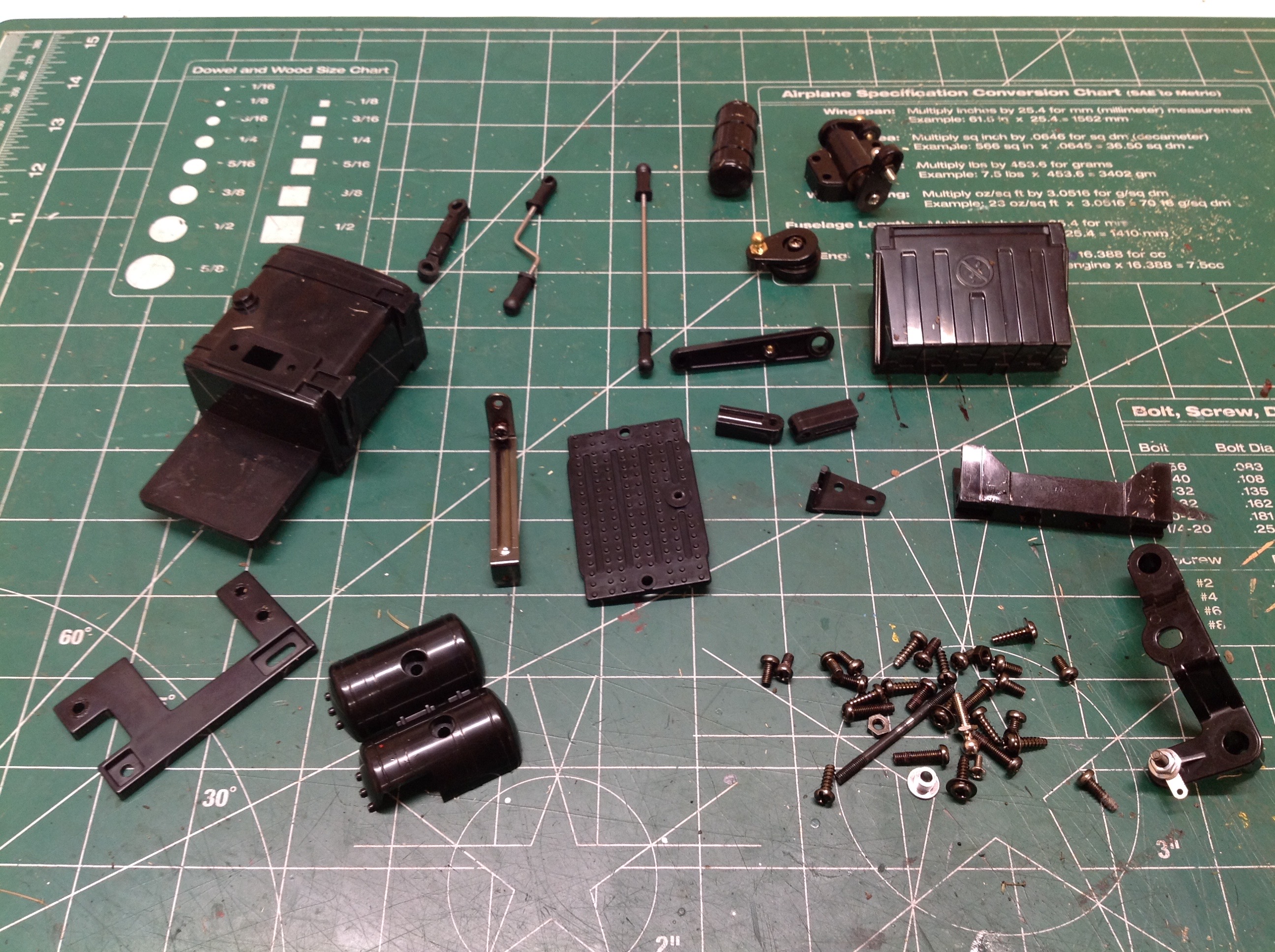
This picture shows all the parts of the stock truck which had to be removed to make room for the crane.
©2019 Eric Albrecht