Tamiya Mammoth Dump Truck Project
Page 2: Building the Chassis
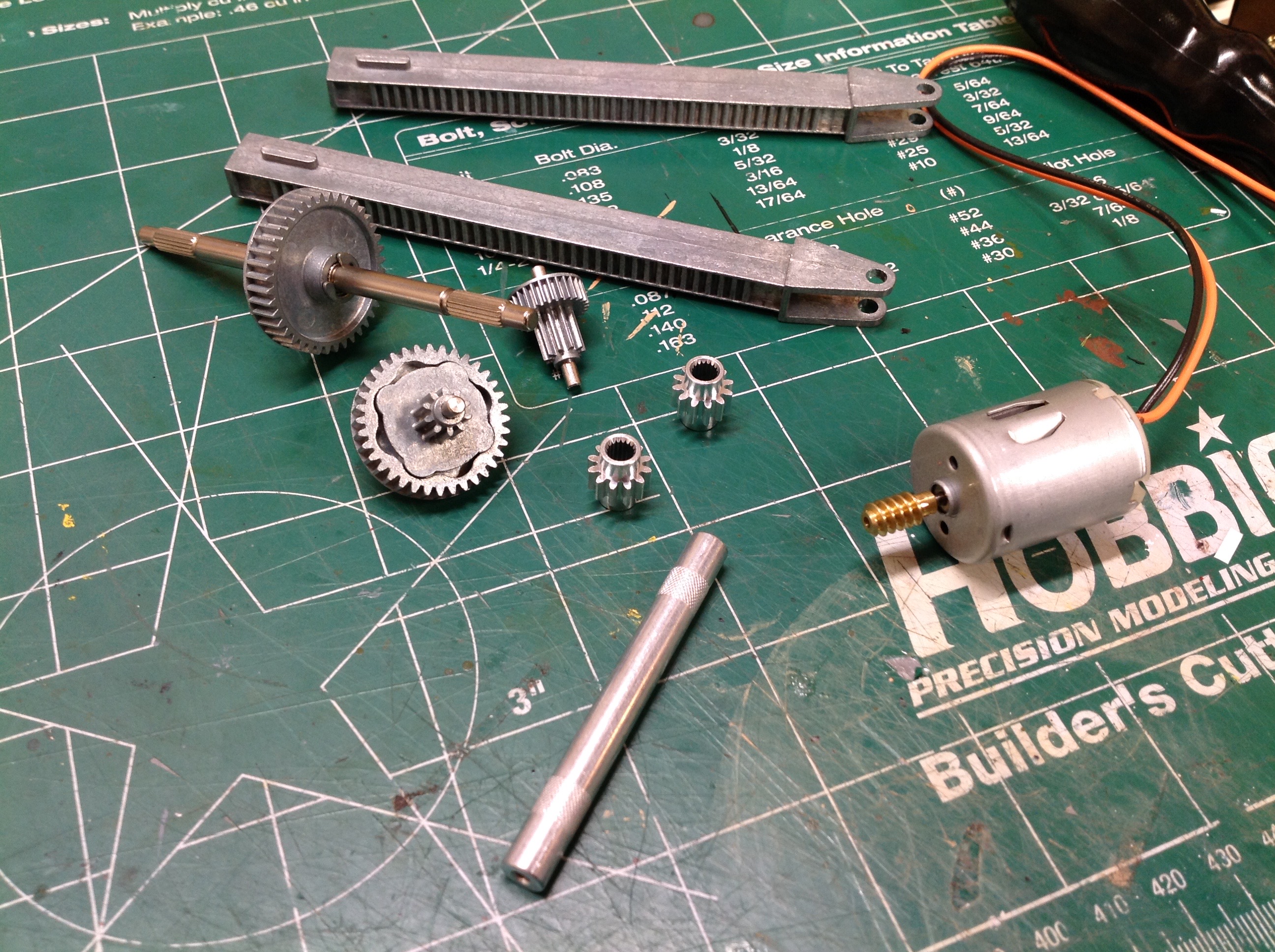
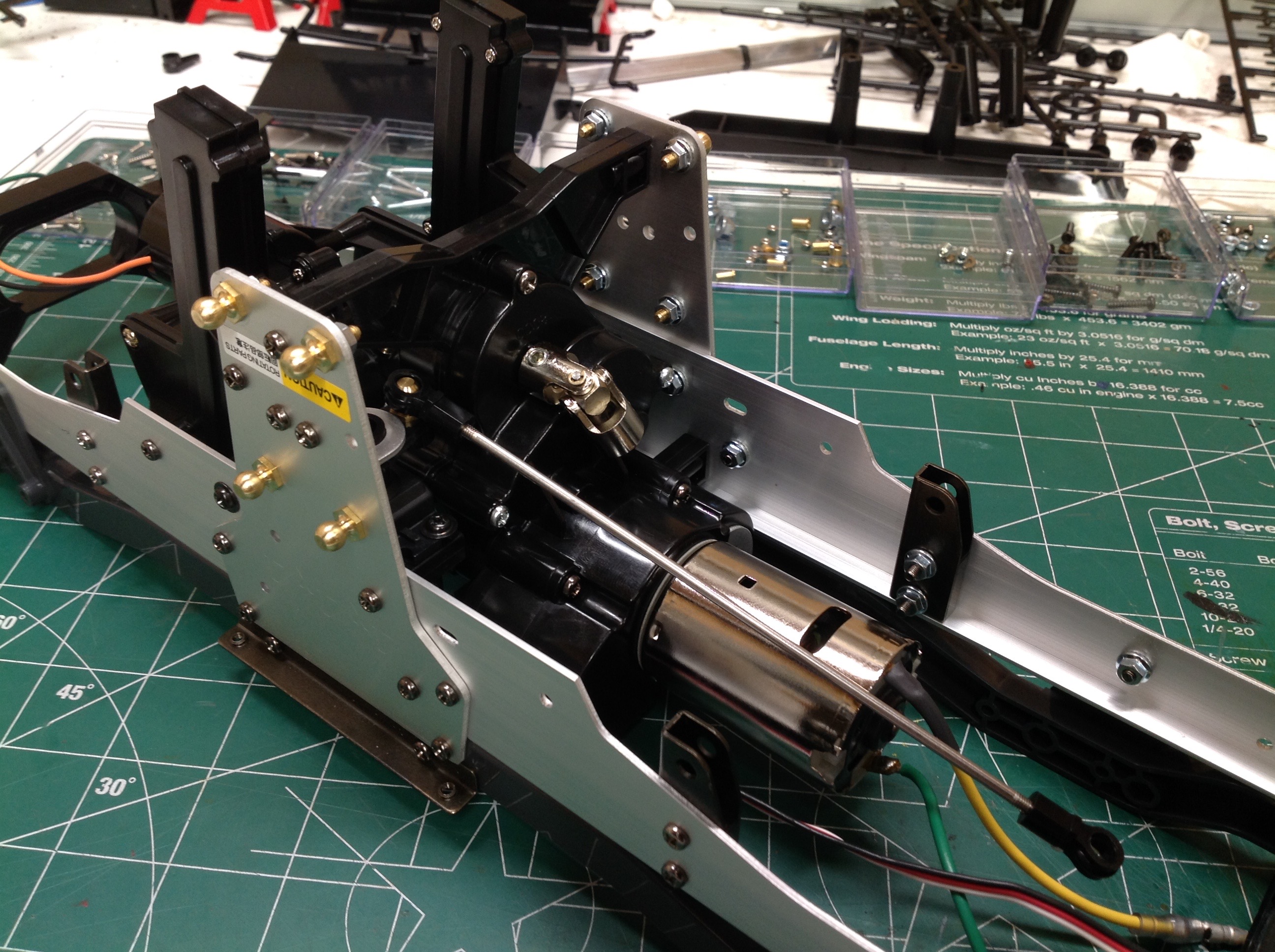
The lift actuator needs to be built before we get started on the chassis
because it sits between the chassis rails. As you can see, all
the gears for the lift system are metal. The motor is 370 sized
with a worm gear attached. You can see that the gear second from
the left has a lobed driver which can theoretically act as a clutch if
too much torque is applied, but I've never slipped it.
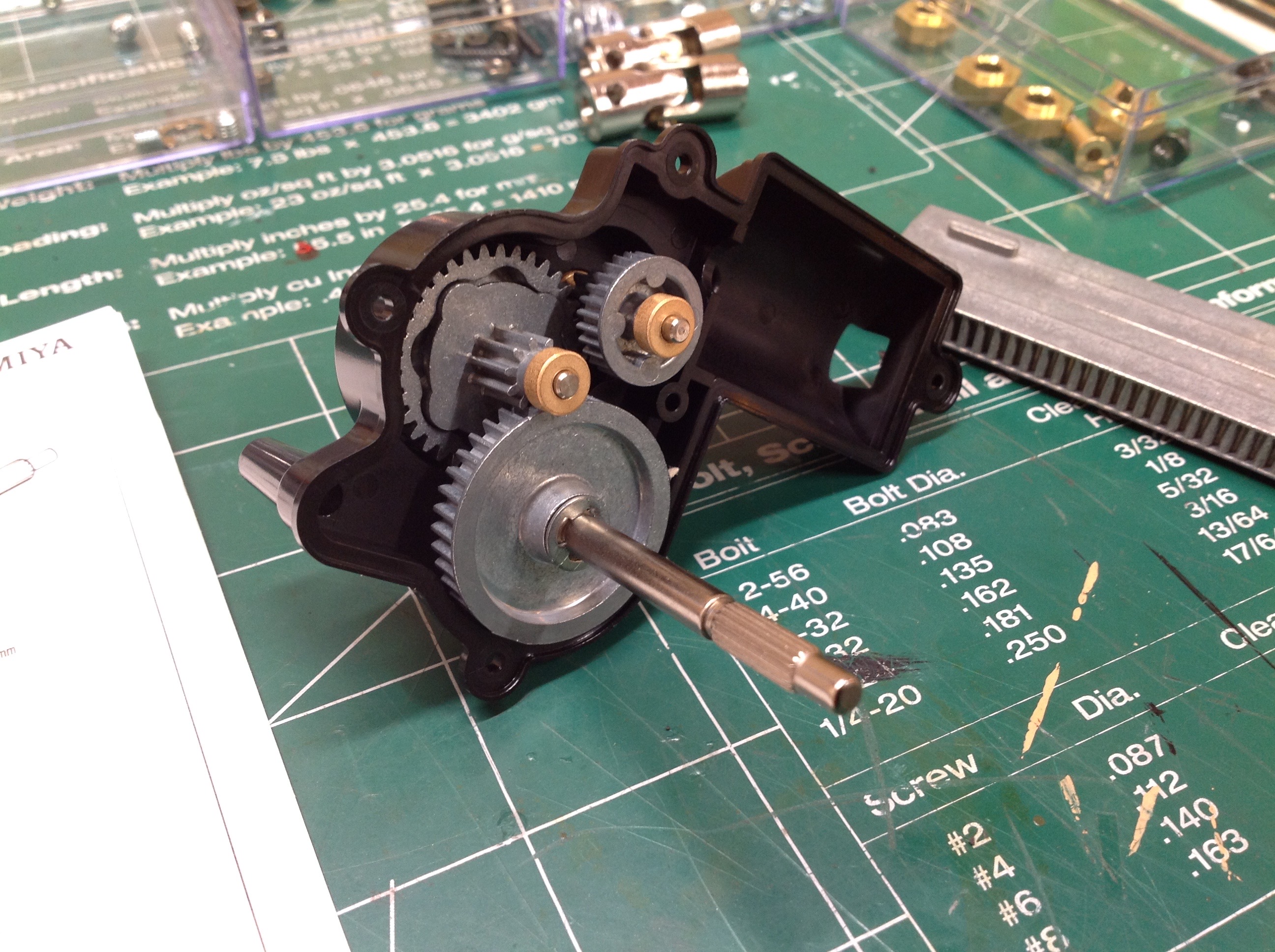
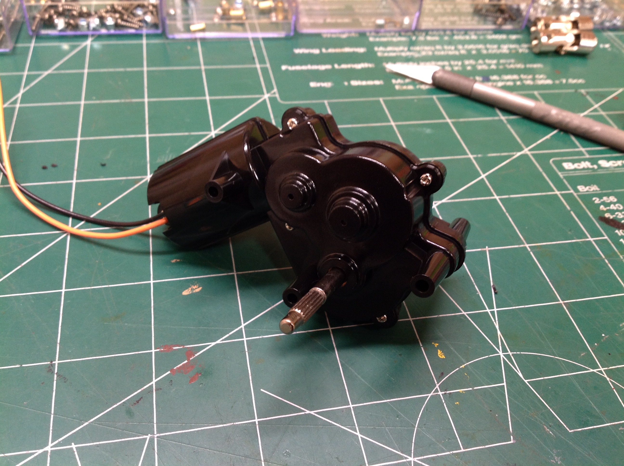
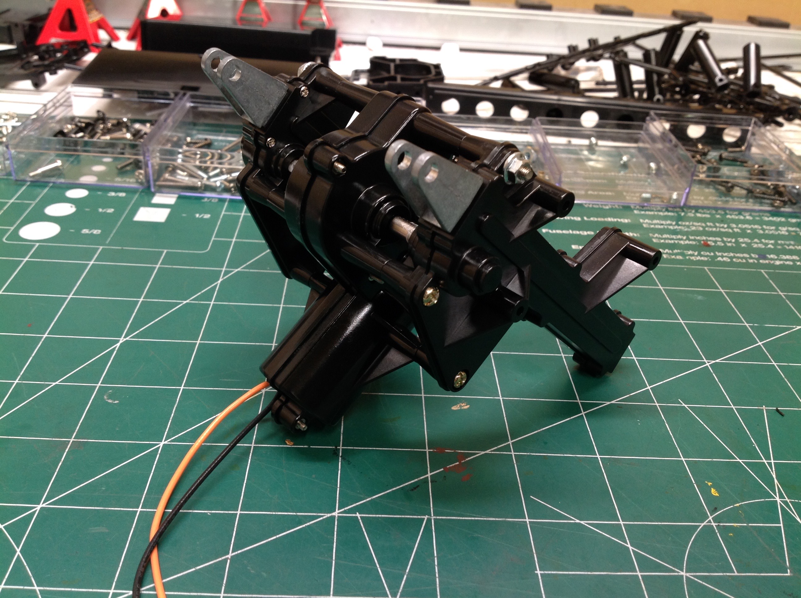
Here is the arrangement of gears inside the gearbox. The motor
will insert from the right. The protruding shaft is output.
There are 3 total stages of reduction. The number of teeth per
gear is not listed in the instructions and there are no plan views of
gears B and D to count so I can't calculate the total reduction, but it
is considerable. There are metal bushings here, but I thought they
were adequate for this application so did not replace them with ball
bearings. The completed gearbox is shown on the right.
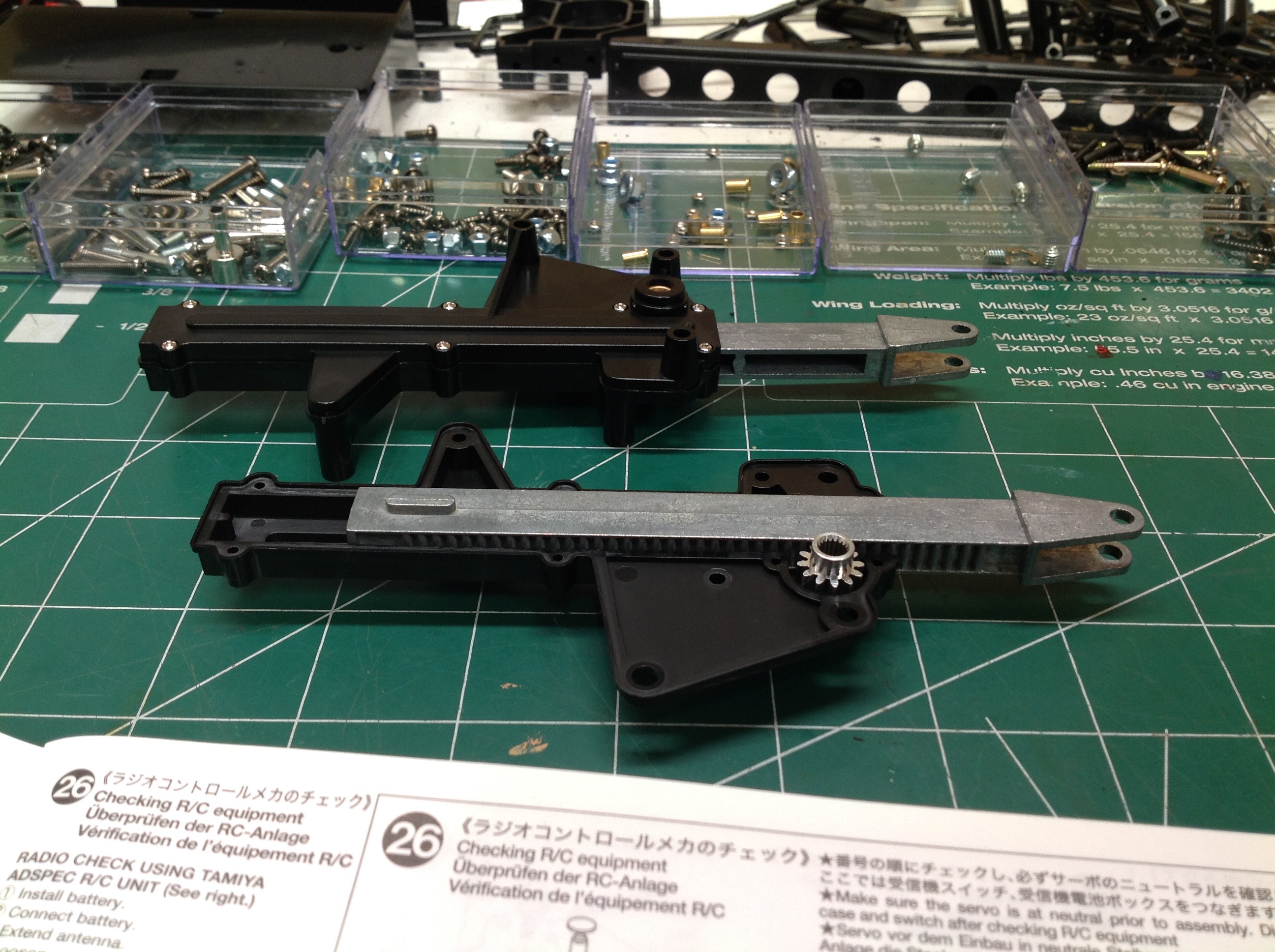
The lift actuator uses a dual rack and pinion system. The output
shaft of the gearbox will drive the small pinions shown which translate
the metal lift racks. This layout is only possible because the
Mammoth is so tall. When retracted, these racks hang far below the
chassis.
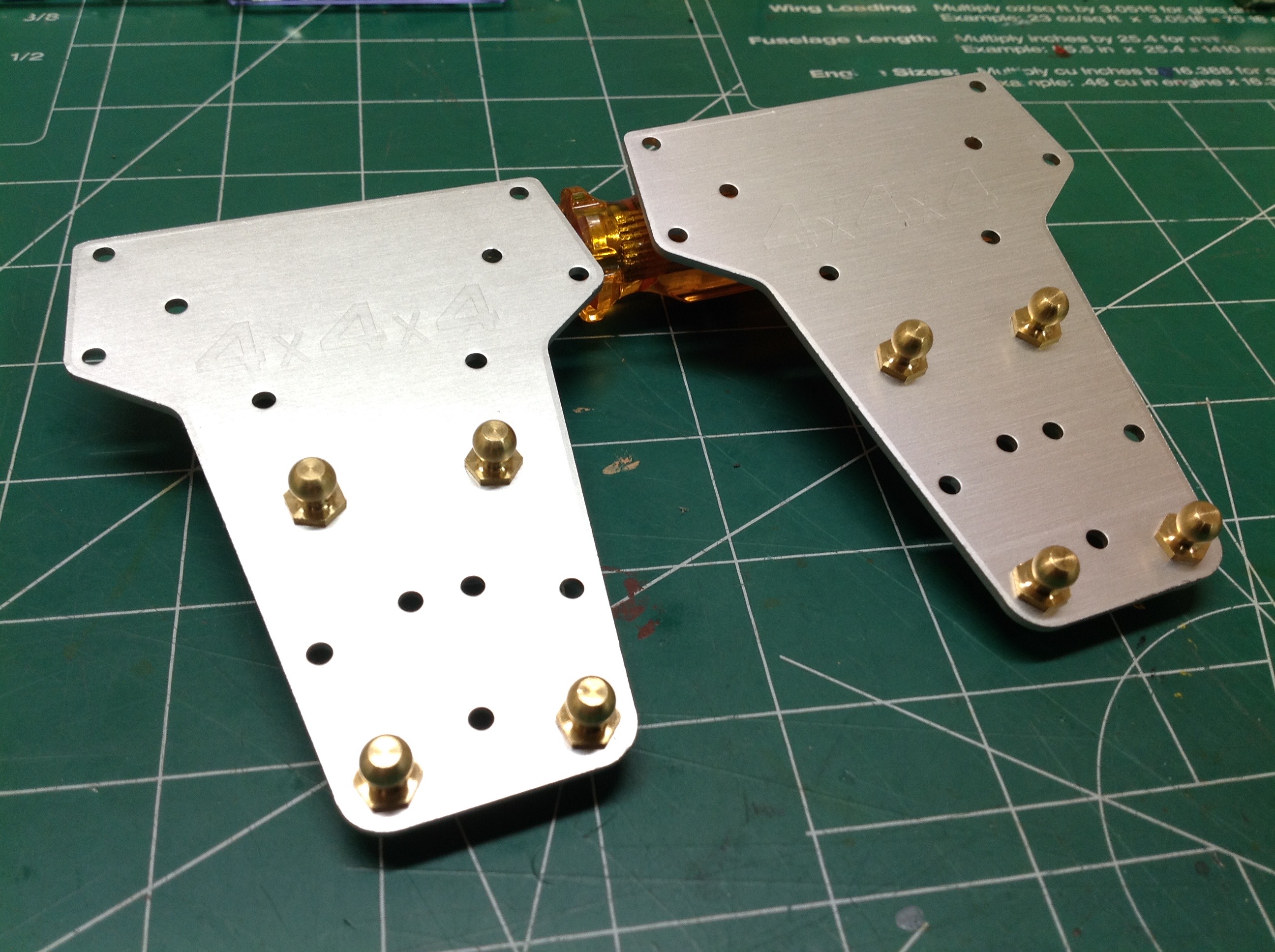
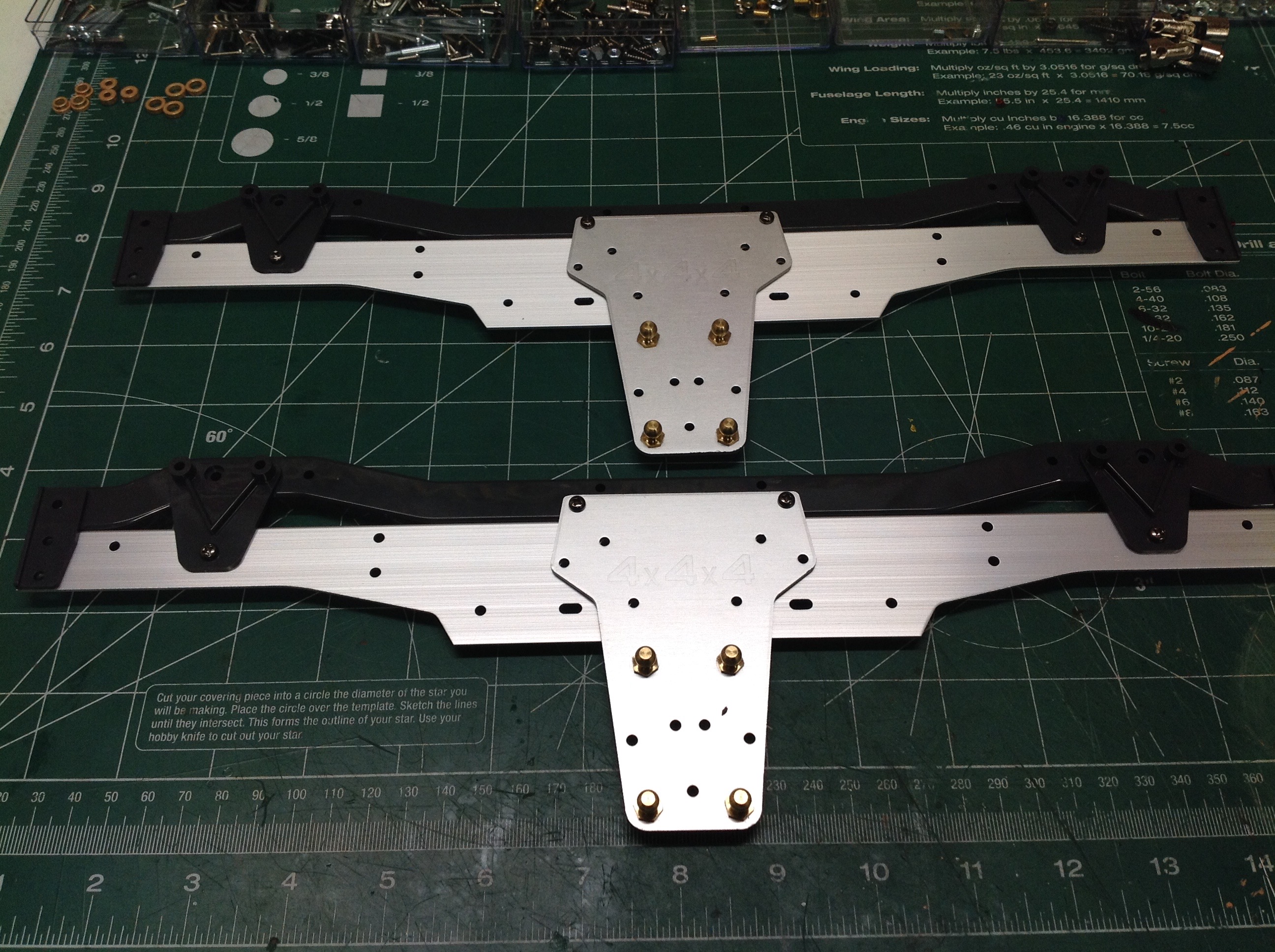
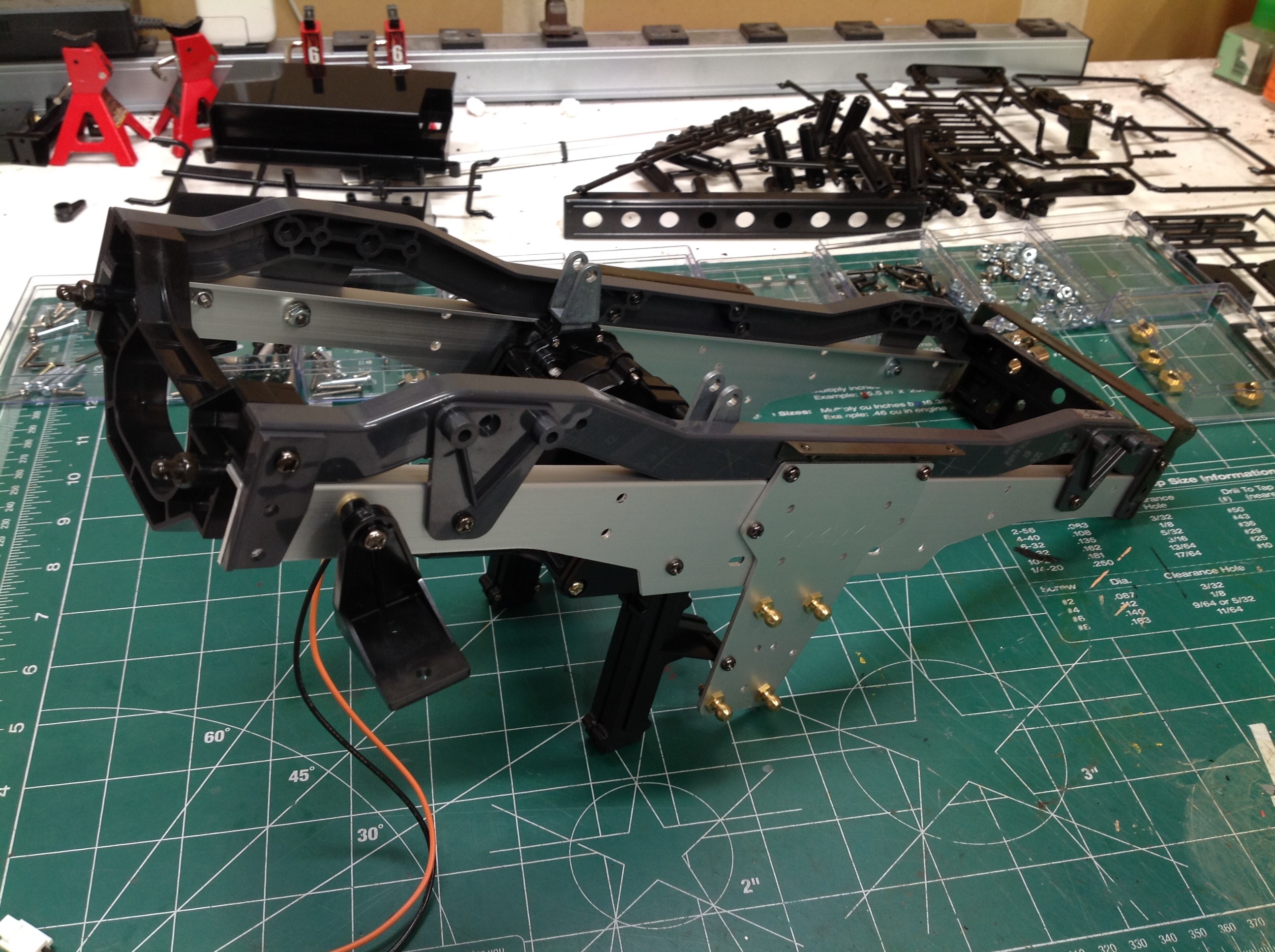
The chassis is built using a TVP (Twin Vertical Plate) support
system. The black chassis rails shown on the right are plastic,
but the huge supports under then are aluminum. The long vertical
aluminum plates are supports for the suspension links. You can see
"4x4x4" etched into the plates from the Juggernaut, but it is not
correct for the Mammoth since we don't have rear steering here.
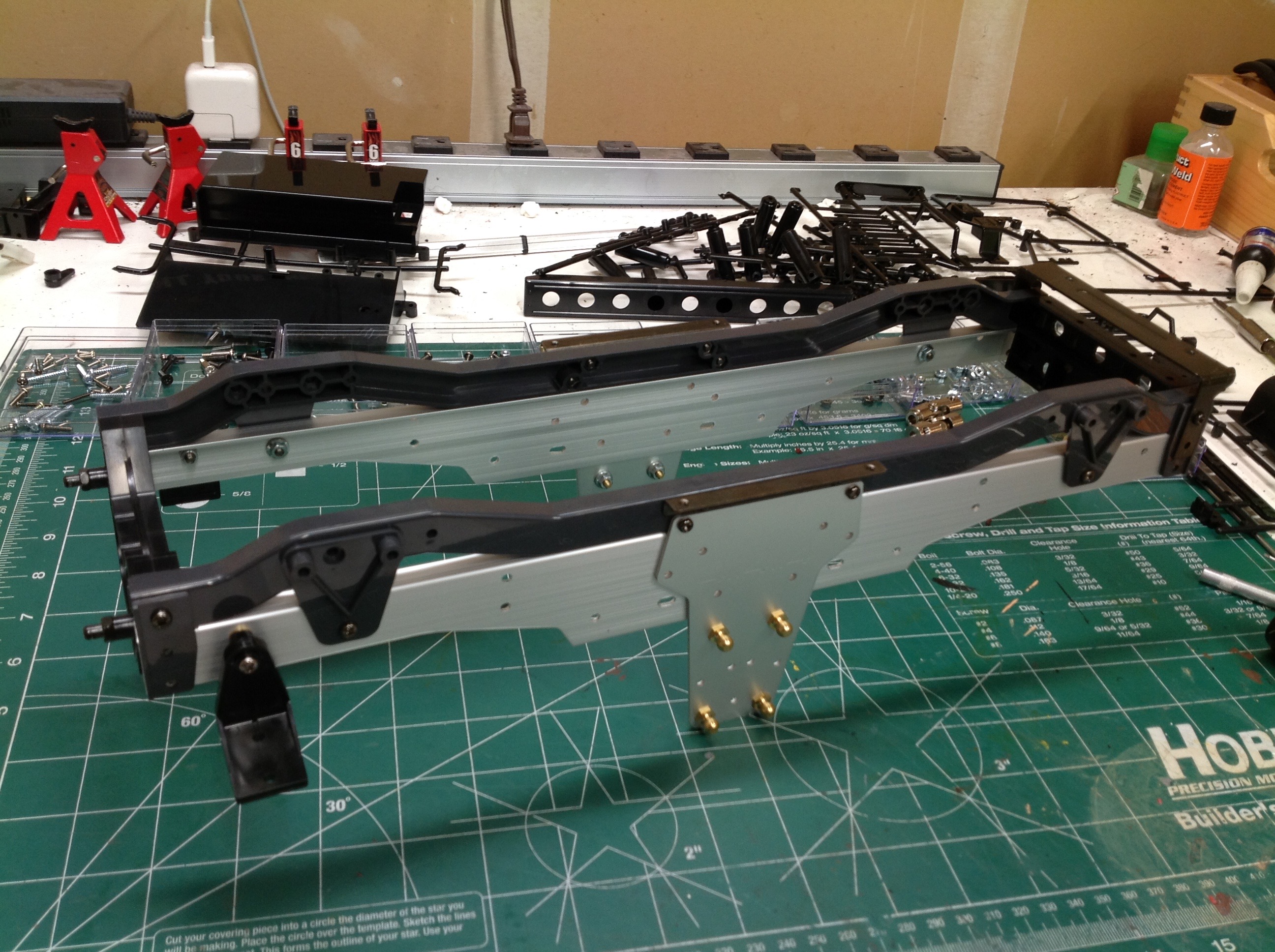
We can now connect the left and right chassis rails with a front and
rear plastic cross member. The majority of the lateral strength
actually comes from the lift actuator and the gearbox though. On
the right you can see the lift actuator installed between the chassis
rails, and you can see how far down the rack gears protrude. The
slot in the rear cross member is where the battery will go.
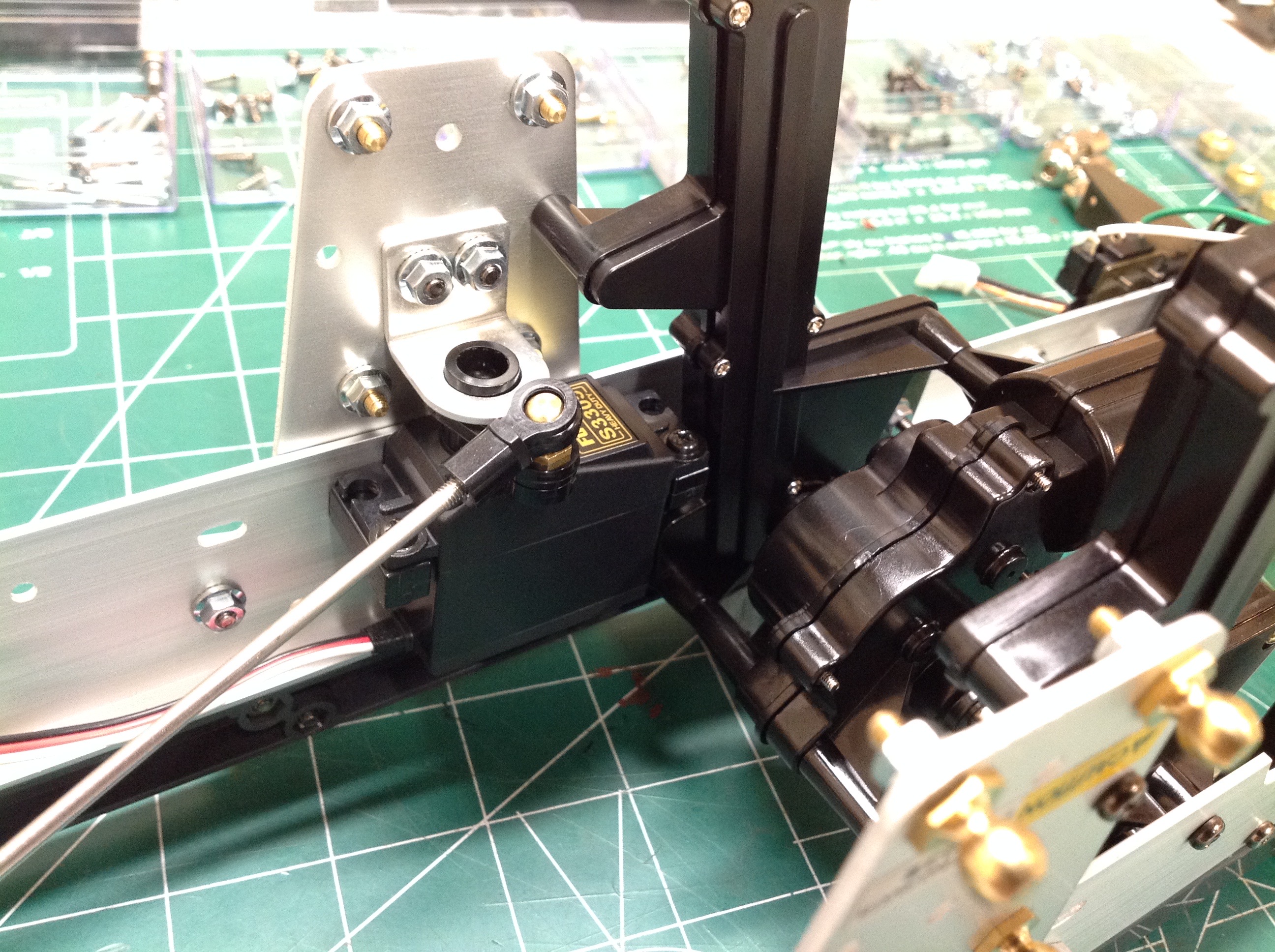
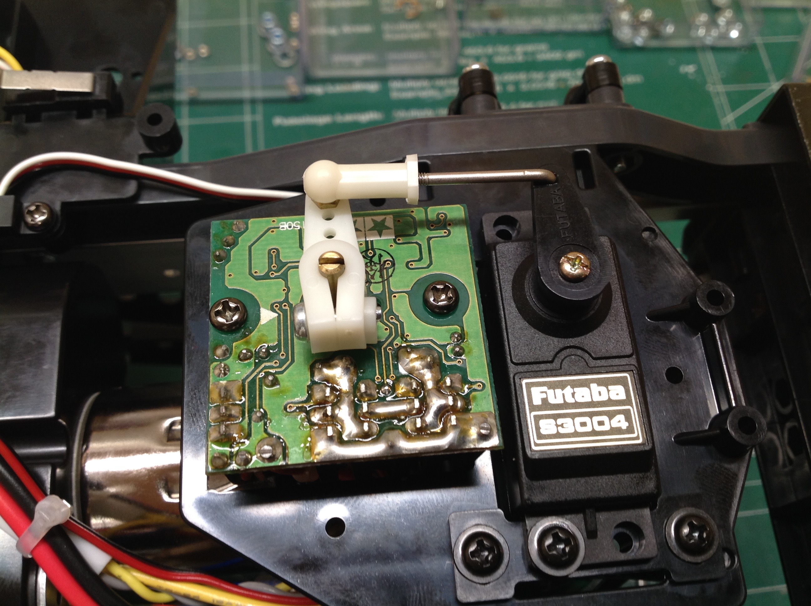
The steering servo is chassis mounted and faces down as shown. I
chose a Futaba metal gear servo with a torque of about 125 in-oz.
This is not a huge torque compared with a crawler servo, but I'm not
going to be doing heavy off roading with this vehicle. Note the
metal bracket which helps support the servo output horn. On the
right you can see how the gearbox rigidly ties the left and right
chassis rails together.
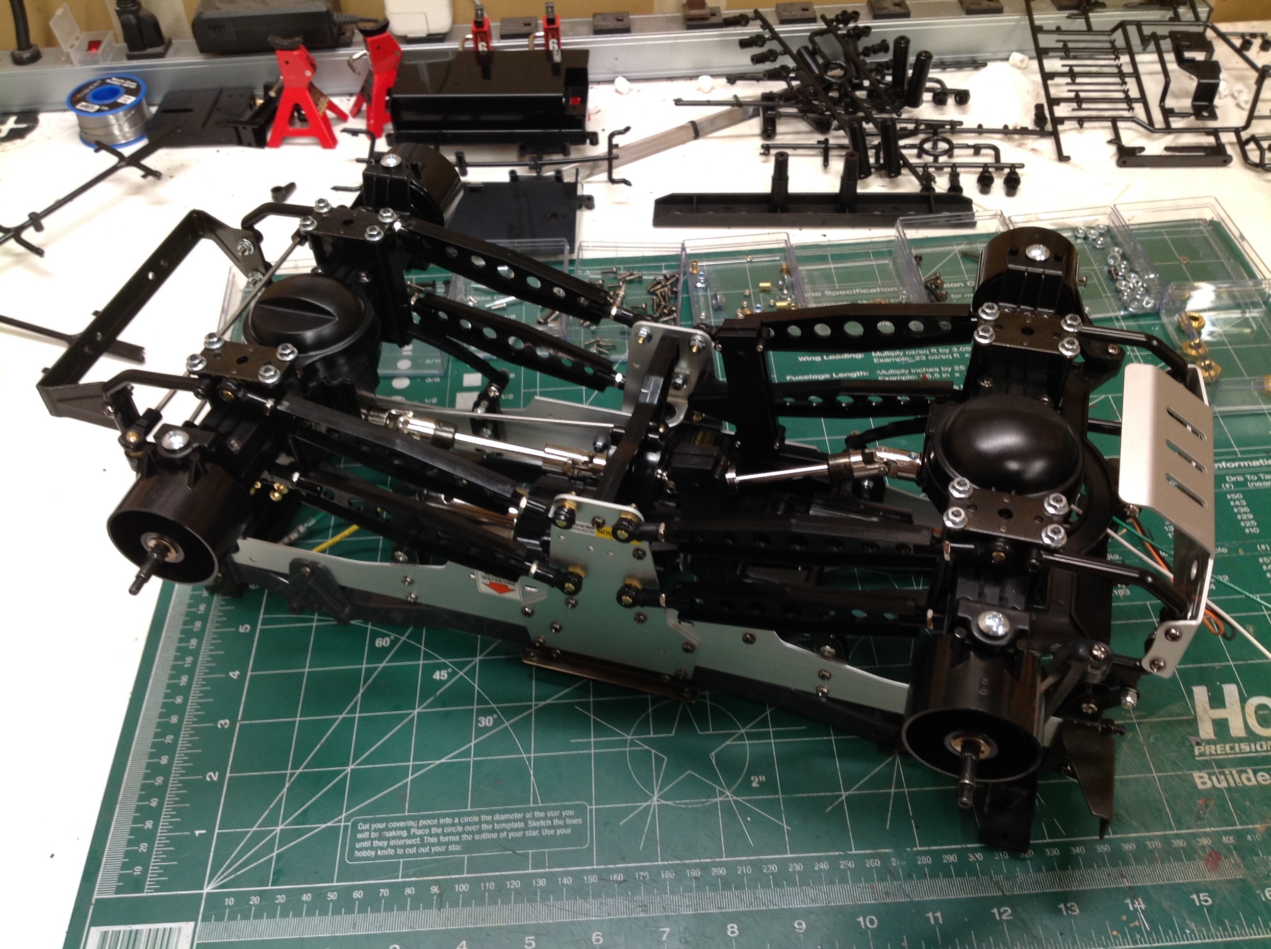
We can finally install those huge axles to the chassis using the 8
identical links we made earlier. Installation consists simply of
popping on the 16 ball joints and attaching the drive shafts.
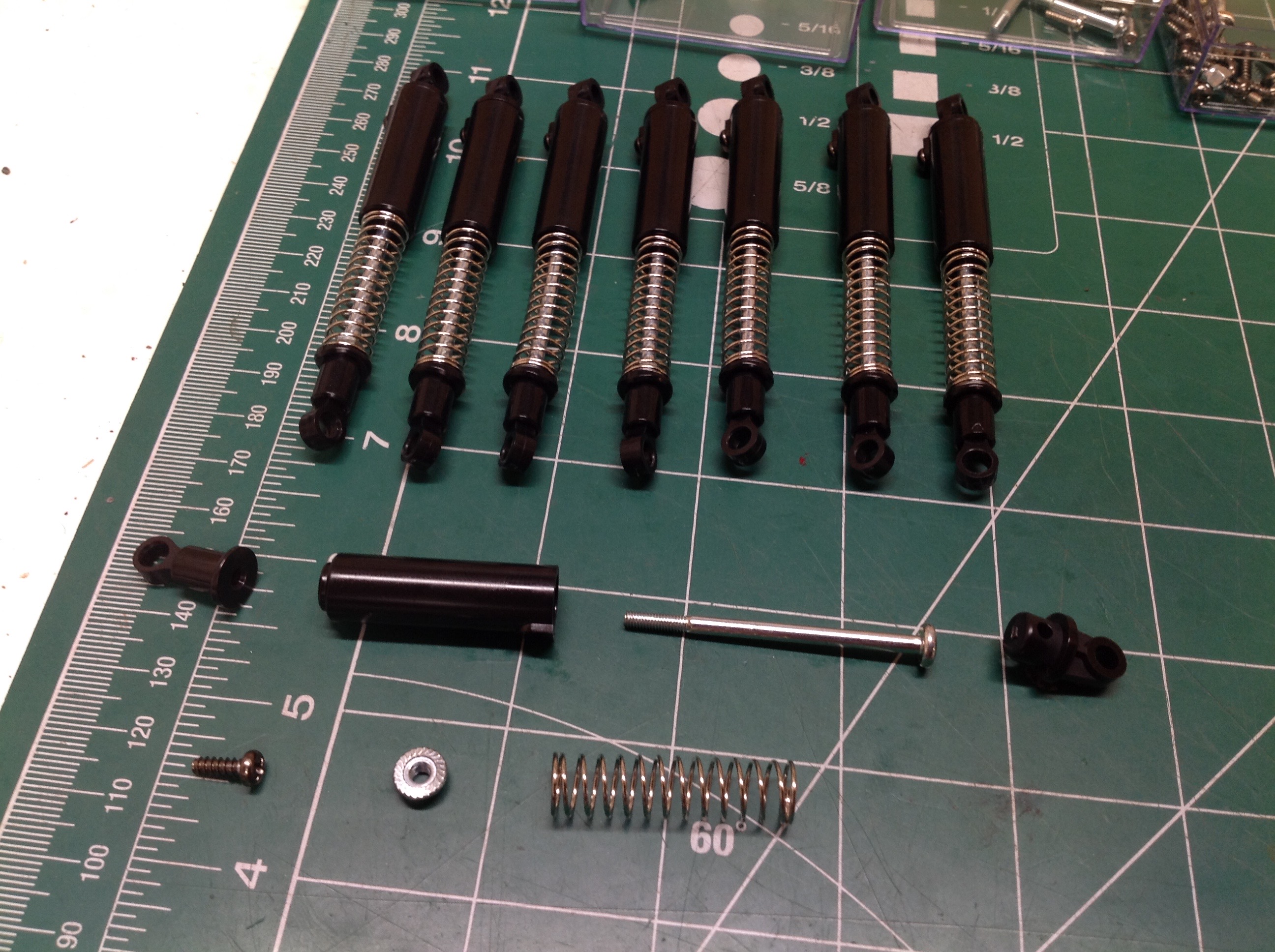
This model uses 8 shocks. These are friction dampers with no oil,
and in fact they don't really have any friction either. As it
turns out, the suspension is so stiff that it barely moves so the level
of damping is irrelevant. At least they look pretty good.
Golden oil dampers were available as a hopup, but are worth their weight
in real gold now so I don't have any.
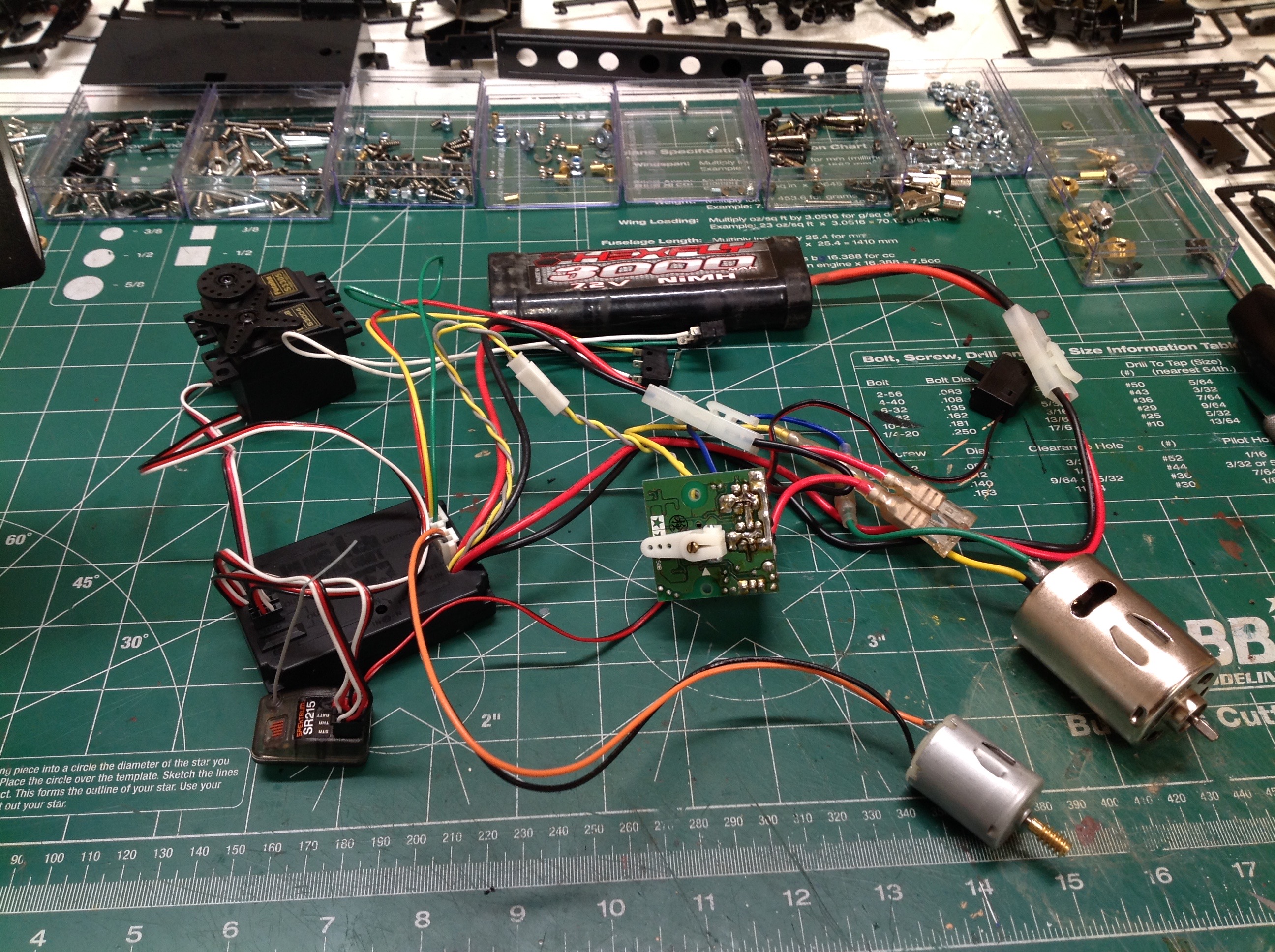
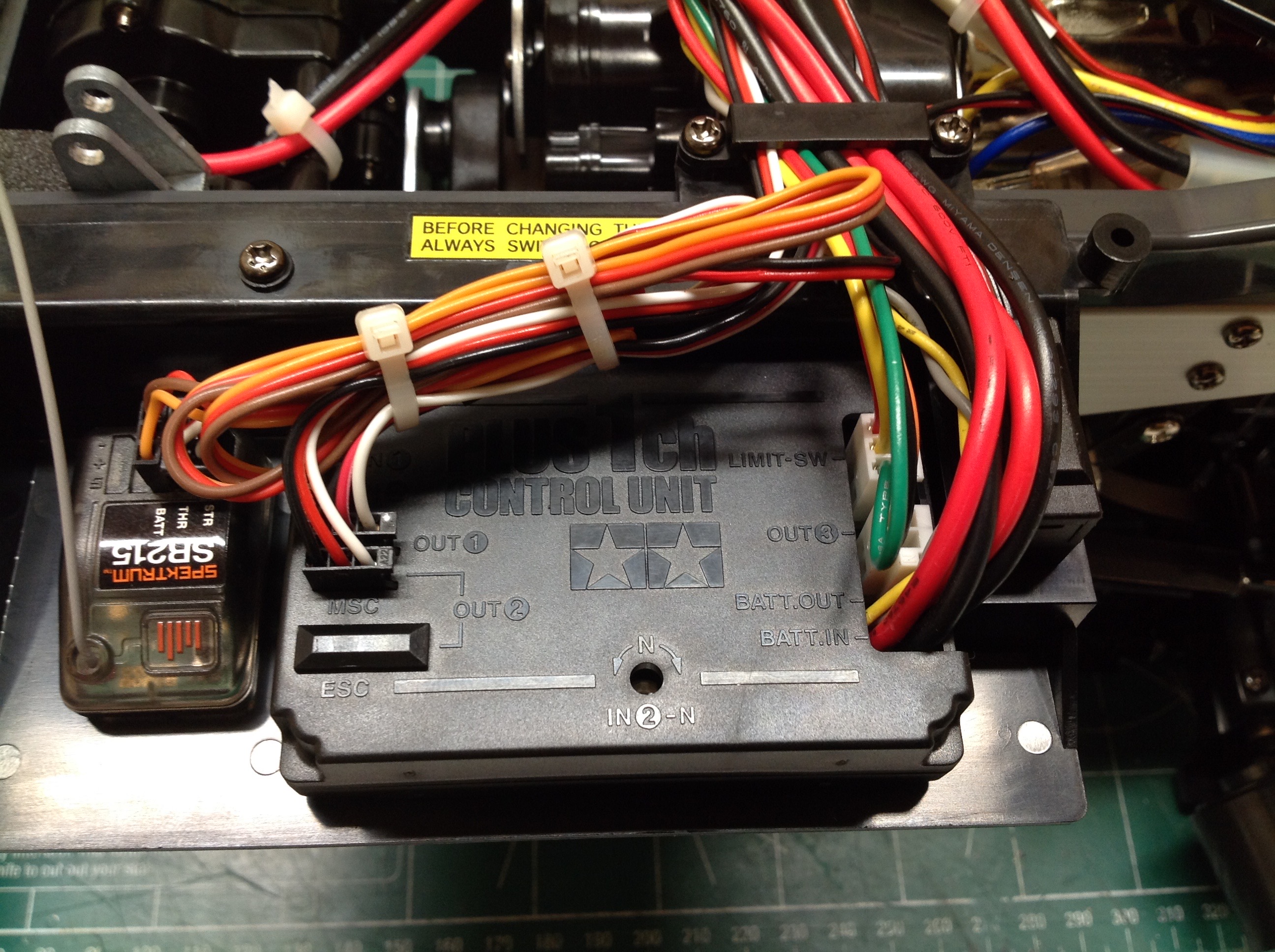
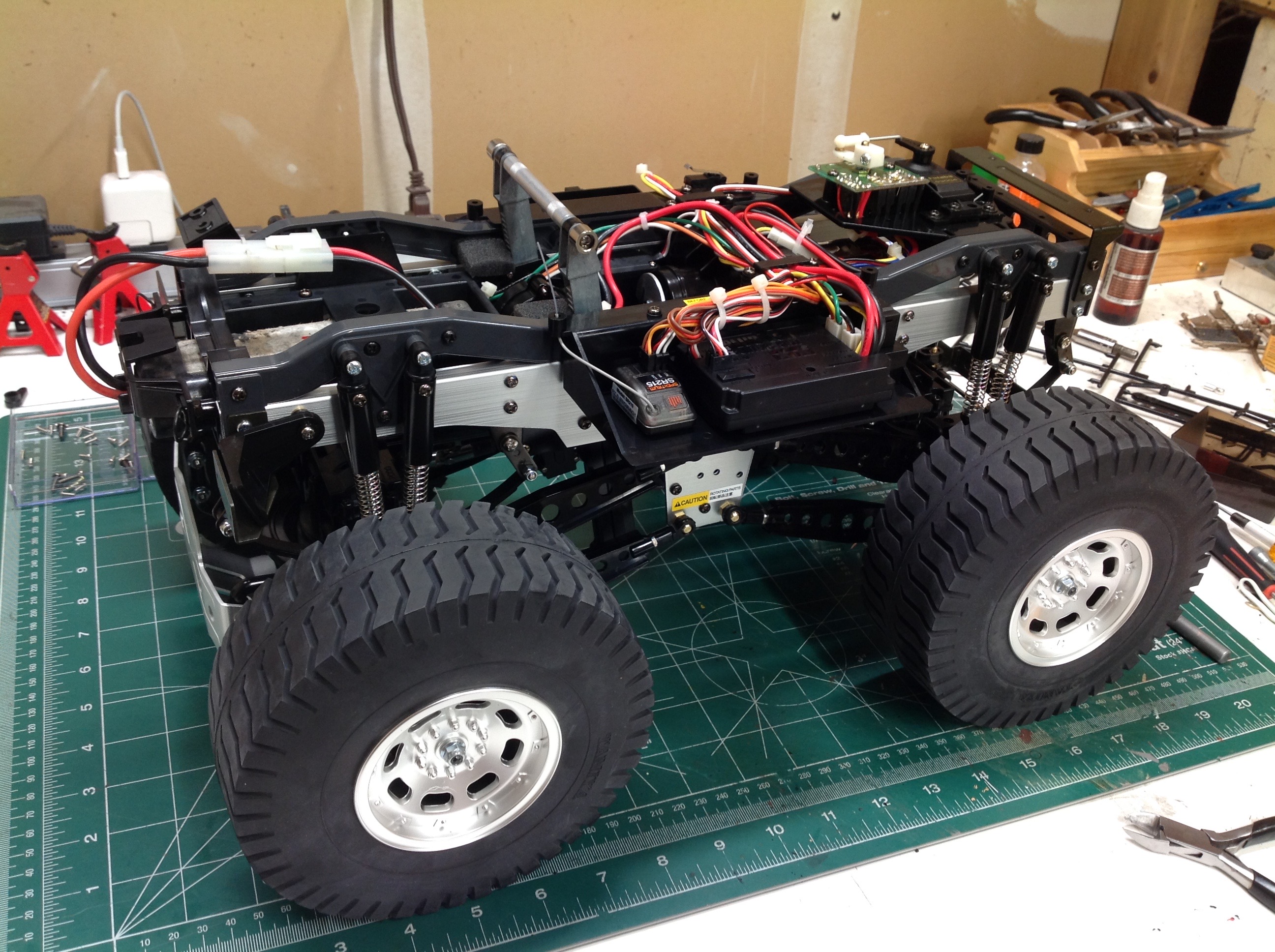
Wiring a 2-channel RC is usually a pretty trivial matter, but not so
here. We have servos for both steering and throttle because of the
Mechatronic Speed Control. The MSC uses a servo for input, but it
is not mechanical. It has an actual FET and proportional control
with a built-in BEC and no external resistor. This means the
battery power has to pass through the MSC before going to the radio and
to the main motor. But that's not all, we also have the Plus 1ch
Control Unit which drives the lift actuator without an additional
channel. This unit is commanded by holding full left or right
steering for more than 1 second, but only when stopped (no
throttle). It therefore needs power input, power output, and
pass-through for both radio channels. It also uses a pair of limit
switches to shut off the lift actuator at full up and full down to
prevent stalling the lift motor. Add all of this together, and you
get the huge mess of wires shown. I had originally planned to
replace the whole system with a modern ESC and put the lift actuator on a
3rd channel, but the system works well and is part of the charm of this
historic model so I have left it stock.
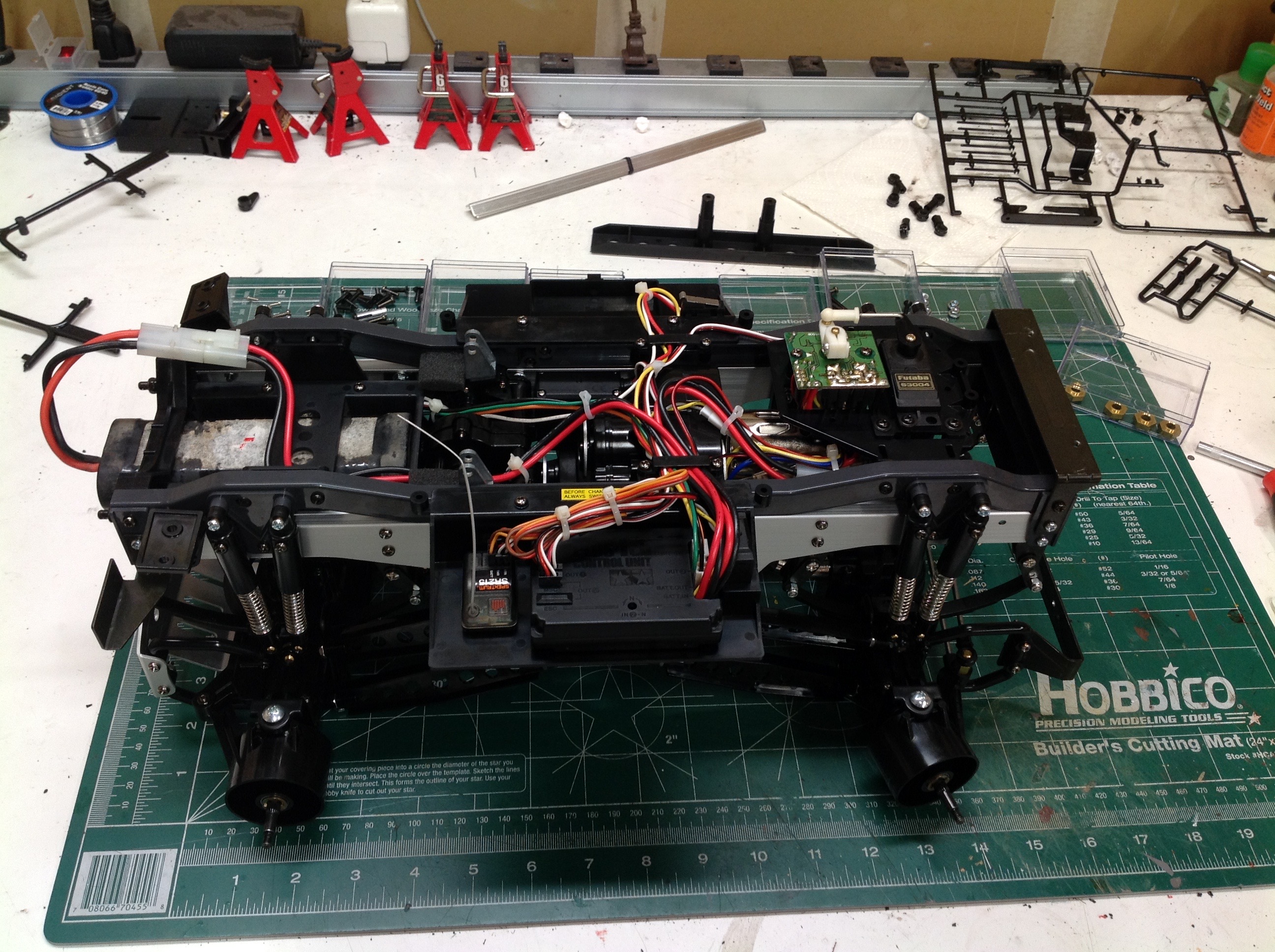
The model includes a good system for routing and restraining the wires
and making them reasonably neat. This is pretty important because
there are some big moving parts in back that could destroy the wiring if
it was not carefully protected. The modern receiver on the far
left looks out of place for being so tiny. The Mechatronic Speed
Control shown on the right is a convoluted idea if ever there was
one. First we use a potentiometer on the transmitter to convert a
rotation to a signal. Then we sent that signal to a receiver which
outputs to a throttle servo. That throttle servo uses another pot
to detect its own output position. Then, finally, the MSC takes
the servo output through another pot to command motor output. A
modern system eliminates two of these steps.
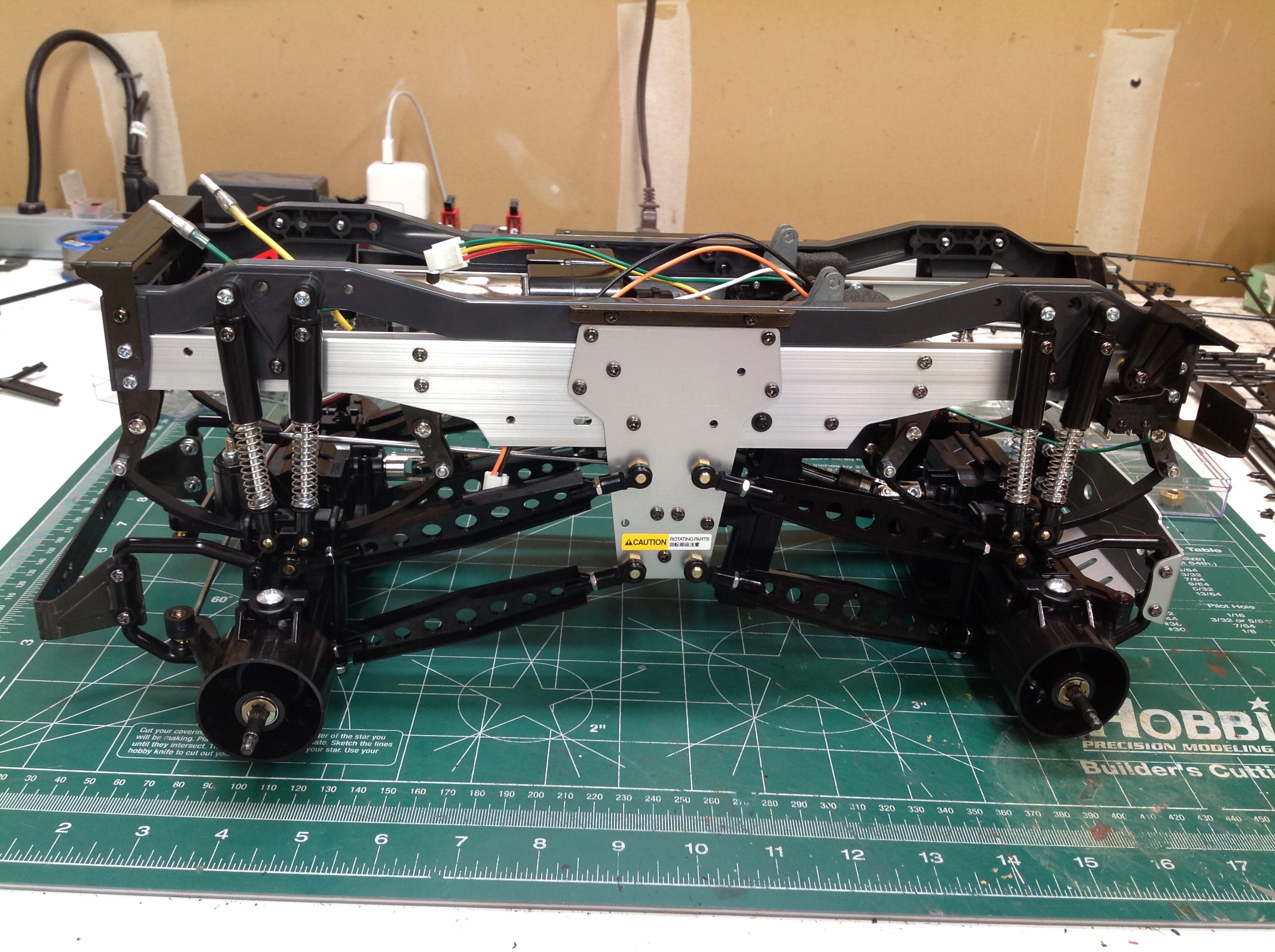
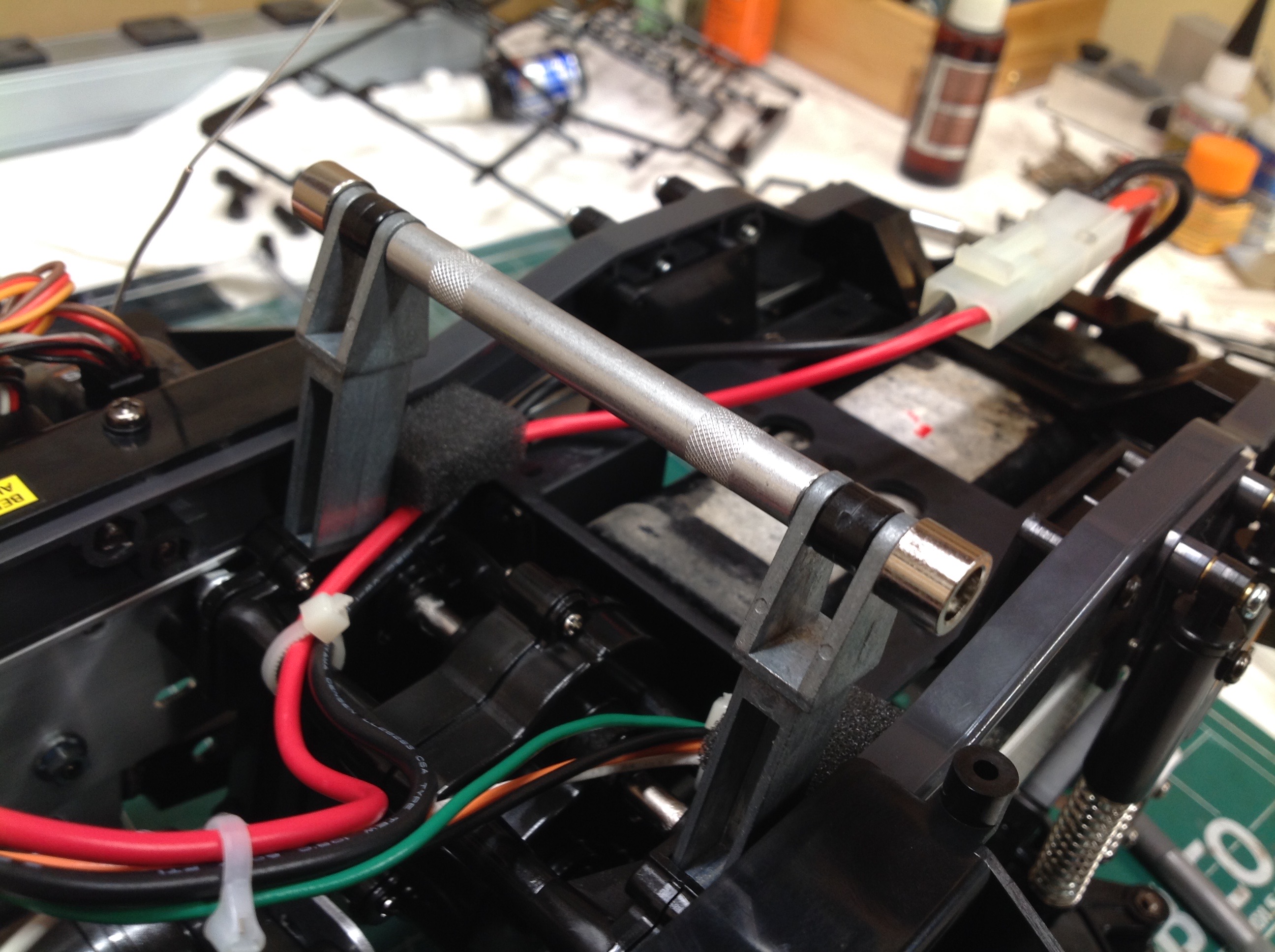
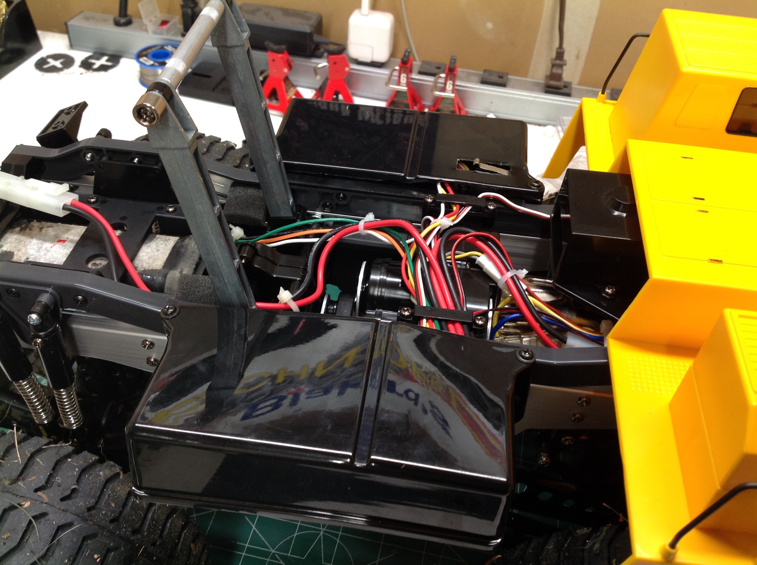
Here you can see the wiring path back to the battery. The cross
bar between the lift racks is what will lock into the bed once it is
installed. On the right you can see the polycarbonate tubs which
cover the electronics pods.
The rolling chassis is completed by installing the huge wheels and tires
which are unique to this model. A real haul truck would have dual
rear wheels, but that wouldn't be possible on the model without
significantly narrowing the rear axle. This chassis is one heavy
beast, but even so there is virtually no suspension compression driving
off road. This makes sense since the suspension would be sized
based on carrying a full heavy load in the bed.
©2019 Eric Albrecht