Proline Pro MT 4x4 Project
Page 3: Rebuild
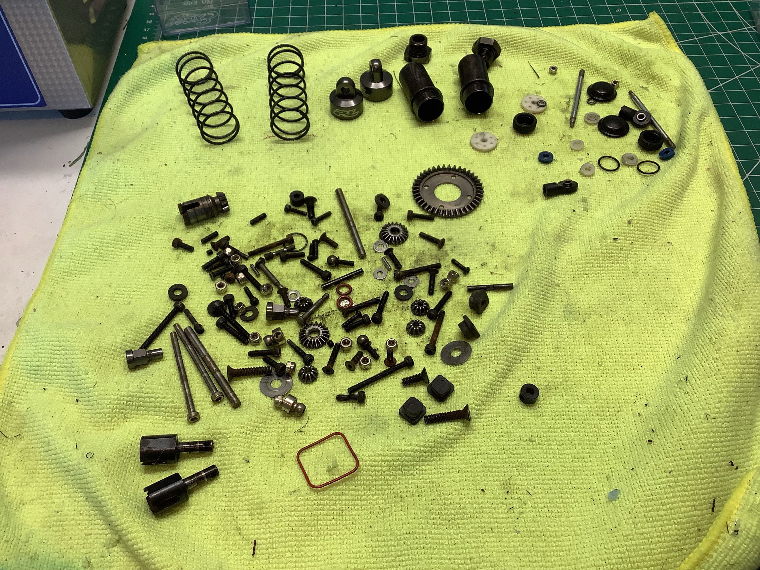
This picture shows all of the hardware I removed from the first part of
the model when I did the teardown and rebuild. I did the project
in modules starting with the rear suspension which is what you see
here. I washed everything in the ultrasonic cleaner before
re-assembly.
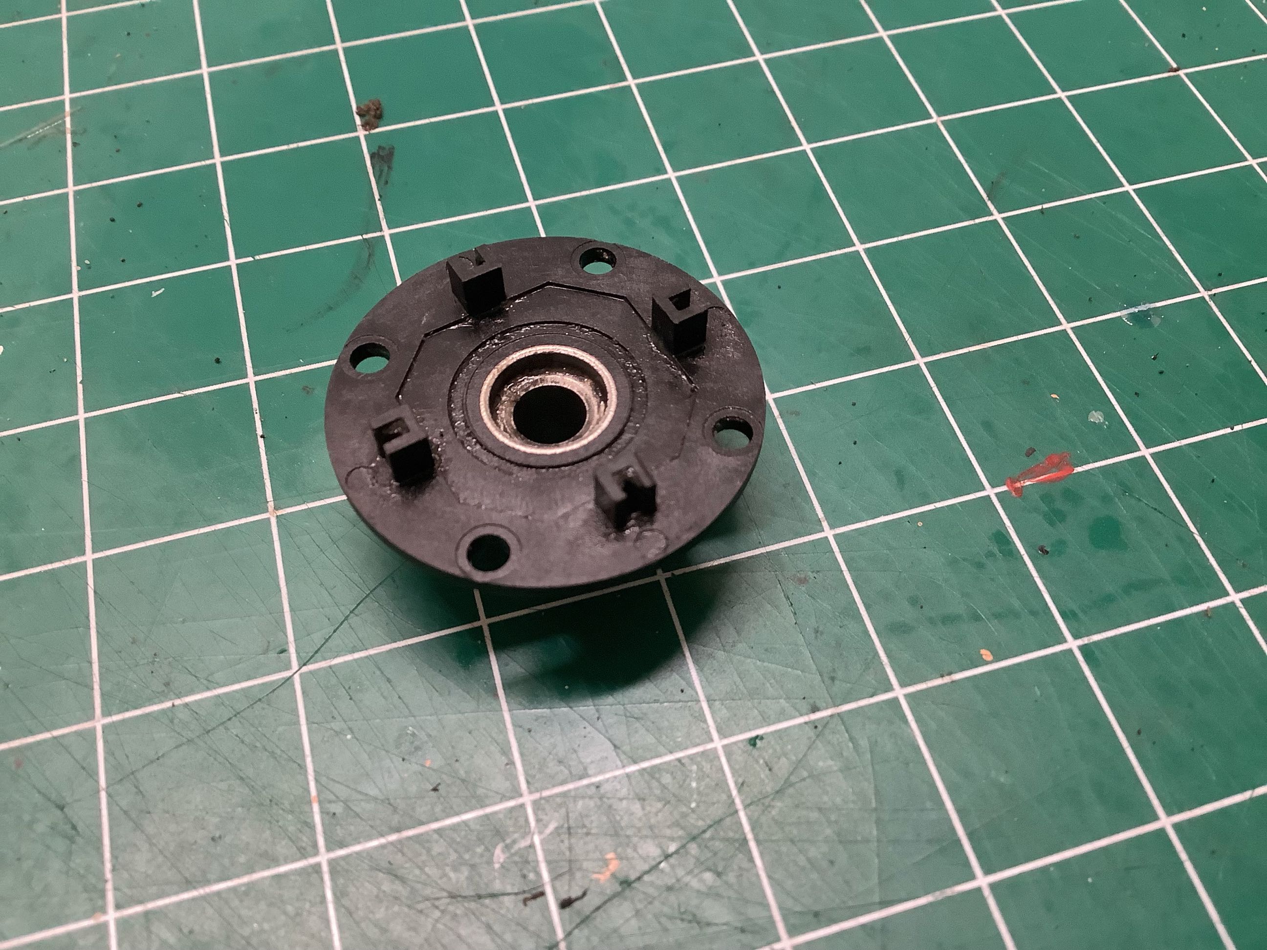
Here I'm rebuilding the rear differential. The metal part shown on
the left is pressed into the plastic and can't be removed. This
serves as a sliding surface bearing for the inner side of the drive
cup. A roller bearing is used on the larger diameter outer
edge. There is an o-ring below the washer on the right making this
a sealed differential, but the front and rear builds only use grease
rather than fluid.
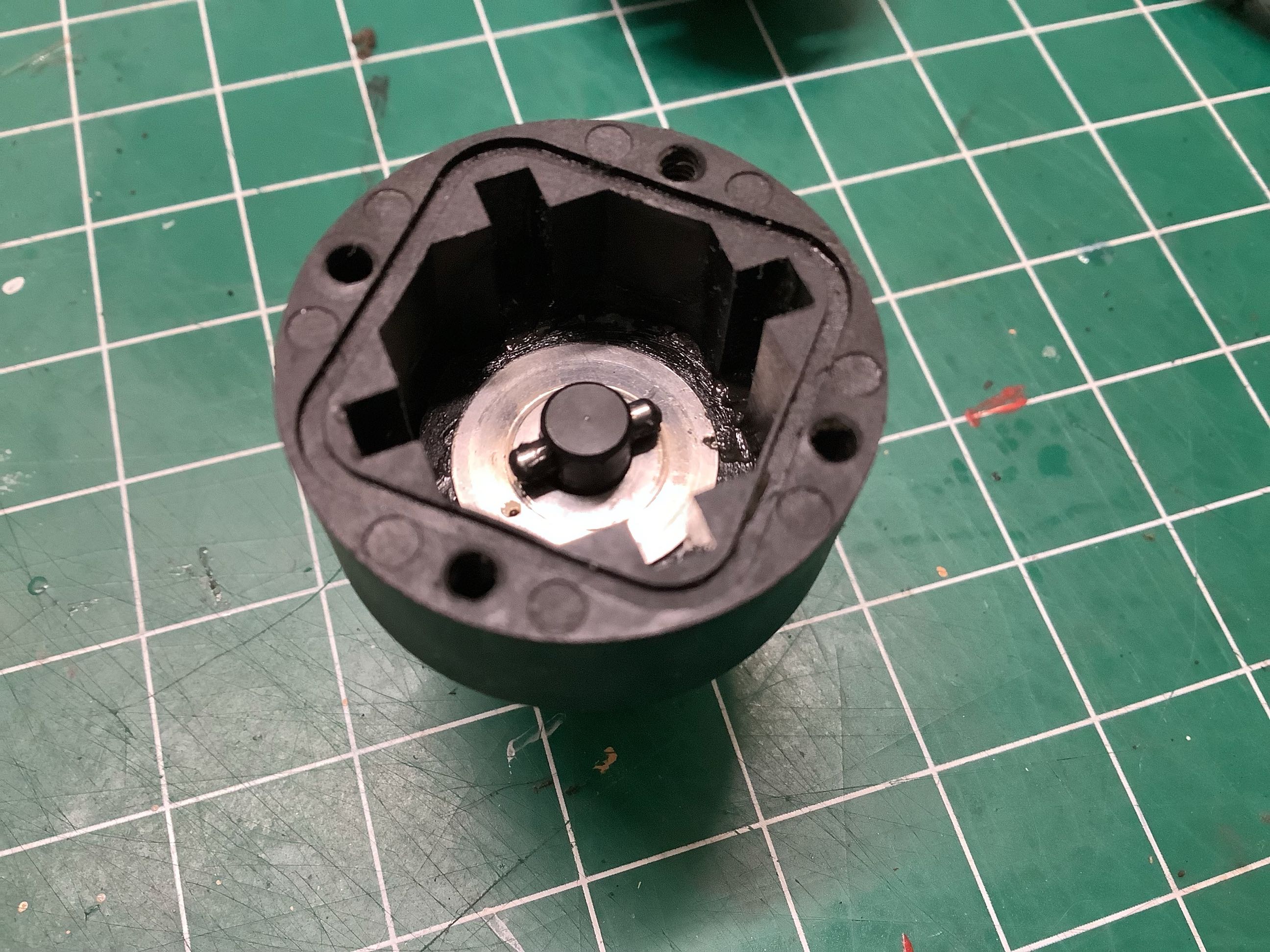
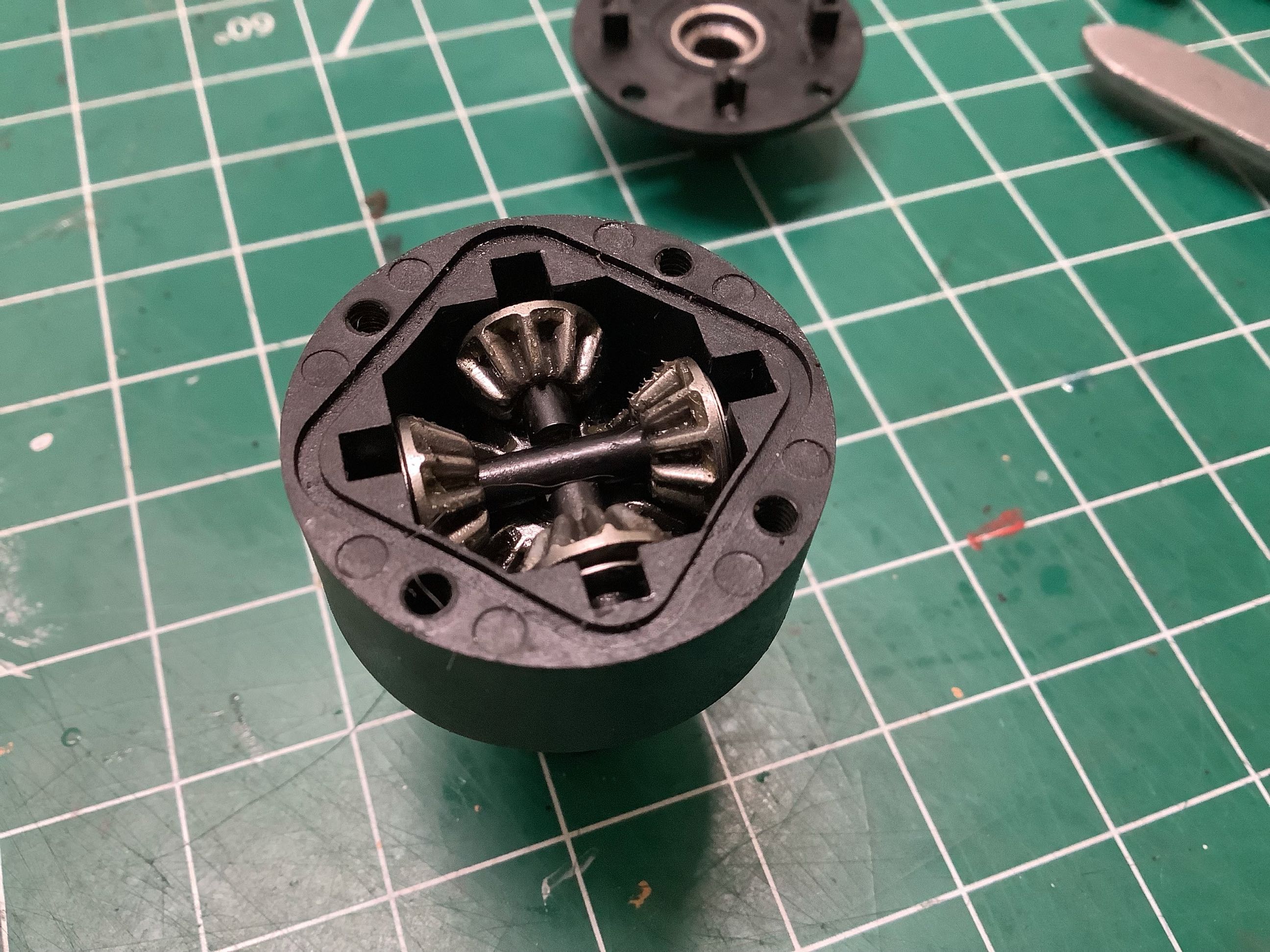
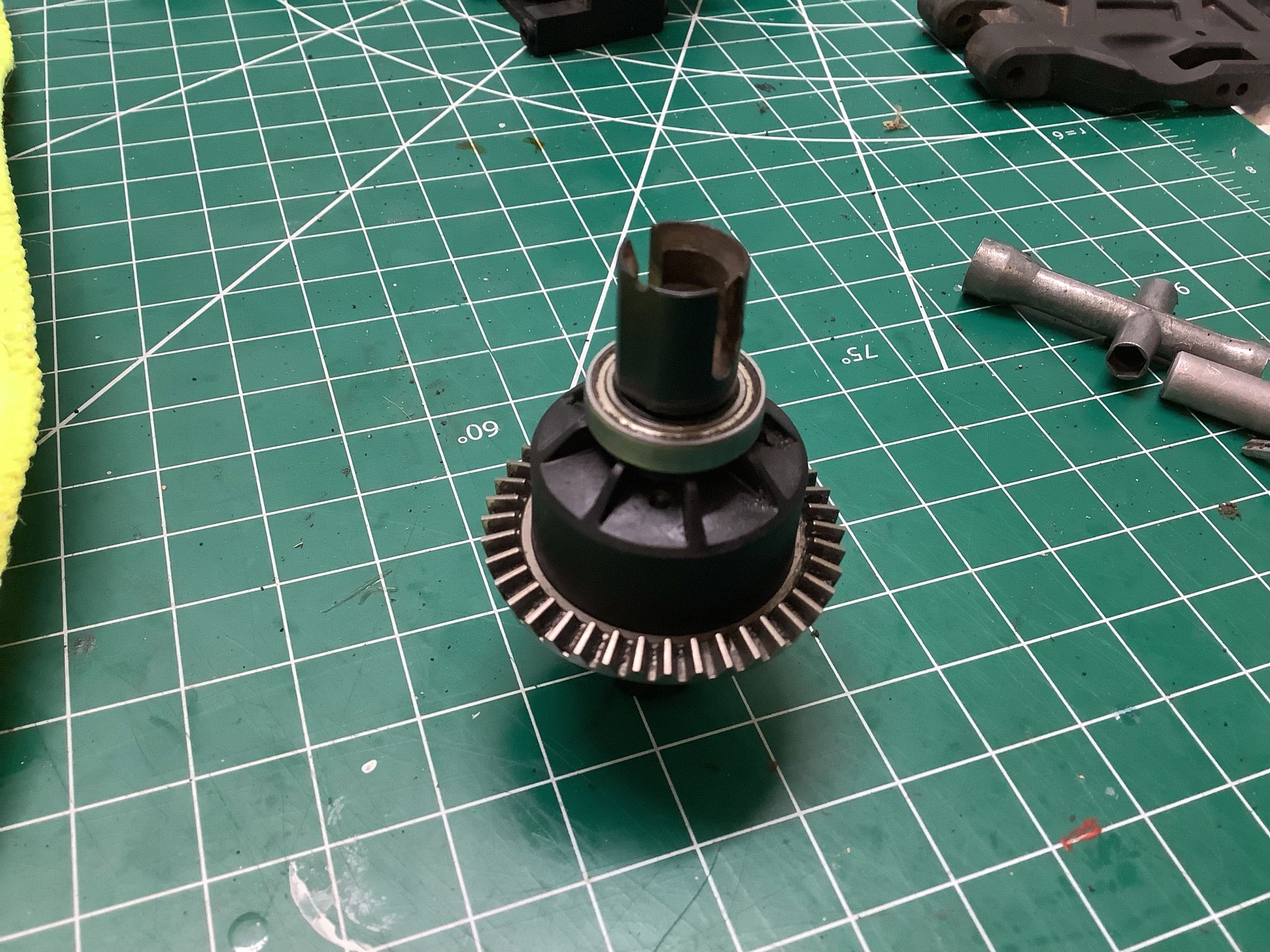
The left hand picture shows the 4 steel differential spider gears.
You can also see the rectangular slot for the seal. On the right
the differential has been completed by adding the ring gear, the drive
cups, and the outer bearings.
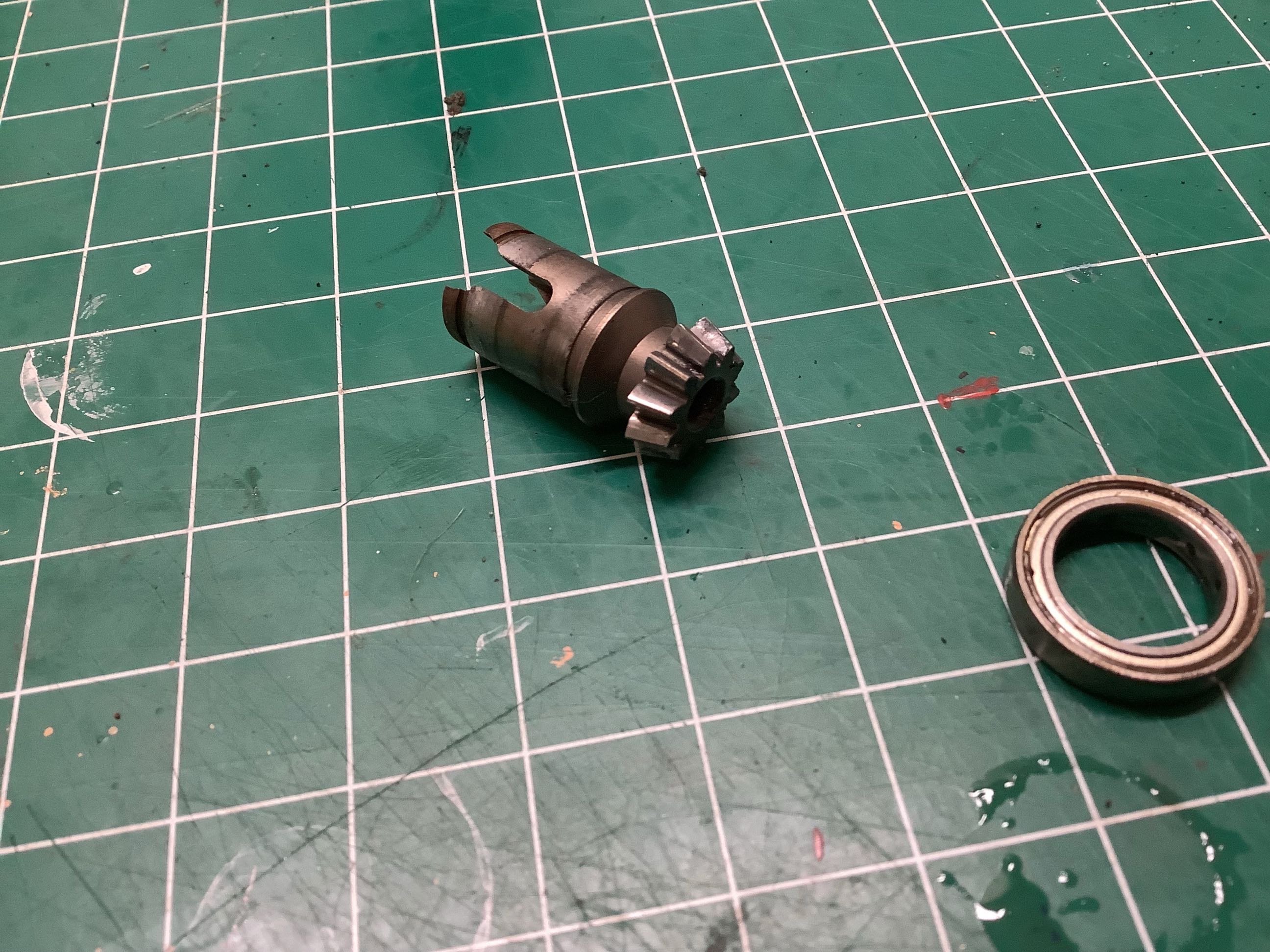
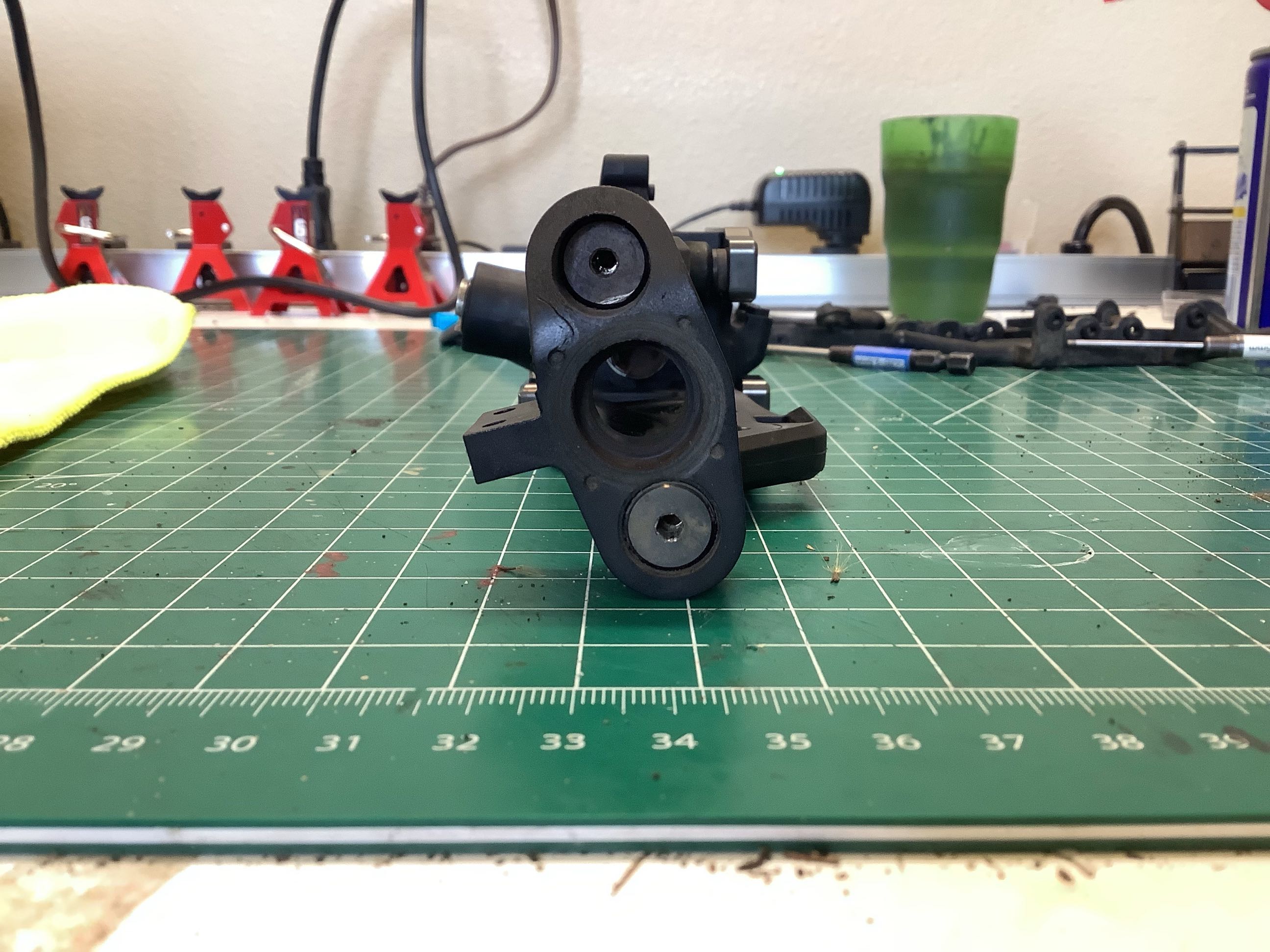
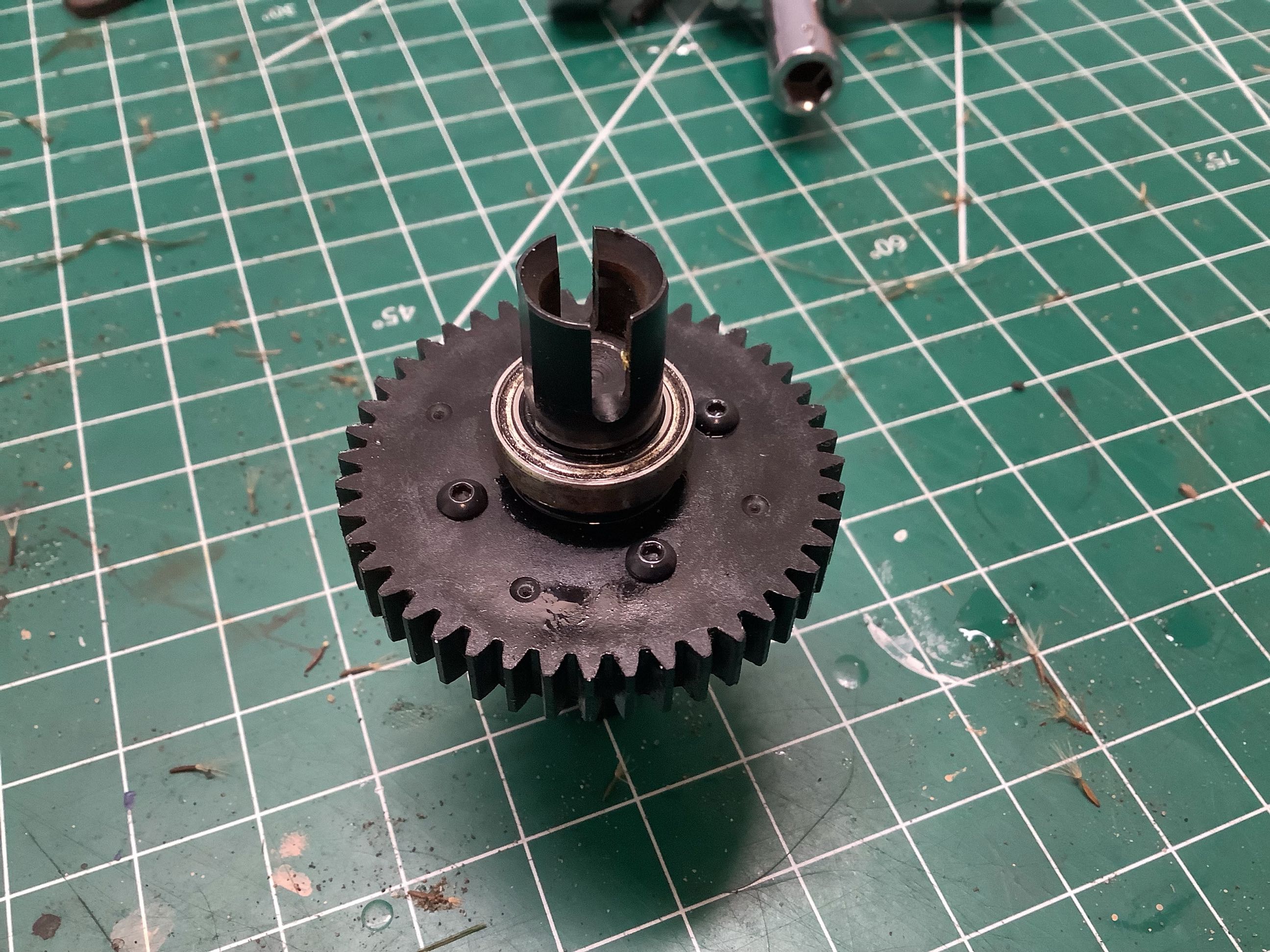
The pinion gear for the differential is integrated into the center drive
cup and is supported by a pair of very large 18x12 bearings as shown on
the right A snap ring retains the pinion without the
housing. This system can't really be shimmed.
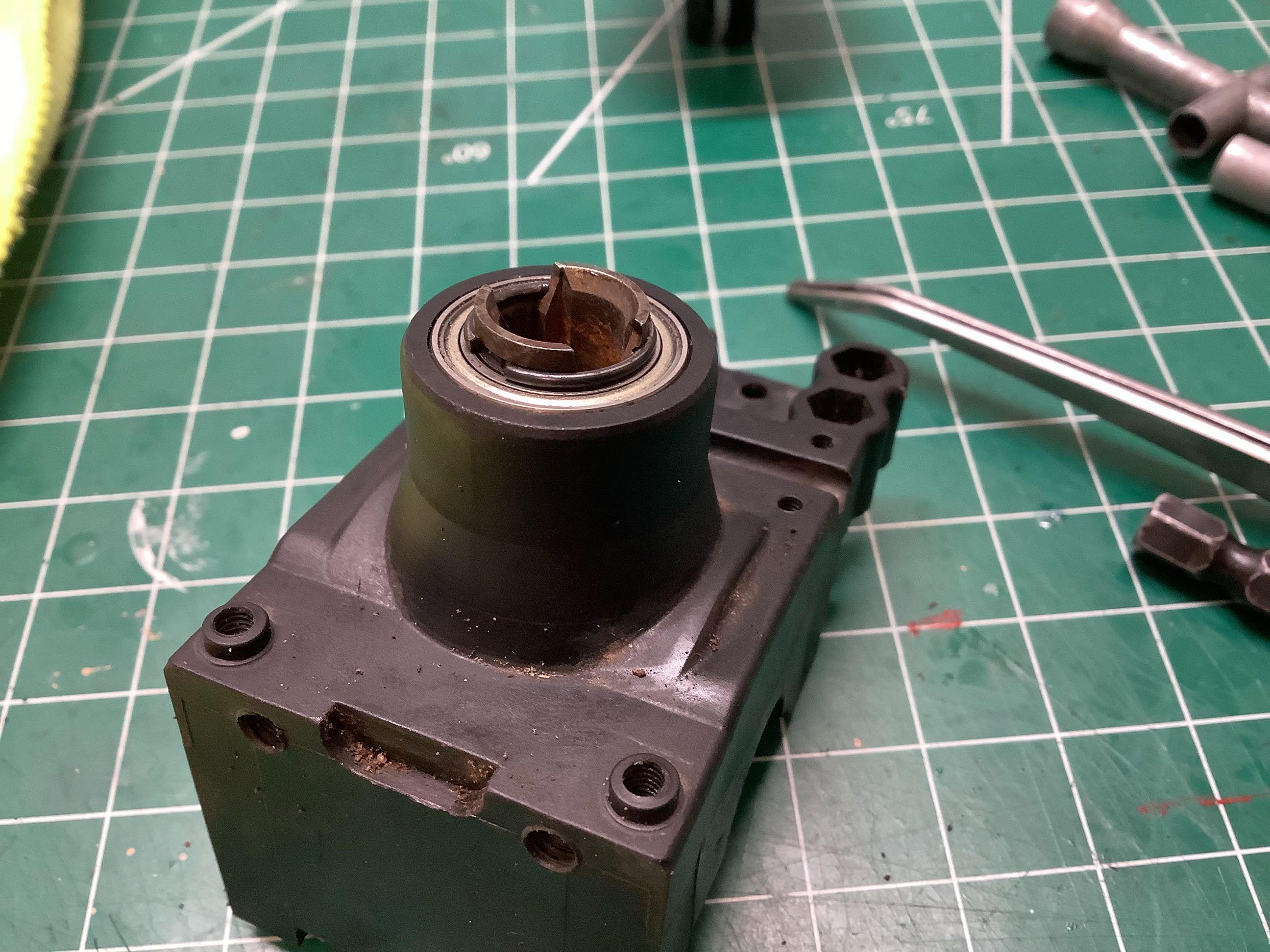
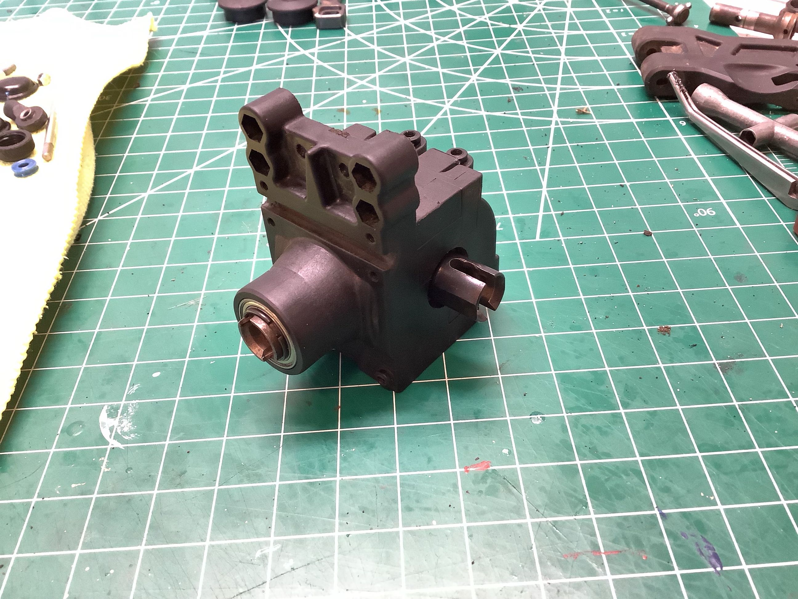
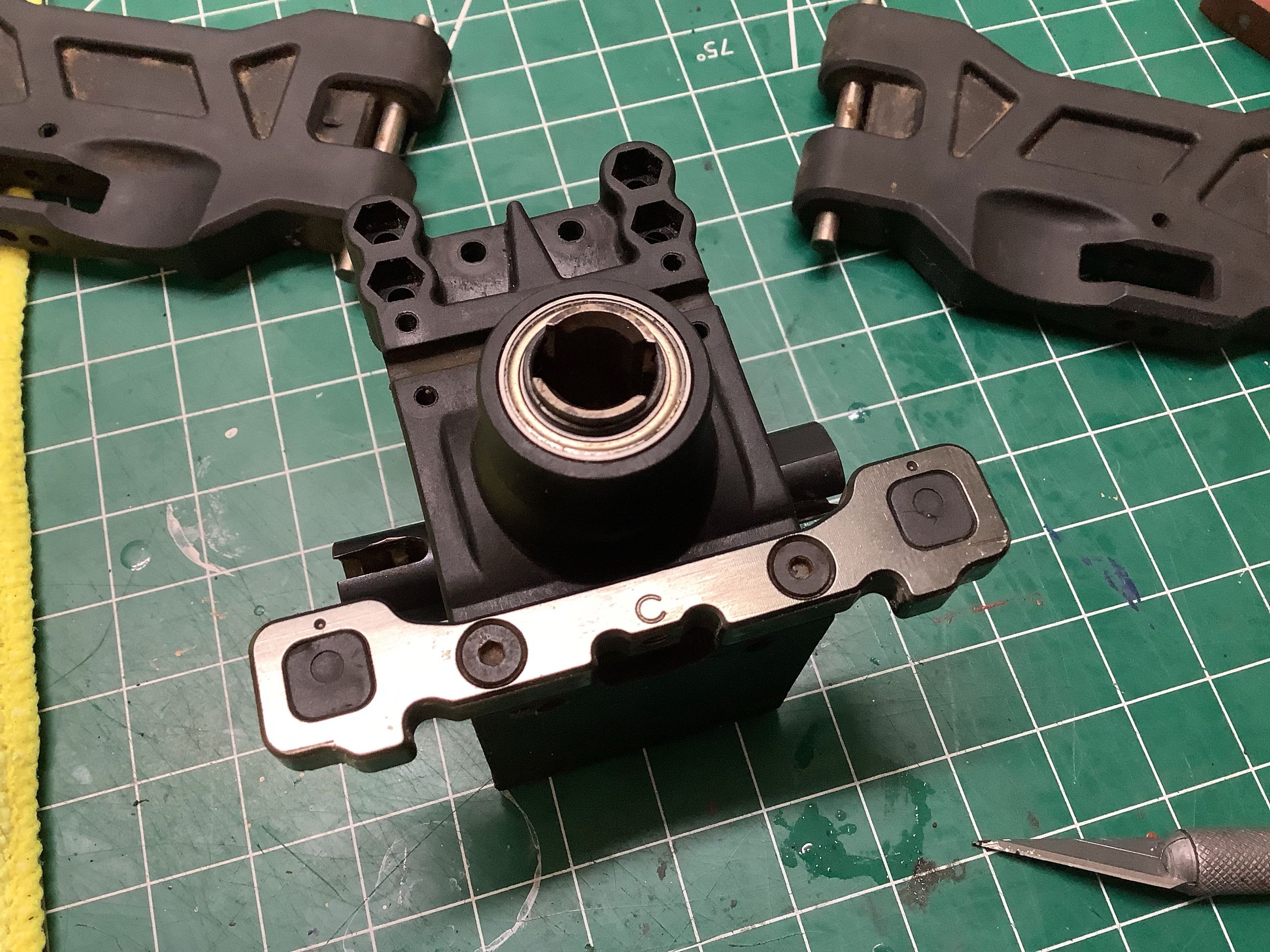
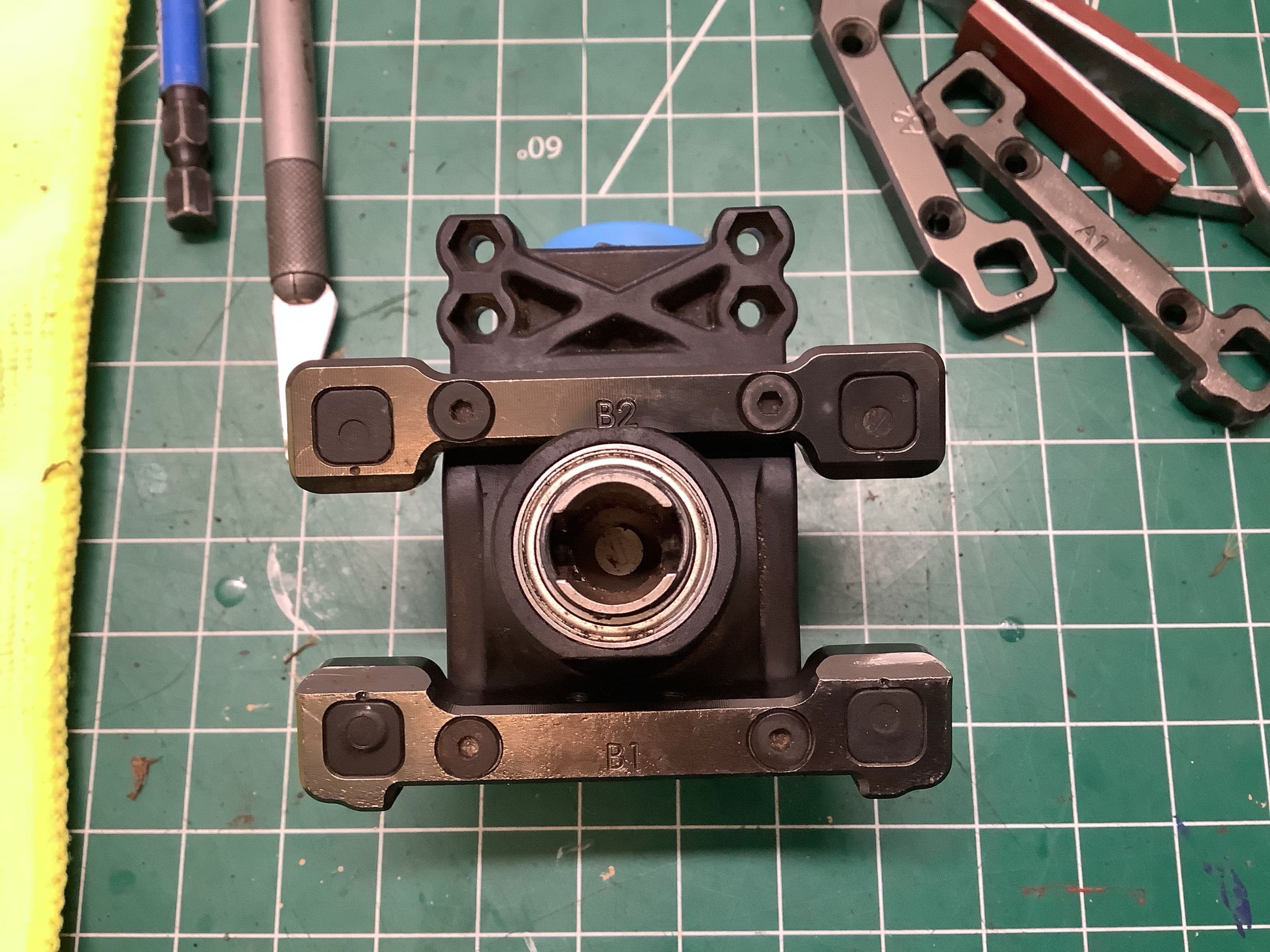
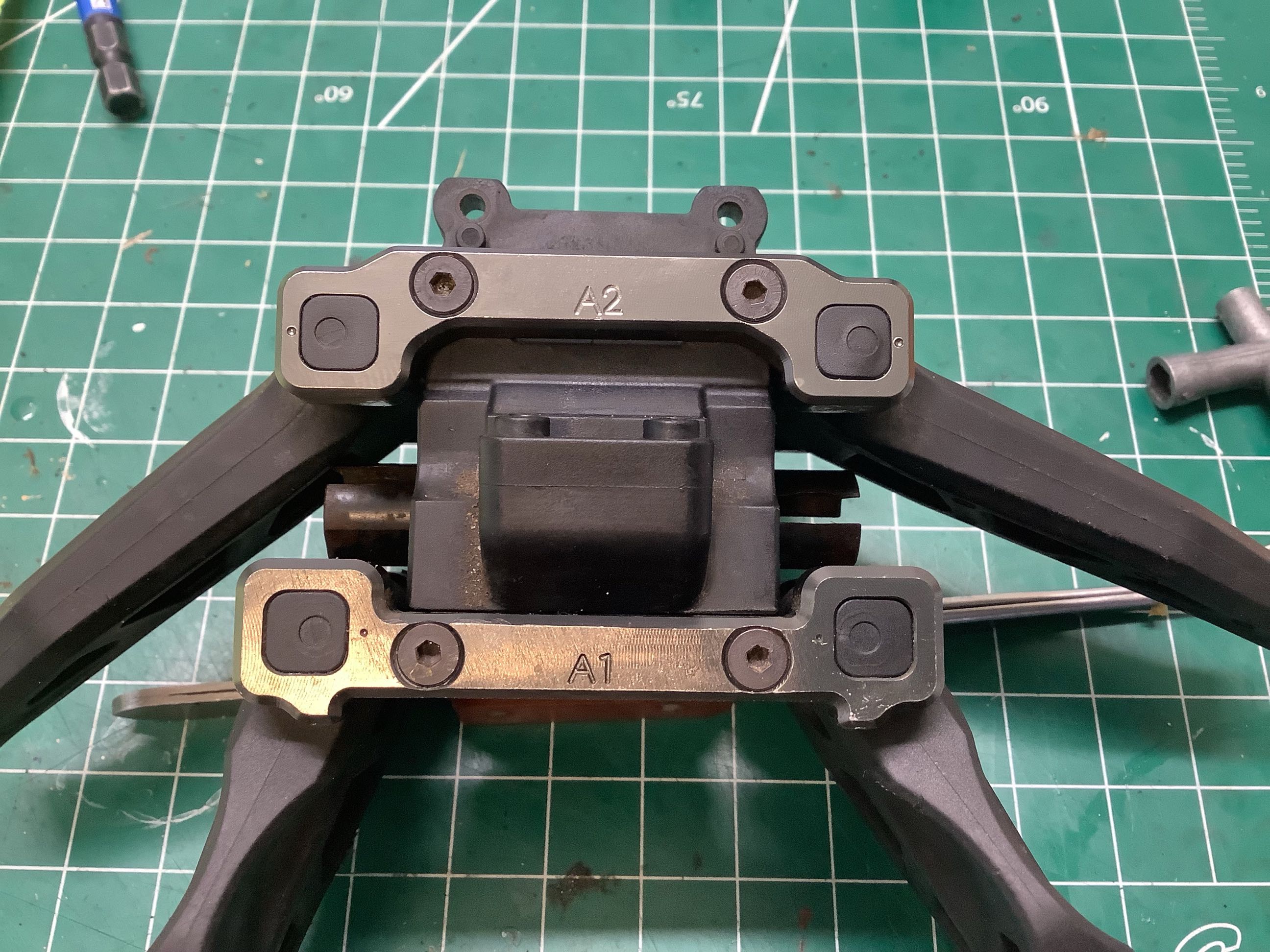
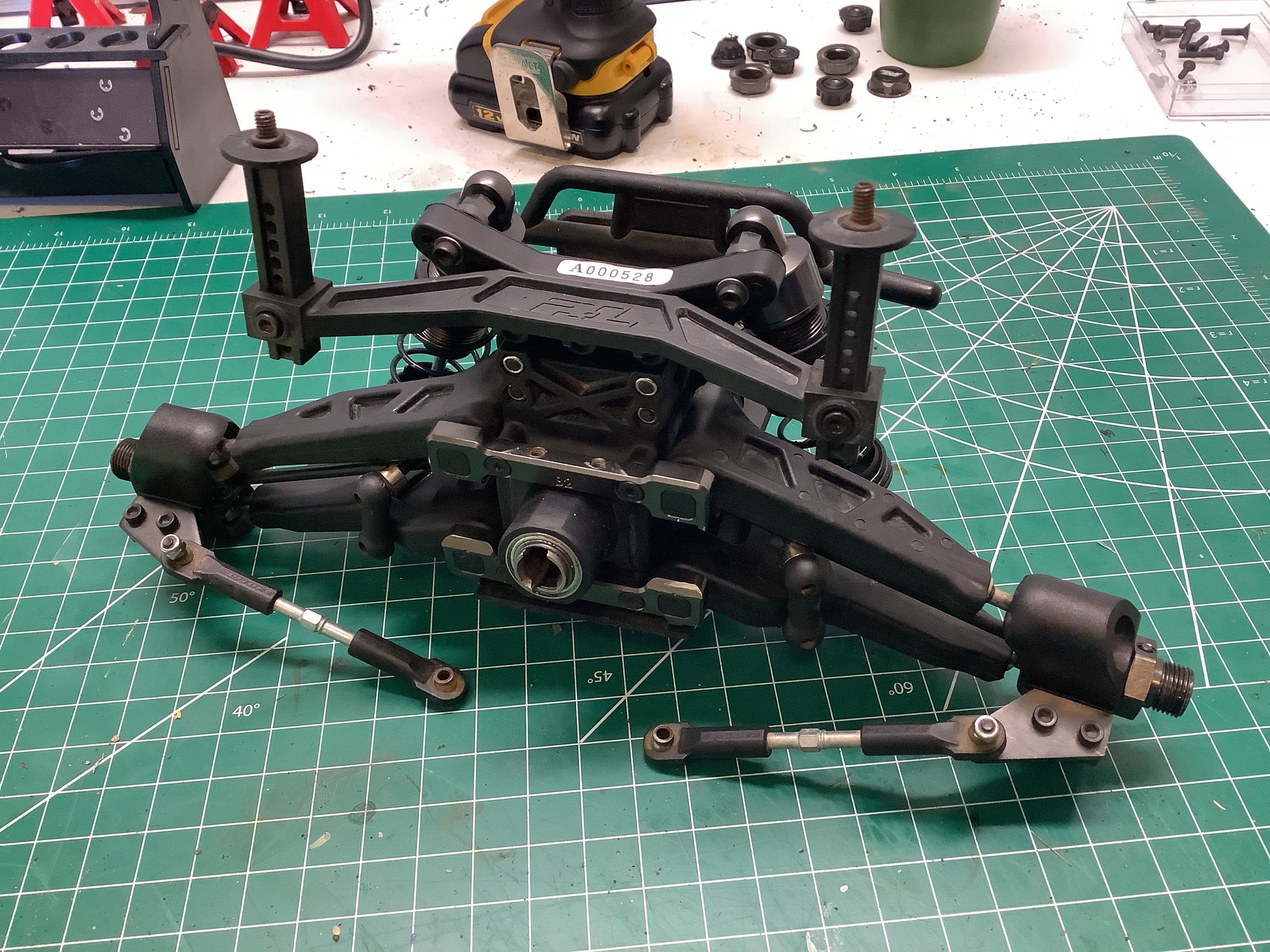
Here the differential has been fully installed into the housing.
The aluminum part marked "C" on the right supports the lower suspension
arms and simultaneously controls the rear toe and kick angle. If
you look closely you can see a dot on the square plastic inserts.
This dot is off center and indicates the position of the bore on the
opposite side. By rotating these parts to different orientations
and doing the same to the parts on the front edge of the housing, the
orientation of the lower suspension arm axis can be adjusted.
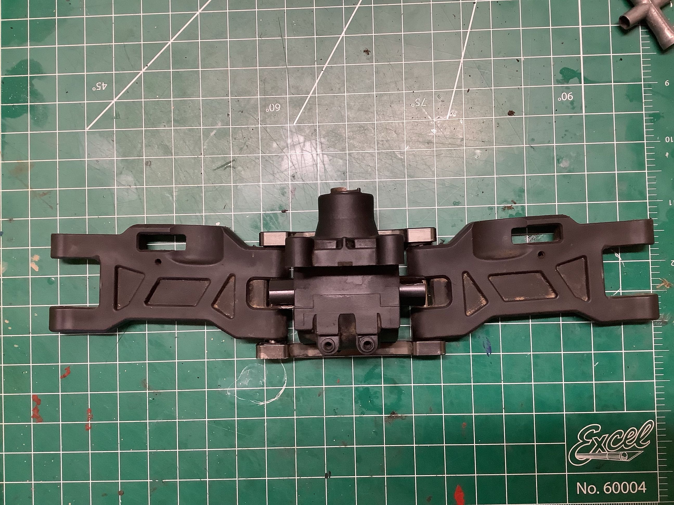
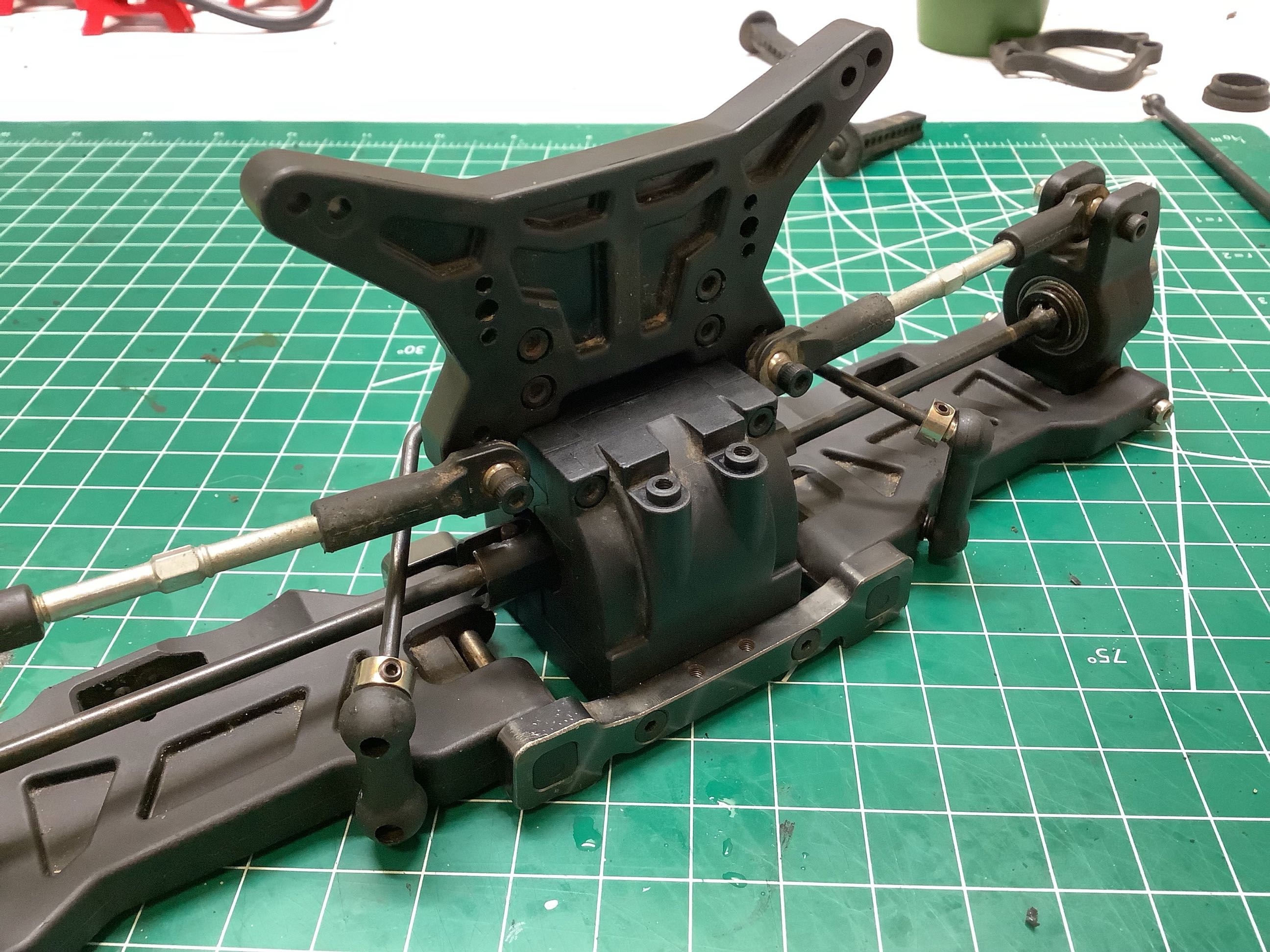
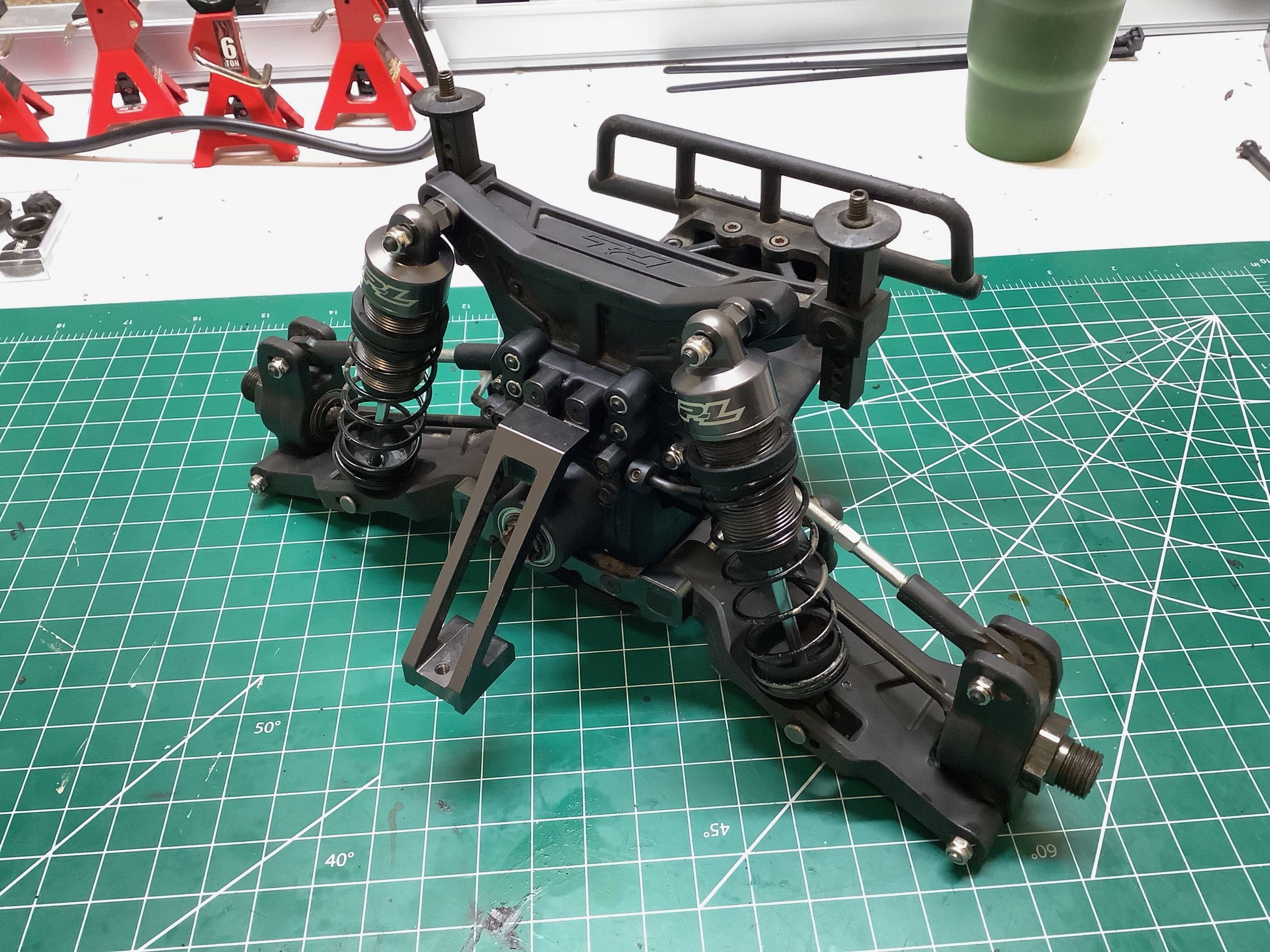
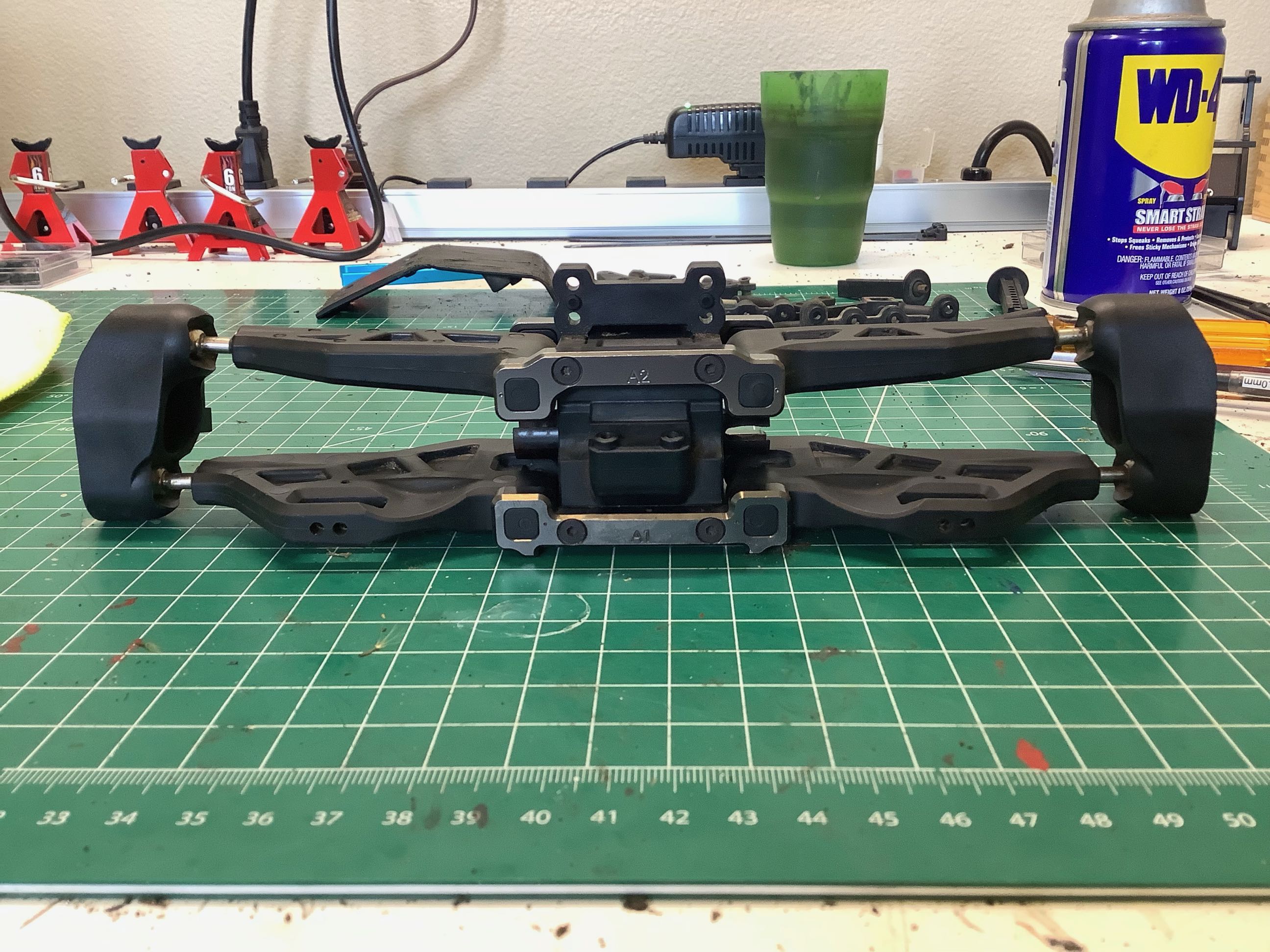
These photos show the installation of the lower rear suspension
arms. The aluminum parts which support the arms are very thick but
take a real beating if you hit anything with a tire. My rear
support was pretty bent but I was able to straighten it will a few
hammer blows. On the right you can see that I've also added the
shock tower.
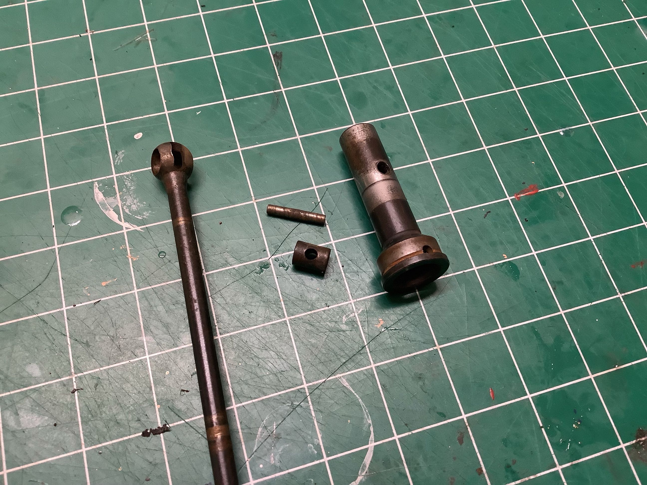
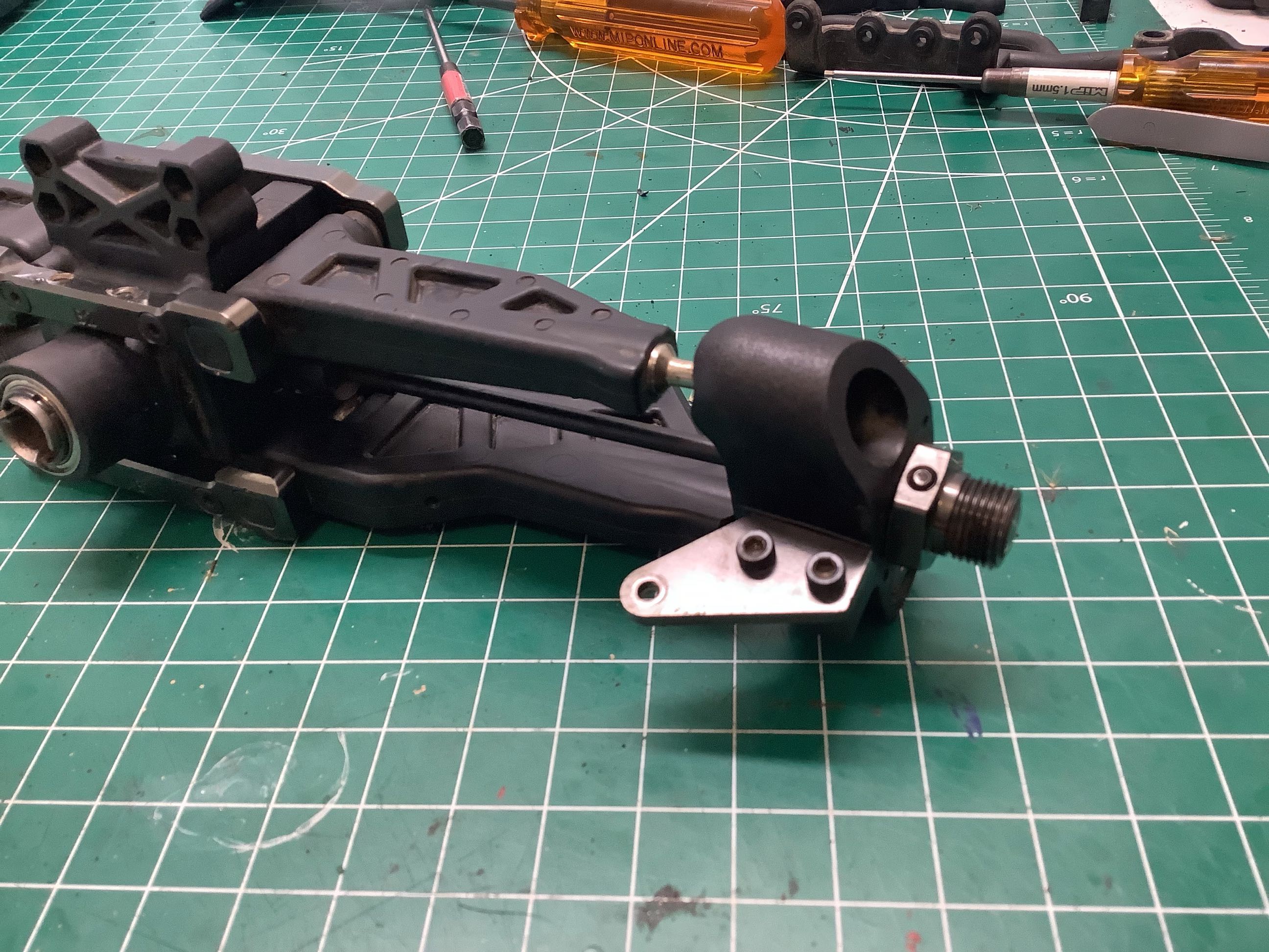
Here I've added the upright, the hubs, and the upper suspension rods, but I've forgotten something rather important: the axles.
This model uses nice CVD axles with huge hubs and 17mm hexes. The
picture on the left shows an exploded view of an axle, and on the right
I've installed them along with the sway bar.
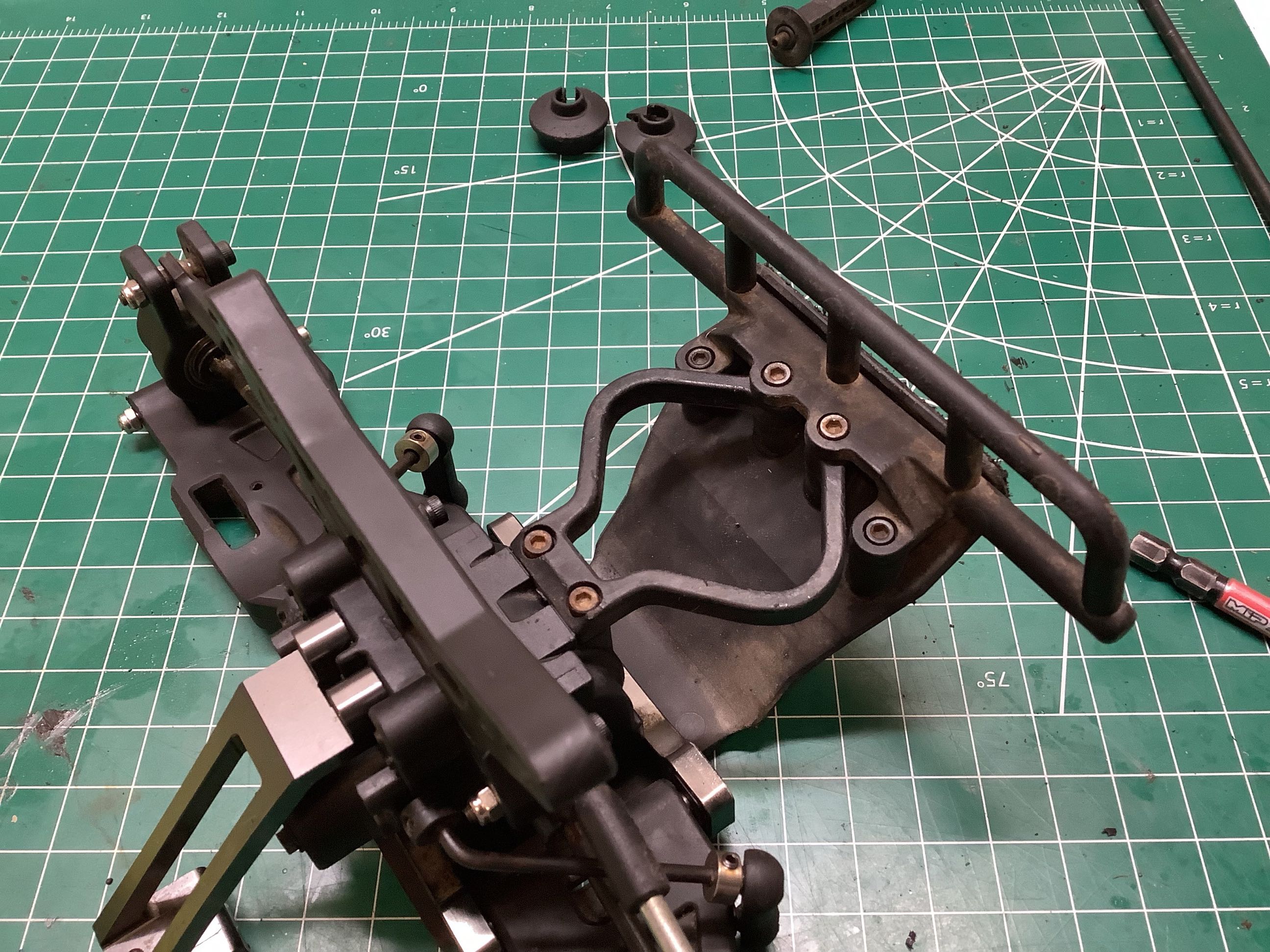
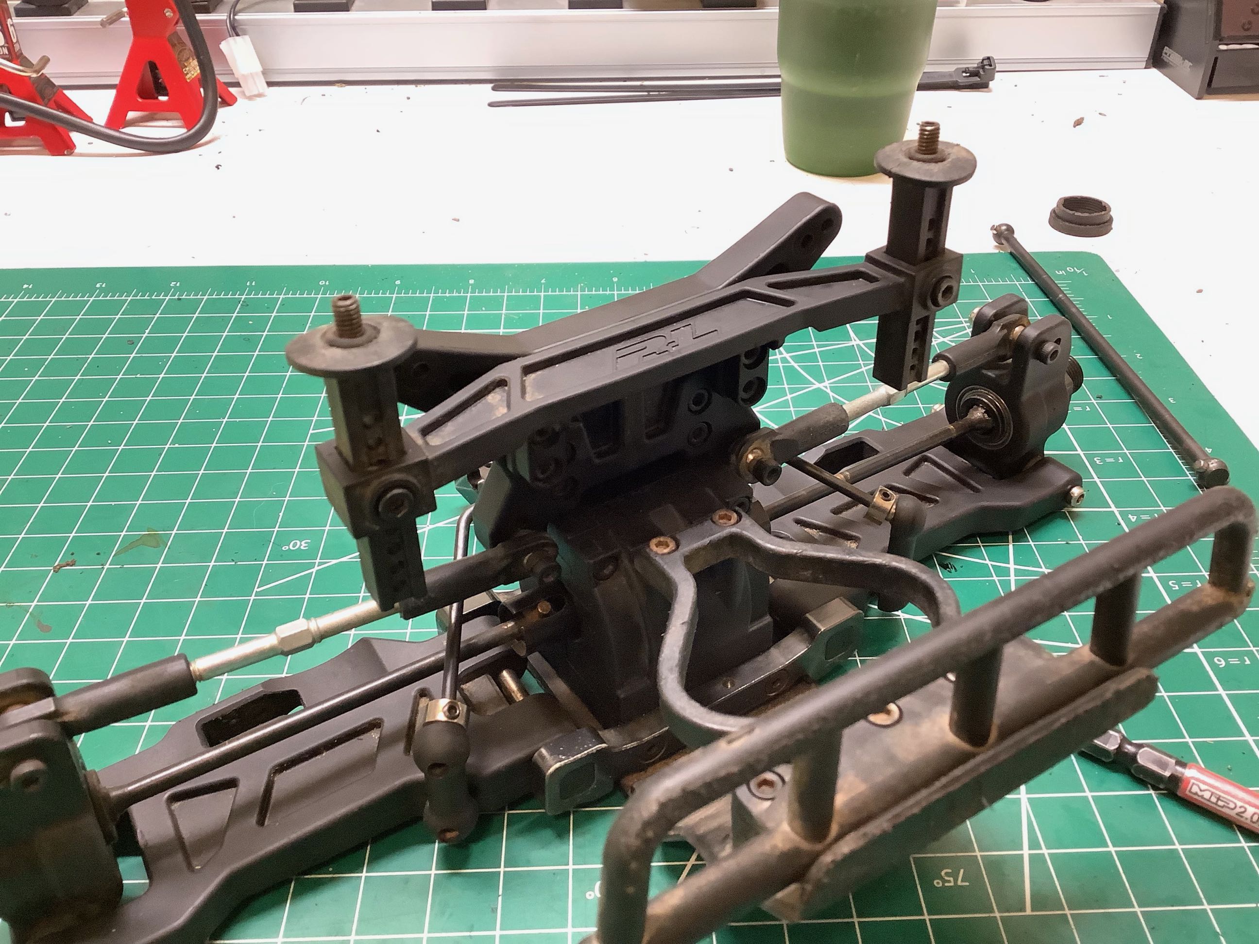
These pictures show the rear bumper and the flexible curved brackets
which absorb impacts. Based on the kind of punishment this chassis
has already withstood, I can confirm that the design is effective.
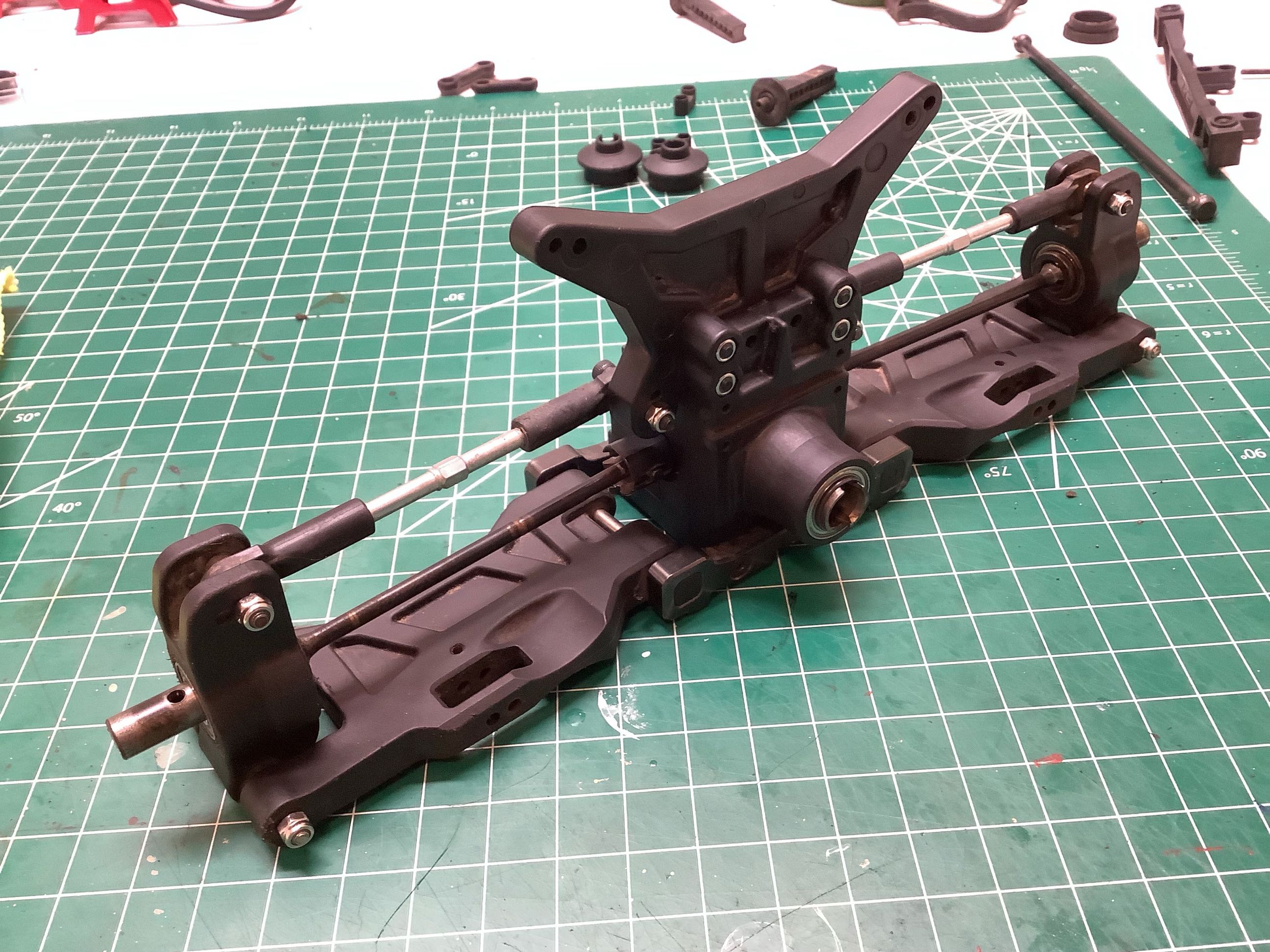
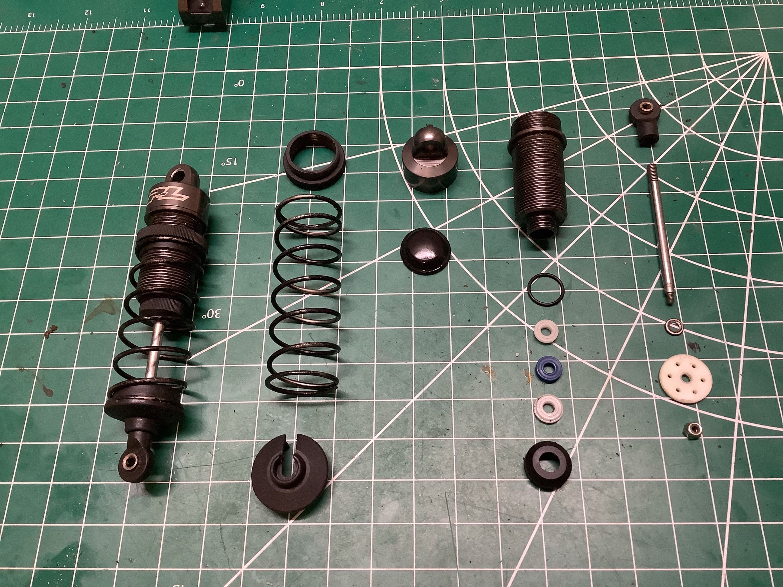
Time to build the massive bore aluminum shocks. Pro-line has been
known for making high quality shocks for years, so these are predictably
excellent. On the right they have been installed and the rear
suspension module is complete.
The front suspension module is very similar to the rear, so I'll only
concentrate on the differences here. We start with the same
differential and a very similar housing. Whereas the rear
suspension has rods for the upper arms, the front uses wishbones top and
bottom. This is necessary for the pillow ball steering system,
but it also adds a lot of stiffness to the steering hubs under
braking. Note the position of the dots on the plastic inserts.
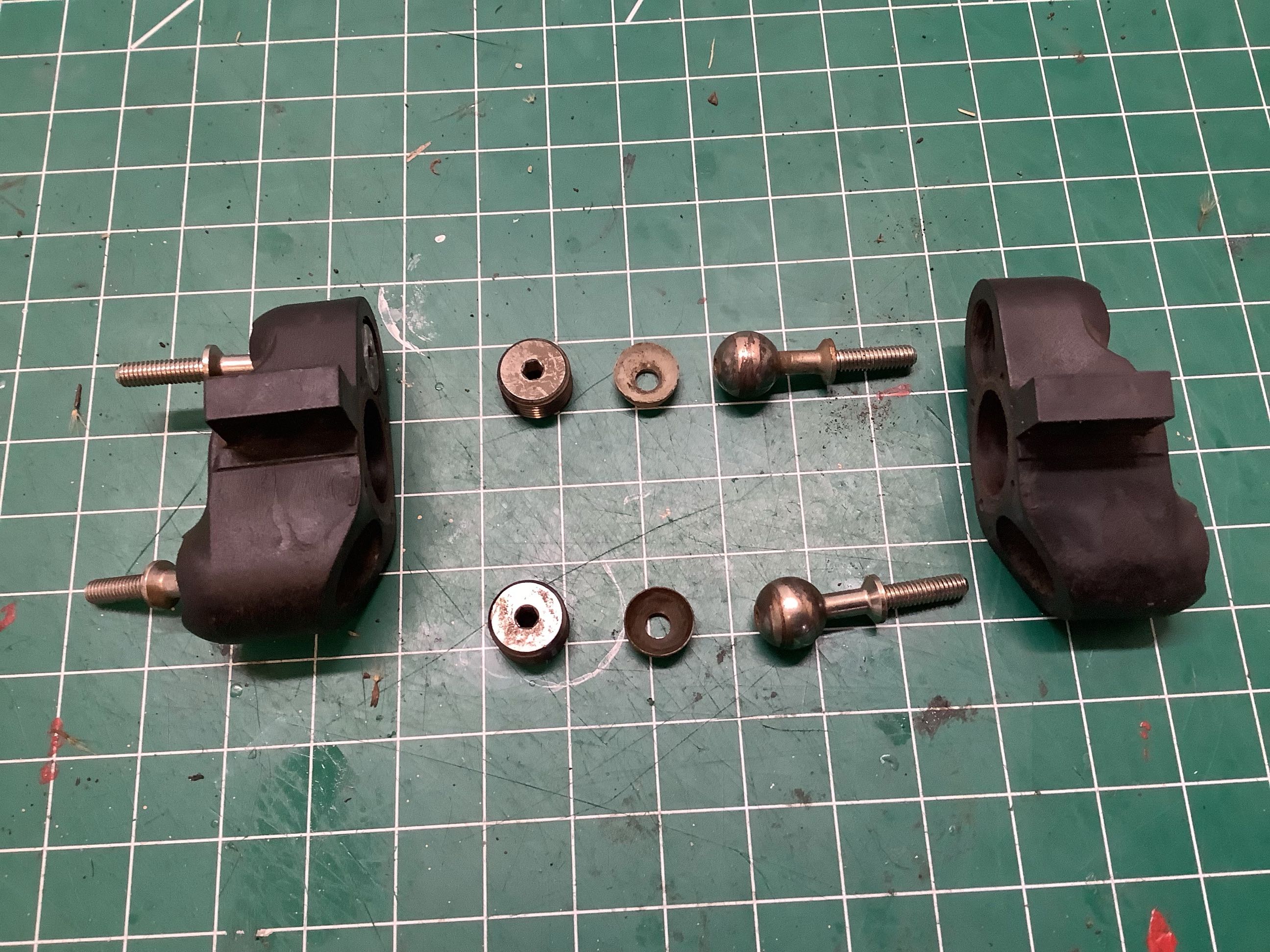
Here are the hubs for the pivot ball suspension. The balls use
large 4mm threads for strength, and the mating cups are Delrin for wear
resistance. The aluminum plugs tighten the cups against the balls
and control the slop and the friction in the joint. The right hand
picture shows the installed hubs and the aluminum steering plates.
Note that the upper joints are further inboard than the lower resulting
in kingpin inclination. From a side view you can see the caster
angle as well. Camber is adjustable by turning in the ball joints
more or less.
Here I've added the shock tower, the shocks, the body mounts, and the
steering links. This completes the front suspension module.
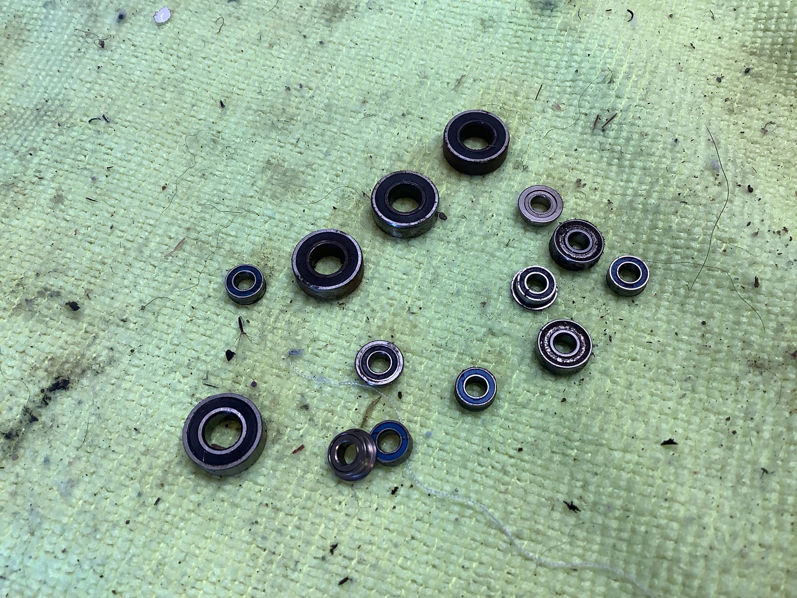
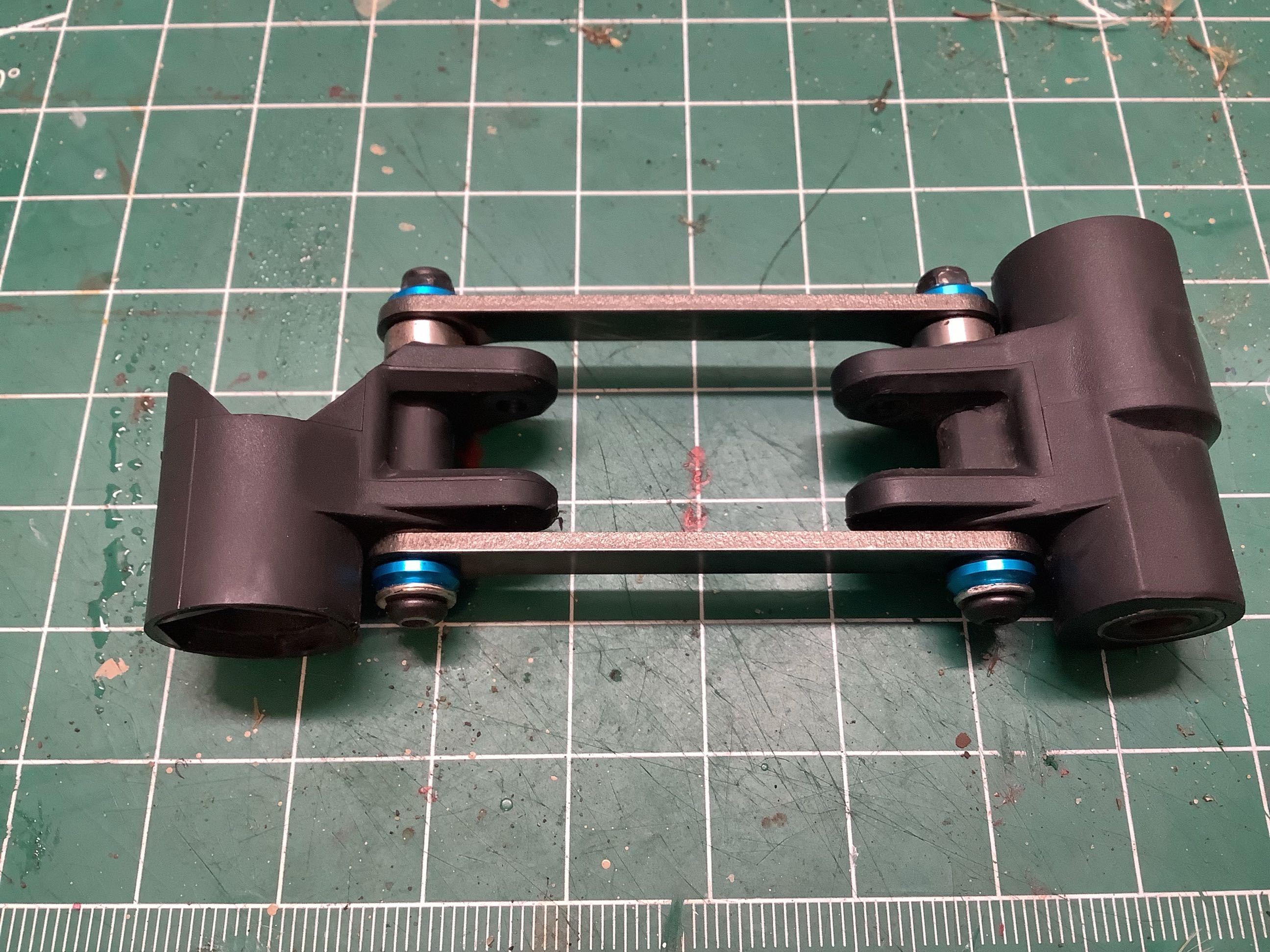
This is not the stock steering system. The version I am
using has two cross links instead of one which greatly improves the
response (see upgrade page). The stock
version has a single link and a total of 6 bearings including a set of
tiny flanged bearings for the links which don't last long. The
upgraded version uses 14 bearings as shown on the left. The links
now put the cranks in double shear so there is no bending on the links.
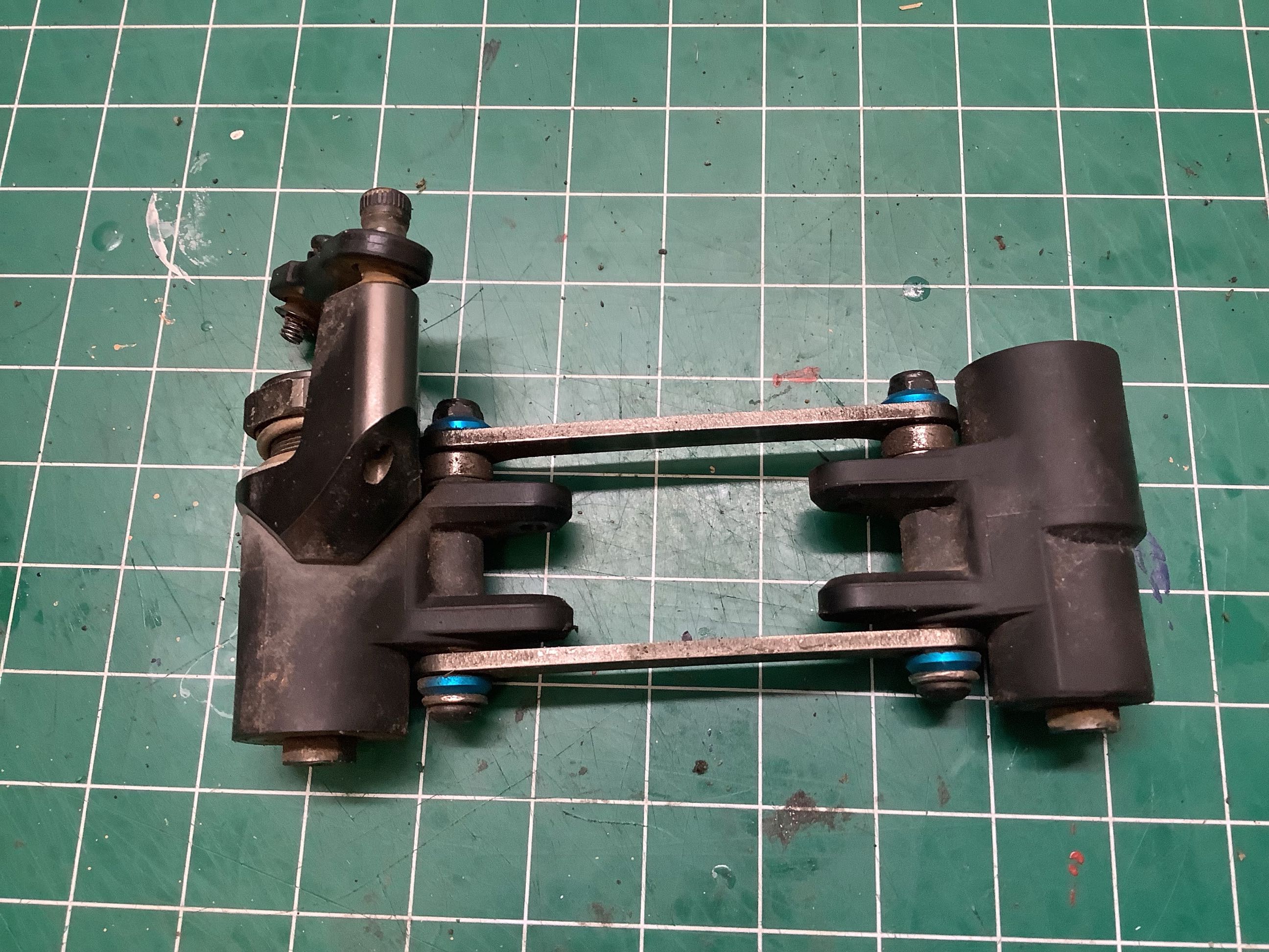
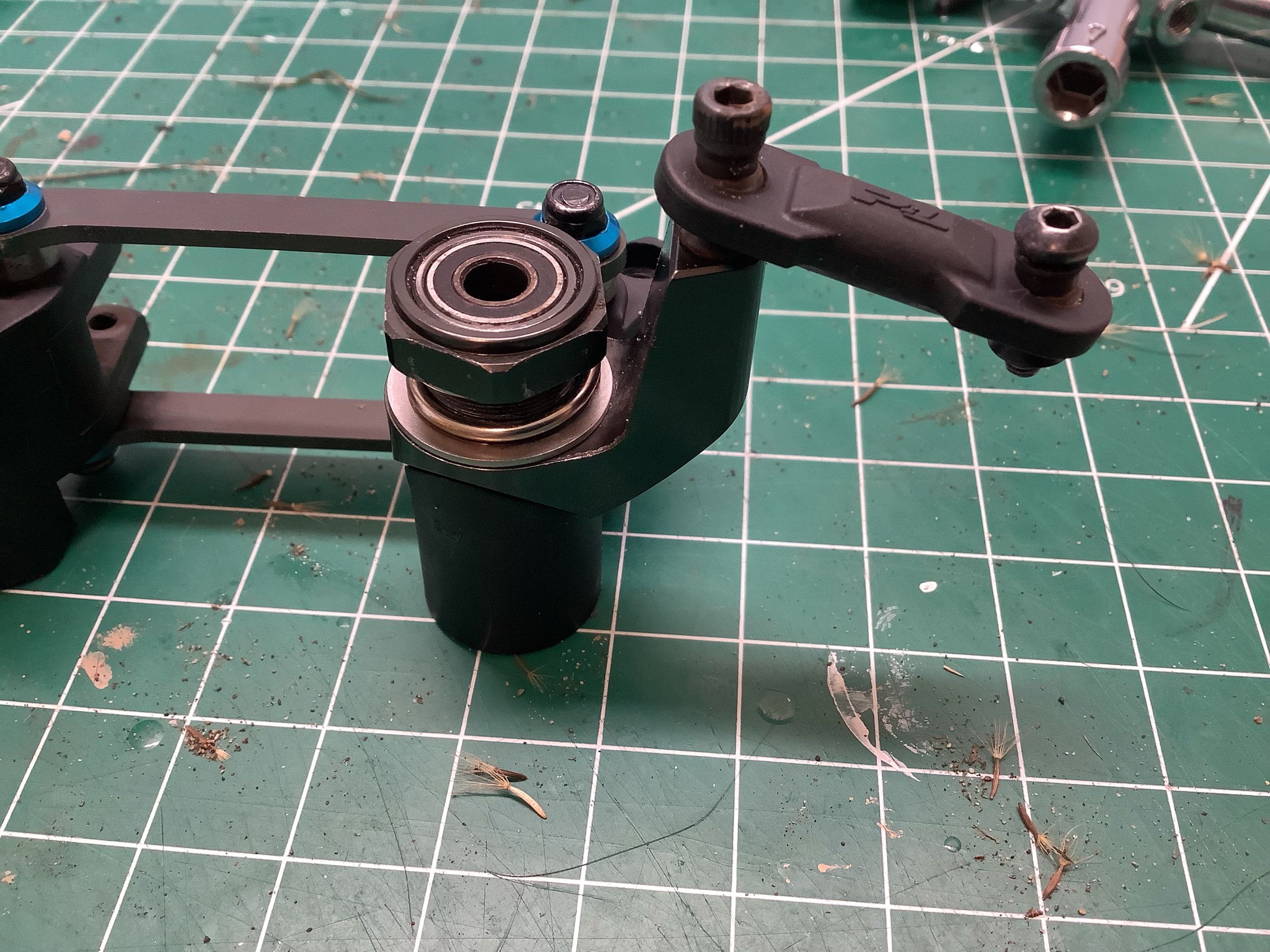
Here you can see my upgraded aluminum servo saver arm which is an
absolute necessity. The picture on the right shown the nut used to
adjust the servo saver preload.
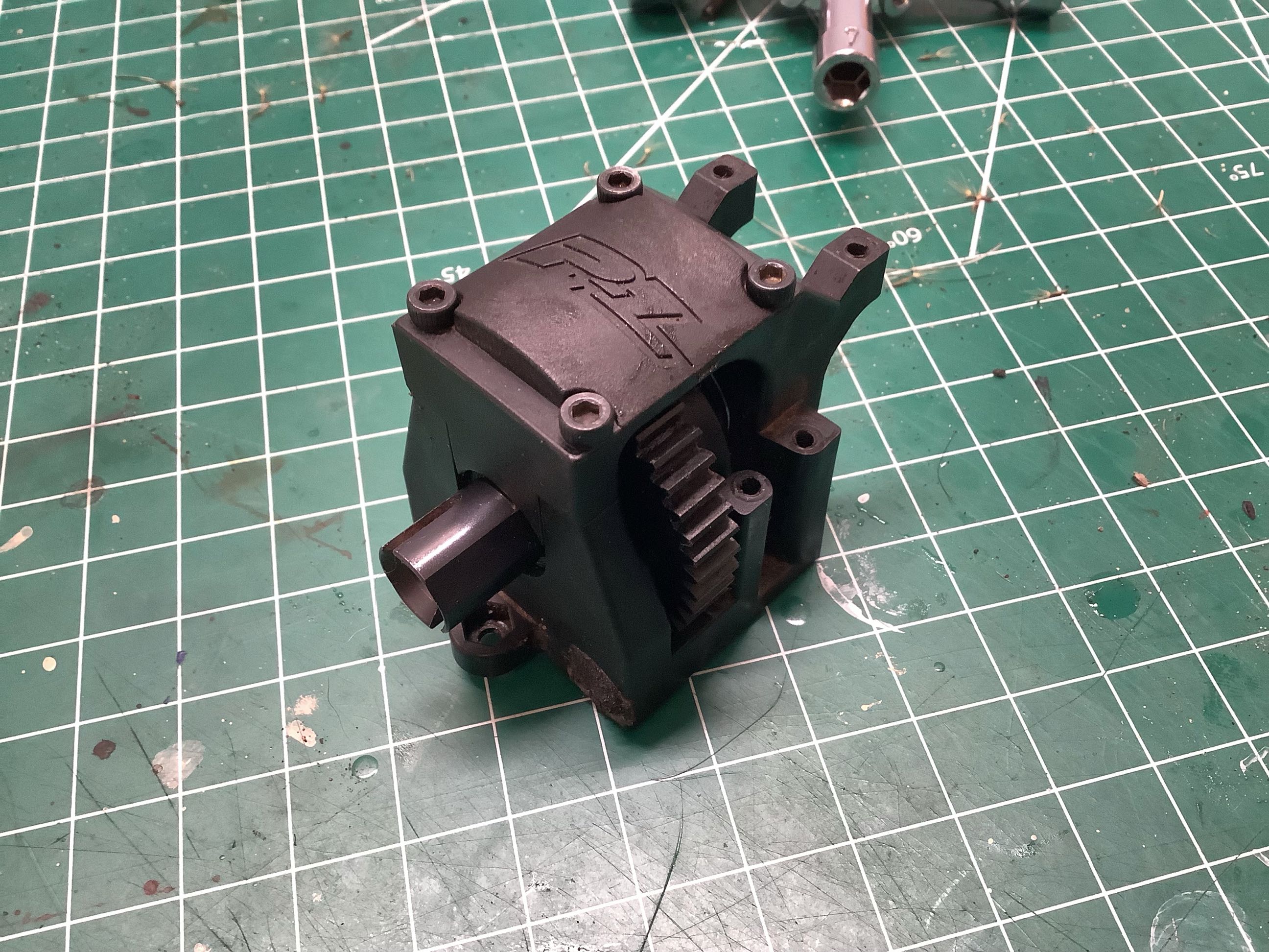
The internal parts of the center differential are just like the front
and rear, but this one is filled with million weight fluid so it is
practically locked. It also uses a spur rather than a bevel for
the ring gear. This is also the spur gear which mates with the
motor pinion. It is plastic but incredibly tough. The gears
are Mod 1 (25.4p).
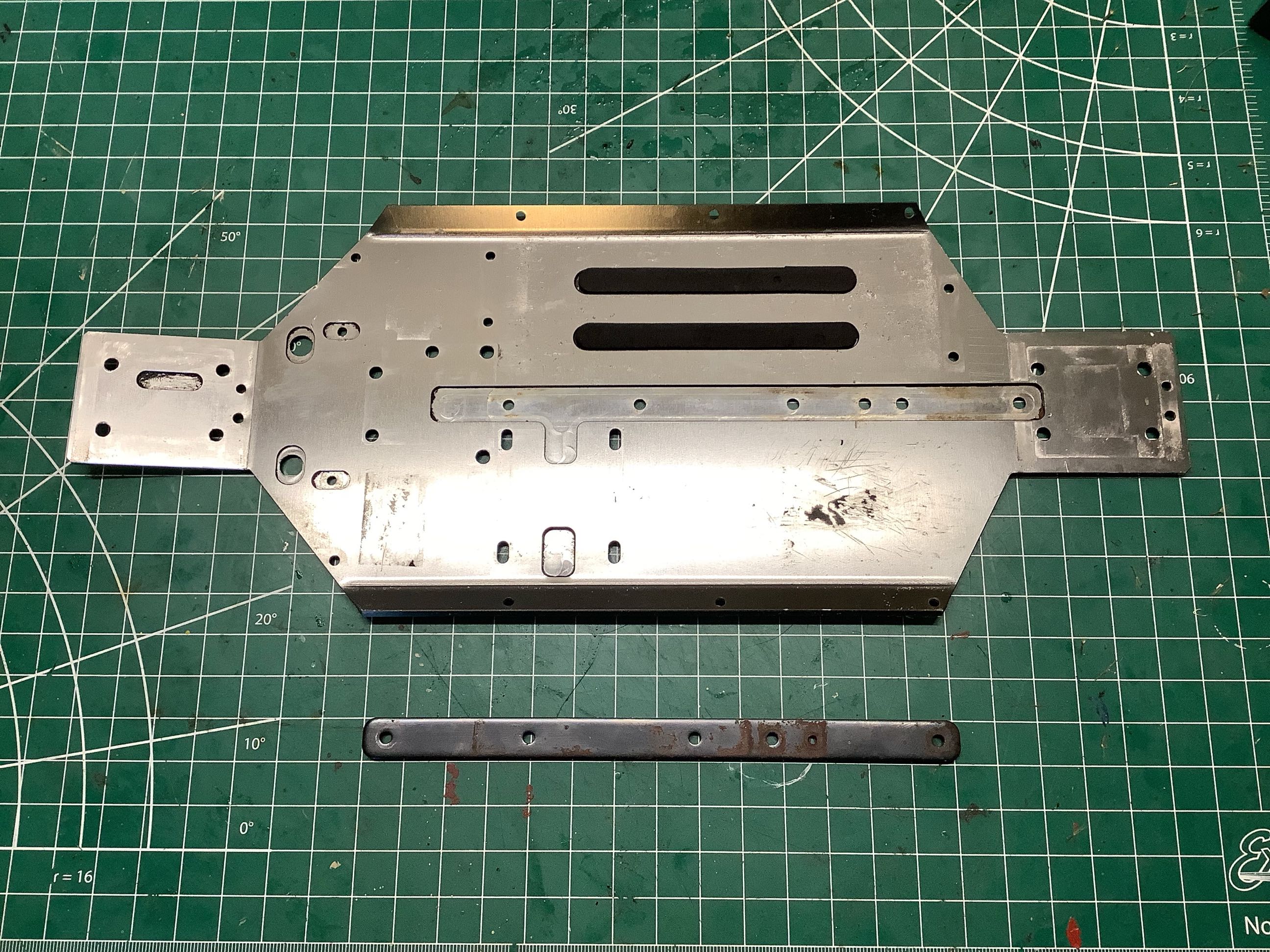
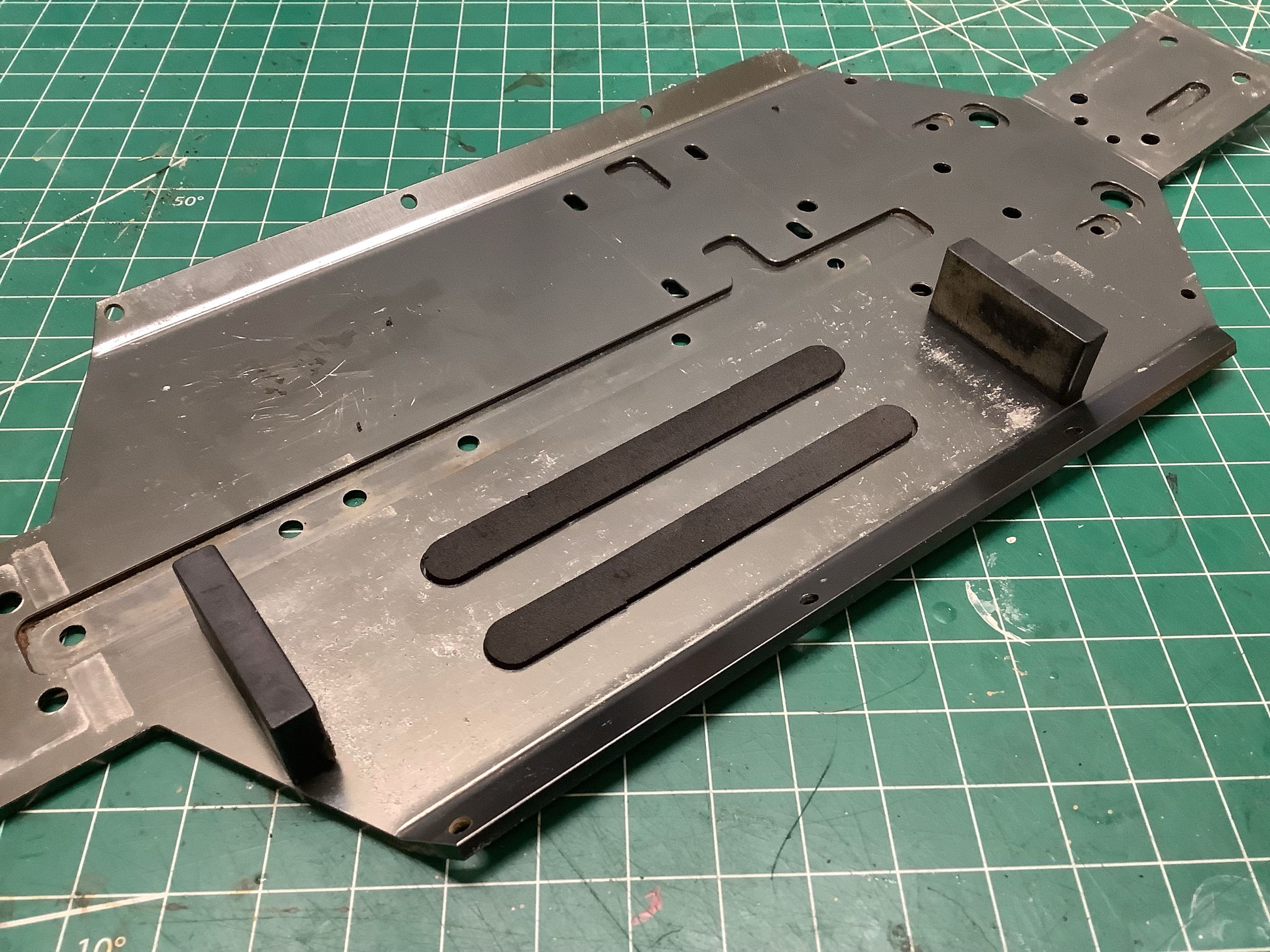
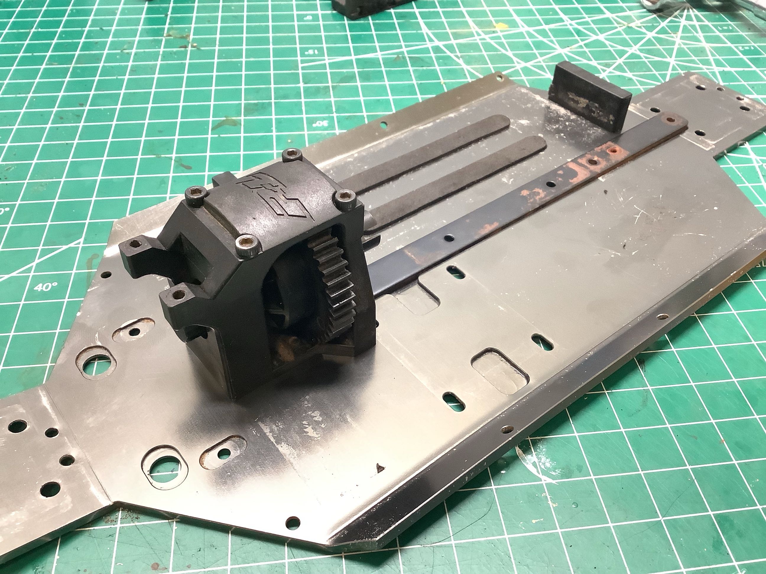
The chassis is a solid aluminum plate which has been formed with bends
for stiffness and also contains machined pockets and countersinks.
Just in case it wasn't already stiff enough, a steel plate (shown lower
left) is bolted down the center for even more rigidity. The
blocks on the right support the battery and the foam strips cushion it
and keep it from sliding.
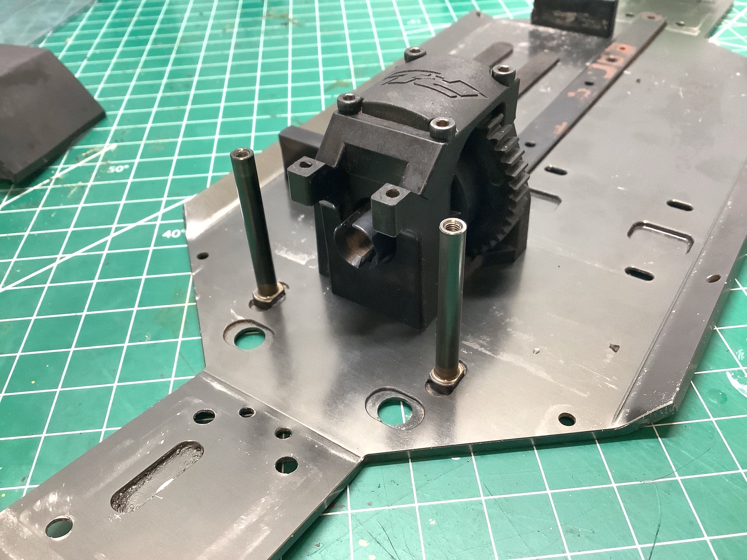
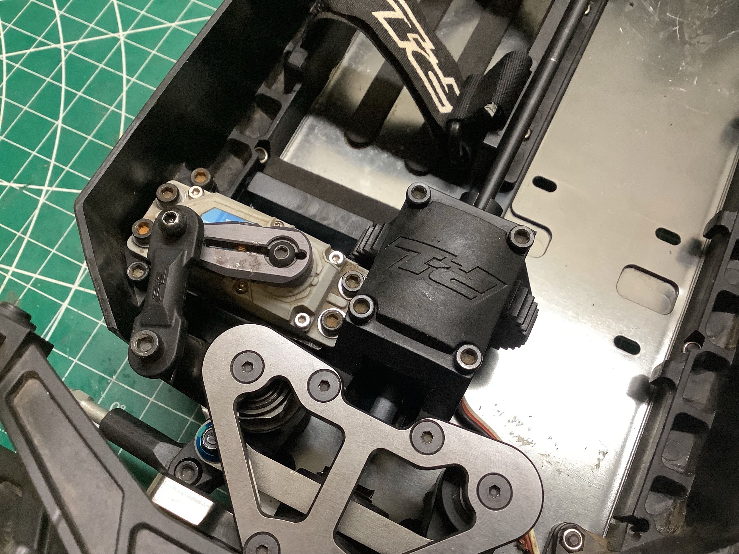
Here I've installed the center differential by bolting it to the chassis
plate. On the right I've added the posts for the steering
system. Note how they are keyed to the chassis plate so they can't
rotate.
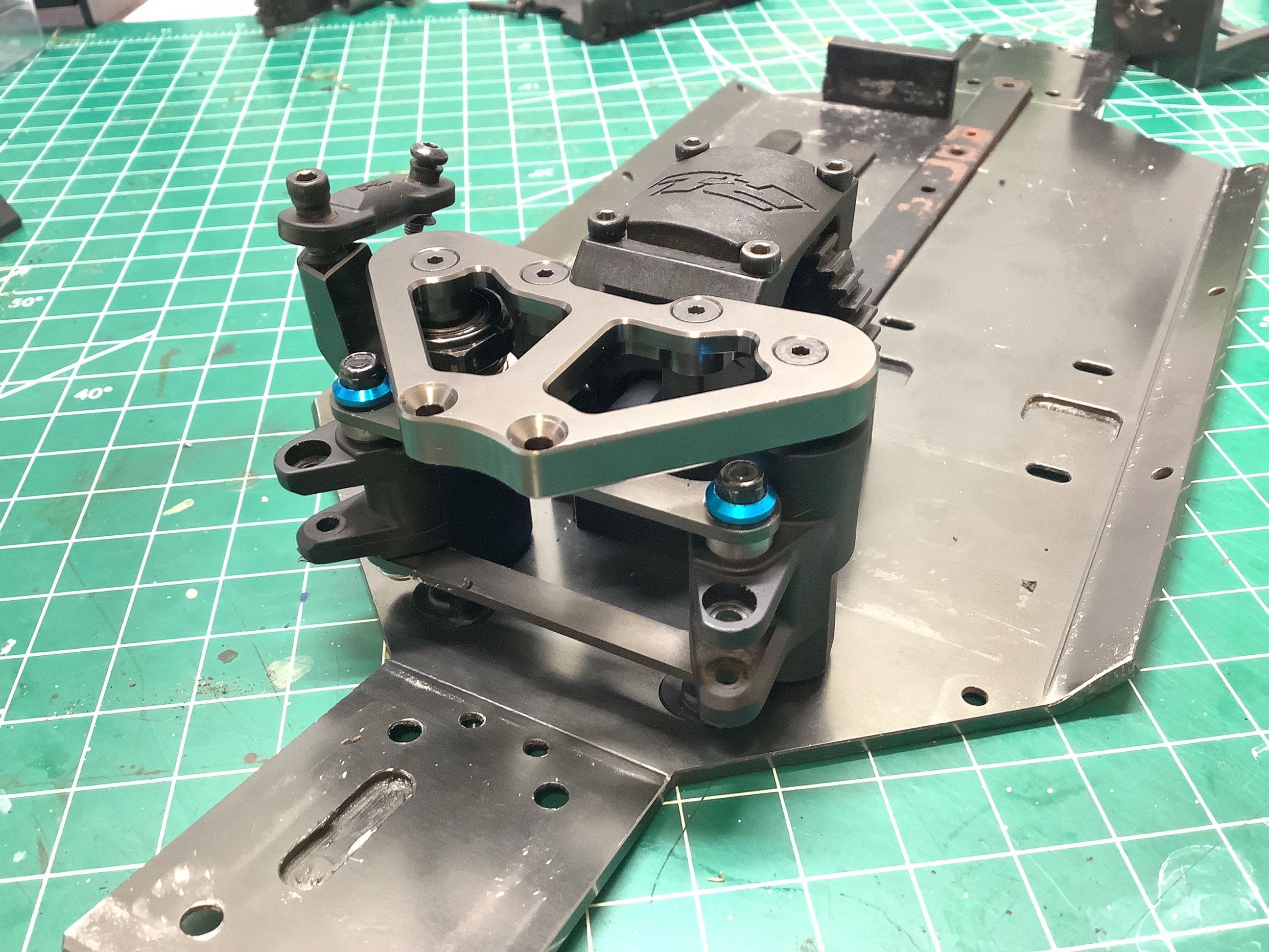
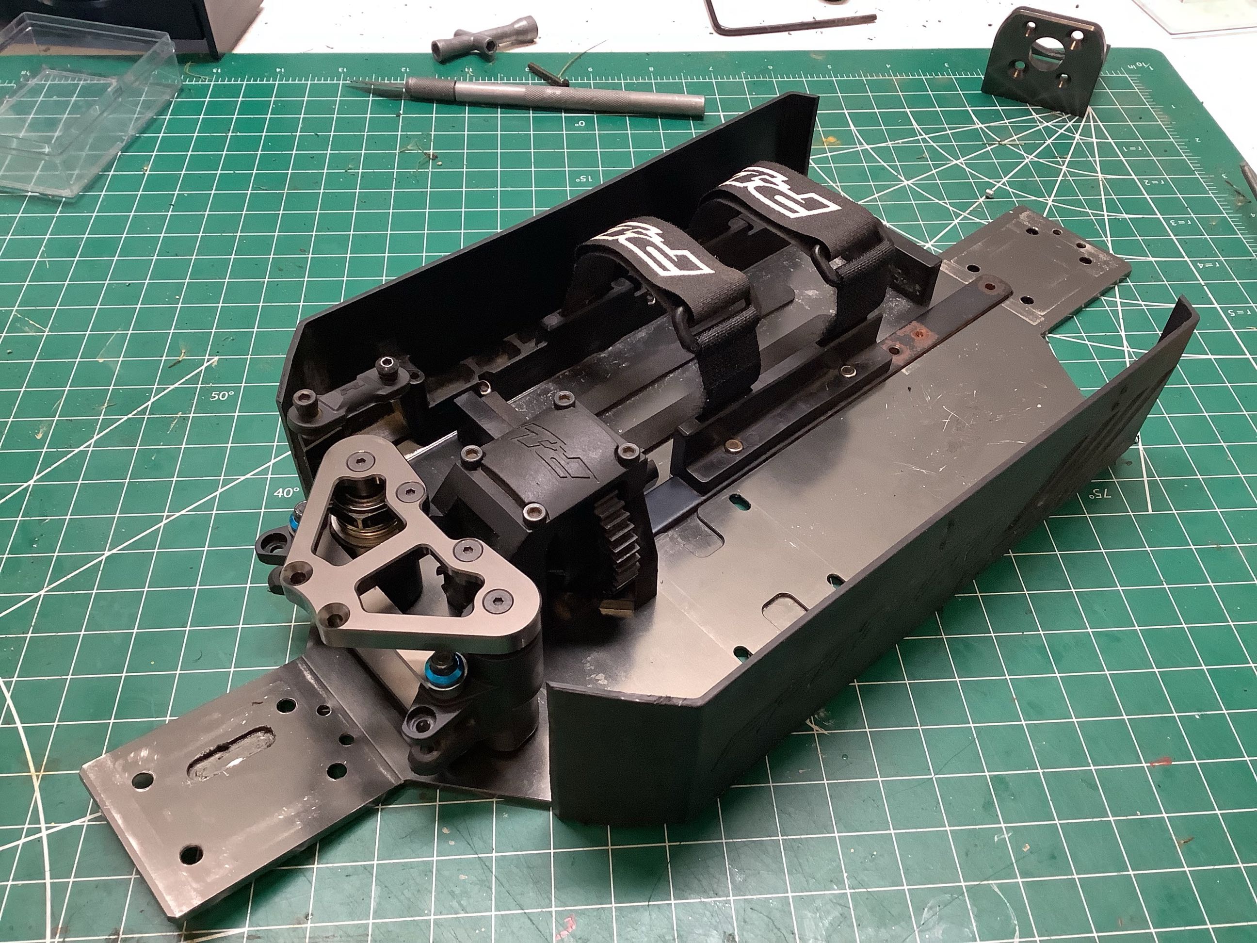
Here I've installed the steering cranks and the upper upgraded aluminum
bracket which will also brace the front suspension. On the left
I've added the battery straps and the plastic side shields. They
may be only plastic with a low modulus, but considering that the moment
of inertia varies with the cube of the height, they add a non-trivial
amount of stiffness to the chassis.
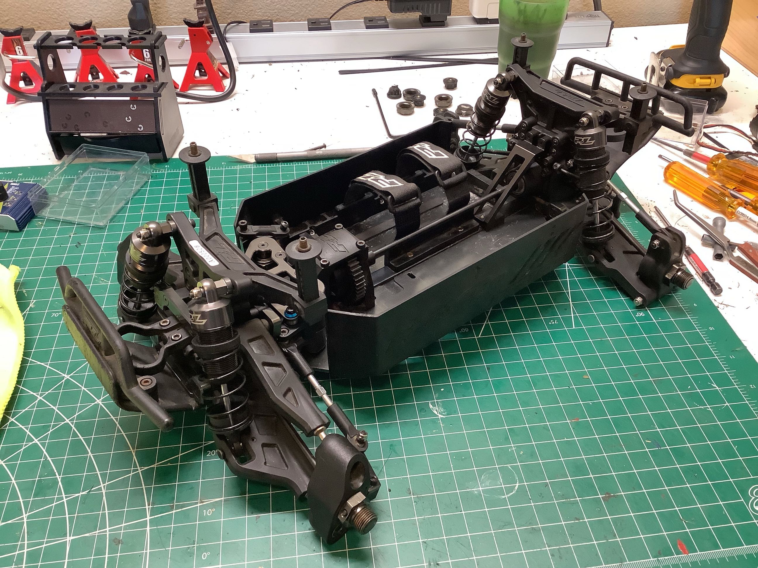
Now I've added the front and rear suspension modules basically
completing the rolling chassis. It just needs electronics to
run. On the right I've added the steering servo using a clamping
steel servo horn.
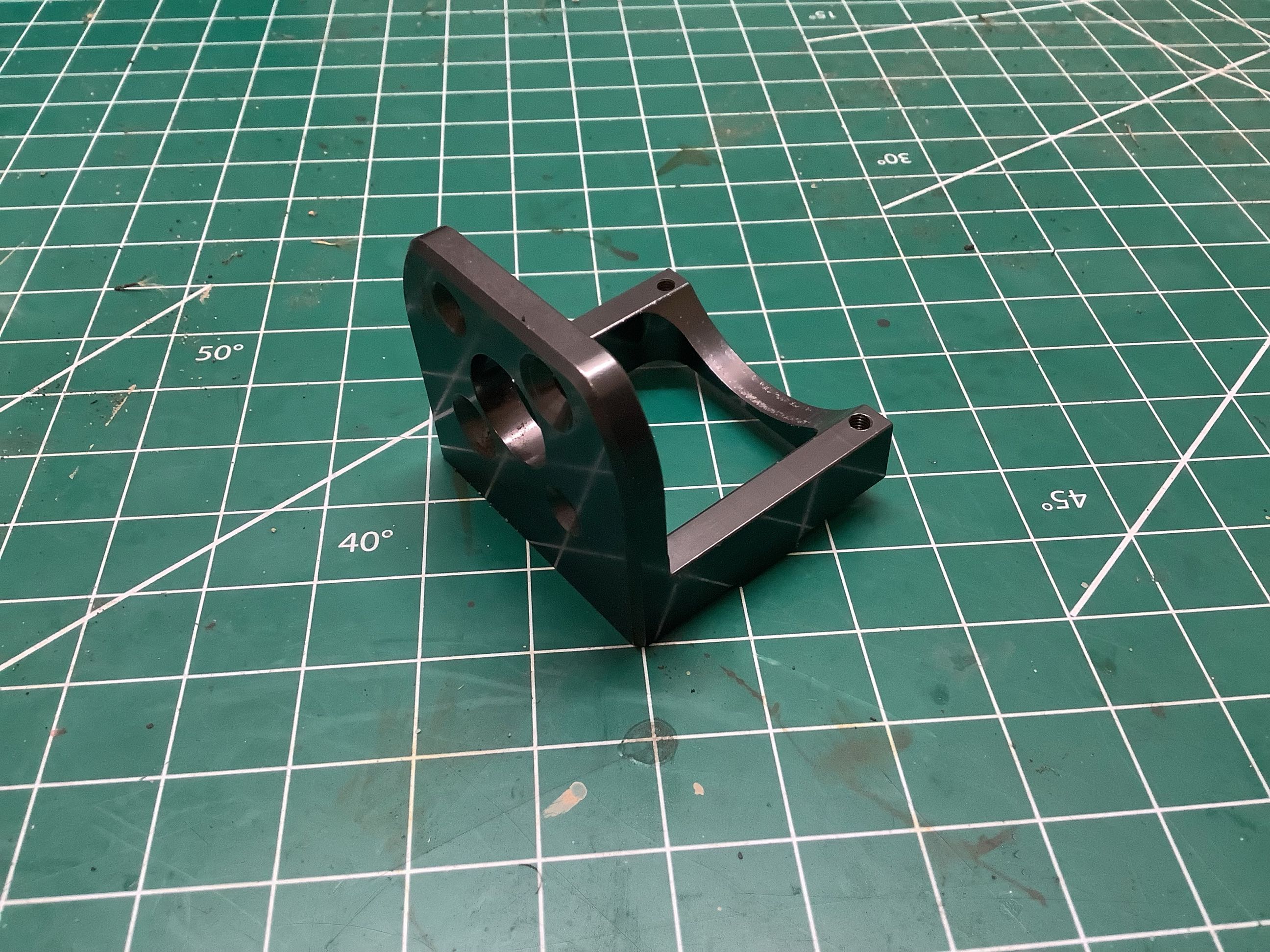
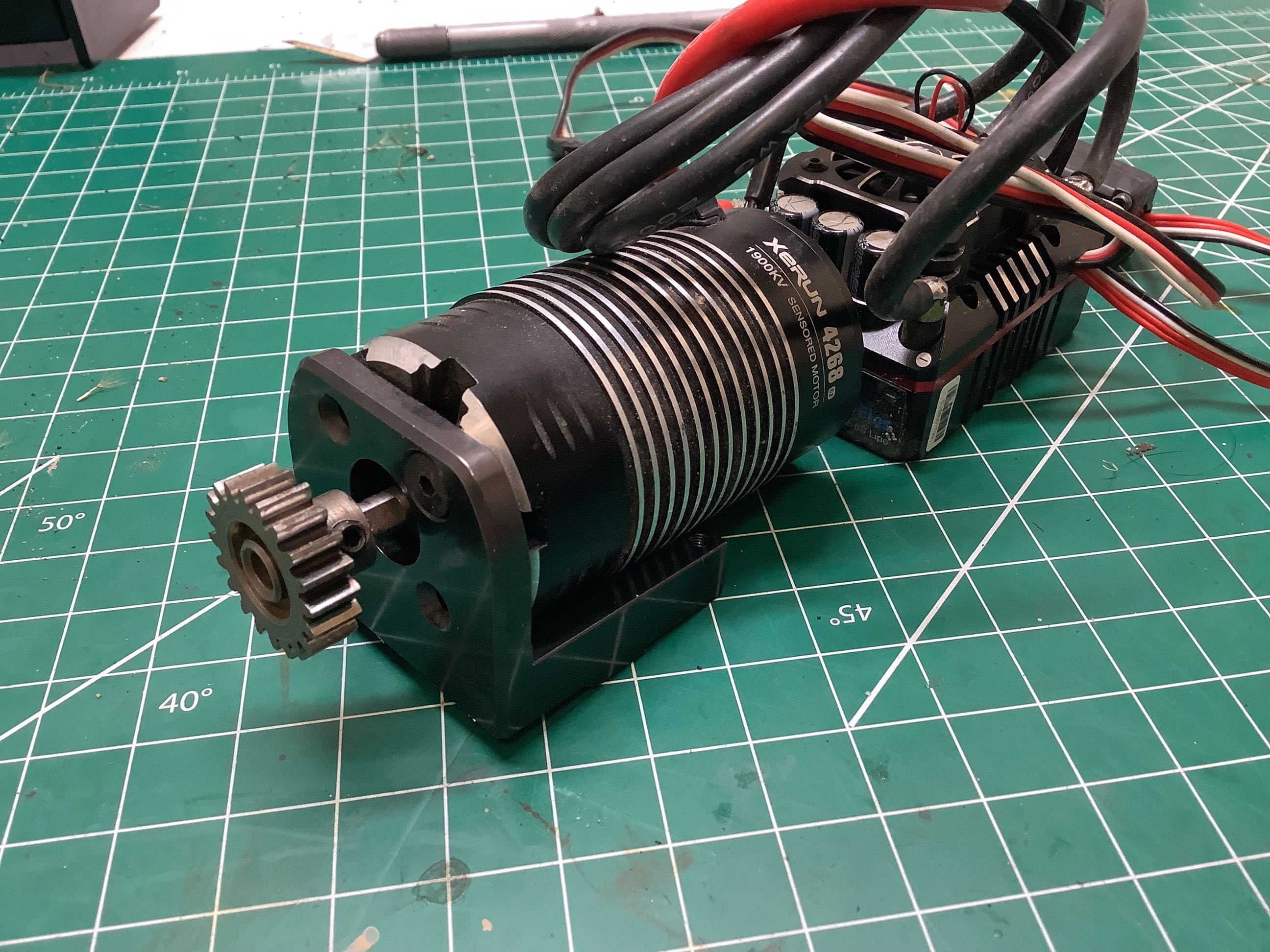
The machined aluminum motor mount is substantial which is a good thing
given the giant 1/8 scale motor I used. And look at the size of
that steel pinion!
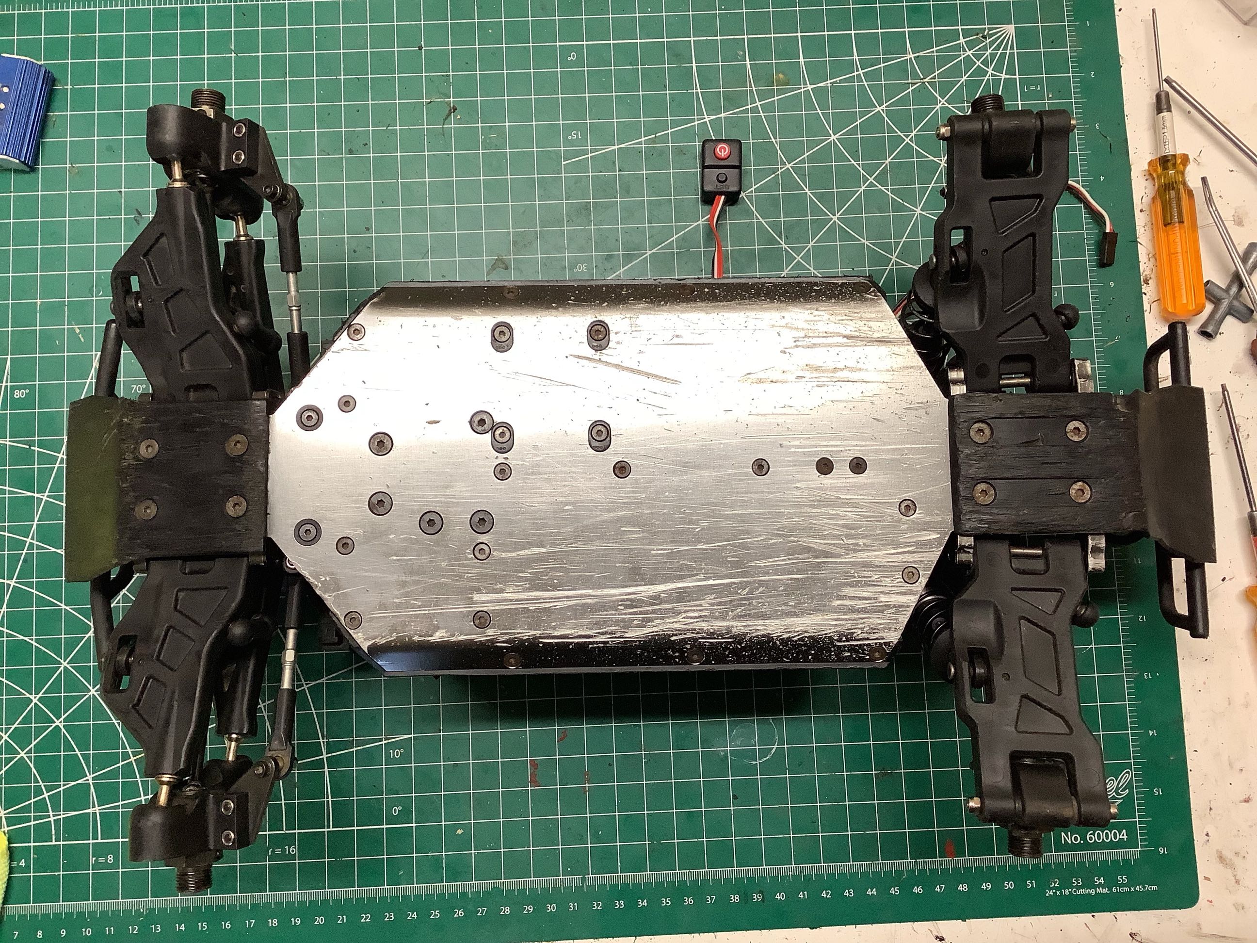
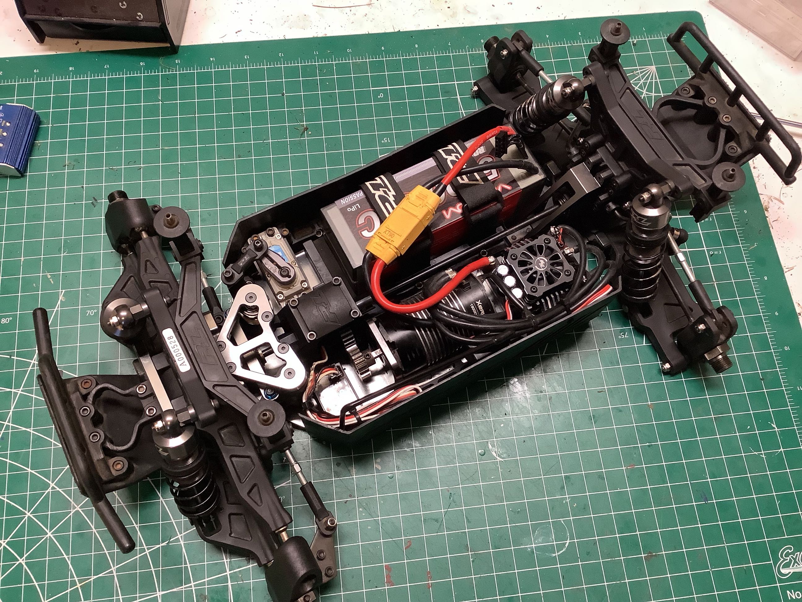
From the
bottom of the chassis you can see that all the screw heads are
countersunk for a smooth surface. From above you can see the
completed electronics install including the 4s battery. All
available space has been consumed.
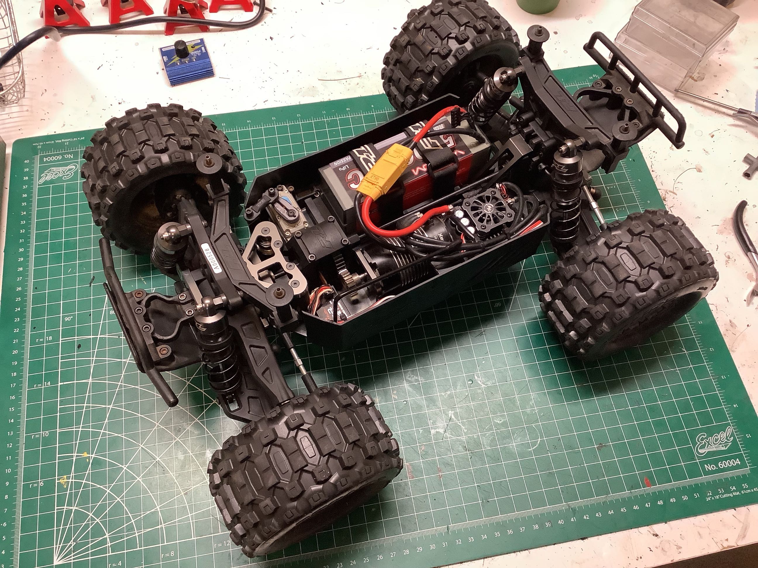
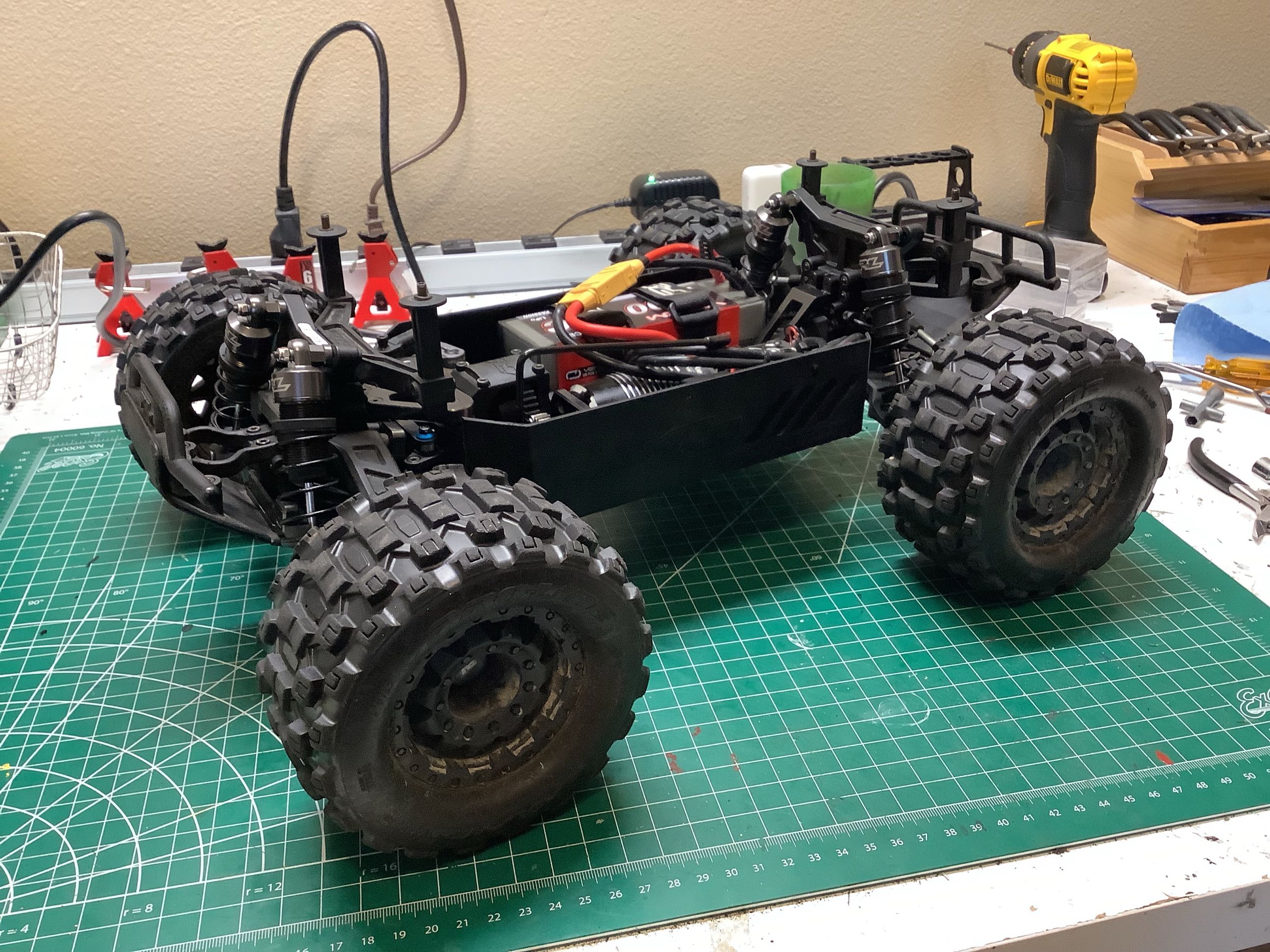
With the installation of the wheels and tires, the model is
completed. Note that I am still using the stock tires after 3
years. They show a bit of wear but have held up incredibly well,
all things considered.