Associated RC10 Project
Page 1: Assembly
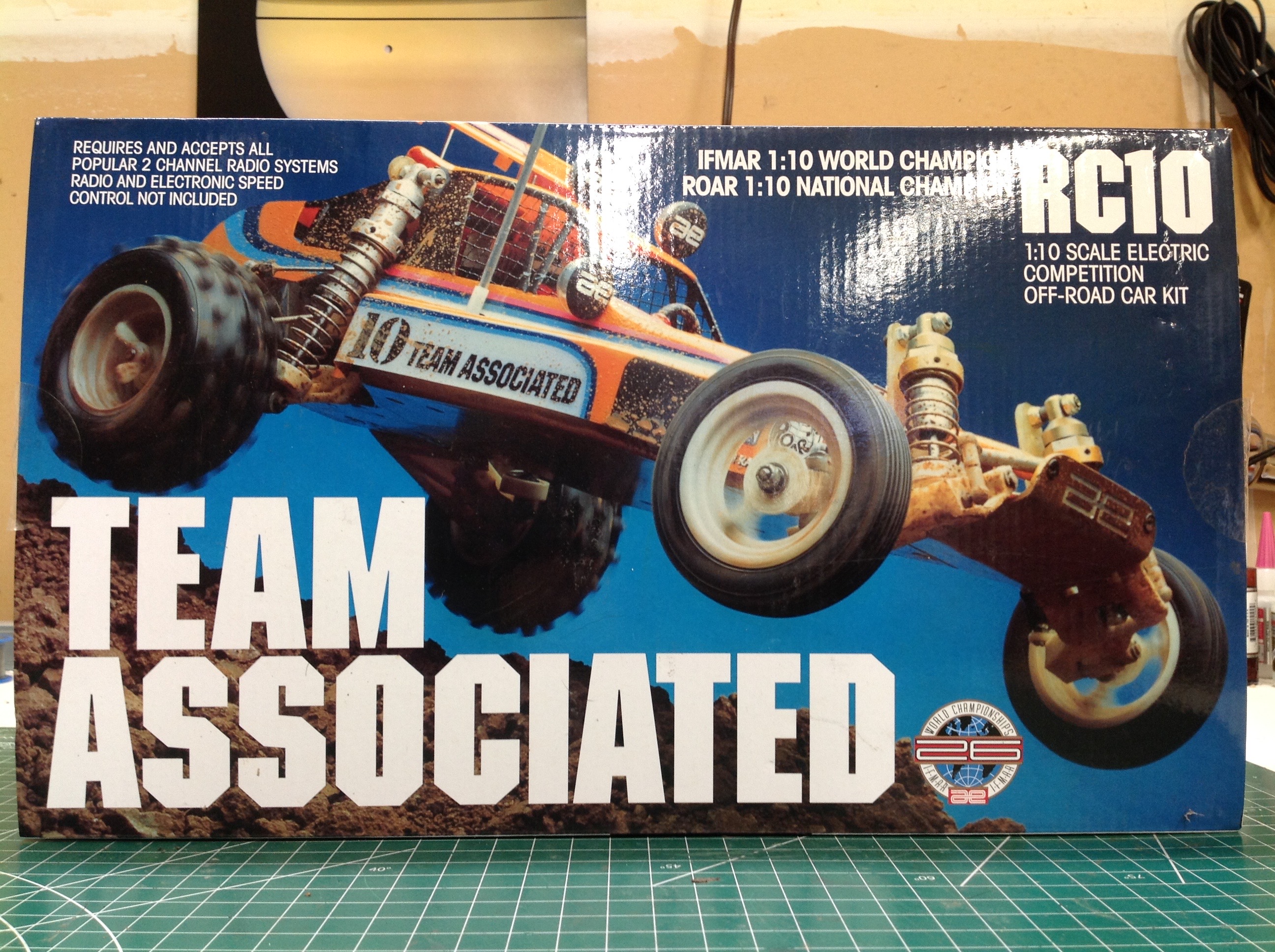
A close look at the box reveals that photo does not actually show the
re-released RC10 Classic, rather it shows the original buggy.
There are several clues, but the shocks in particular are a
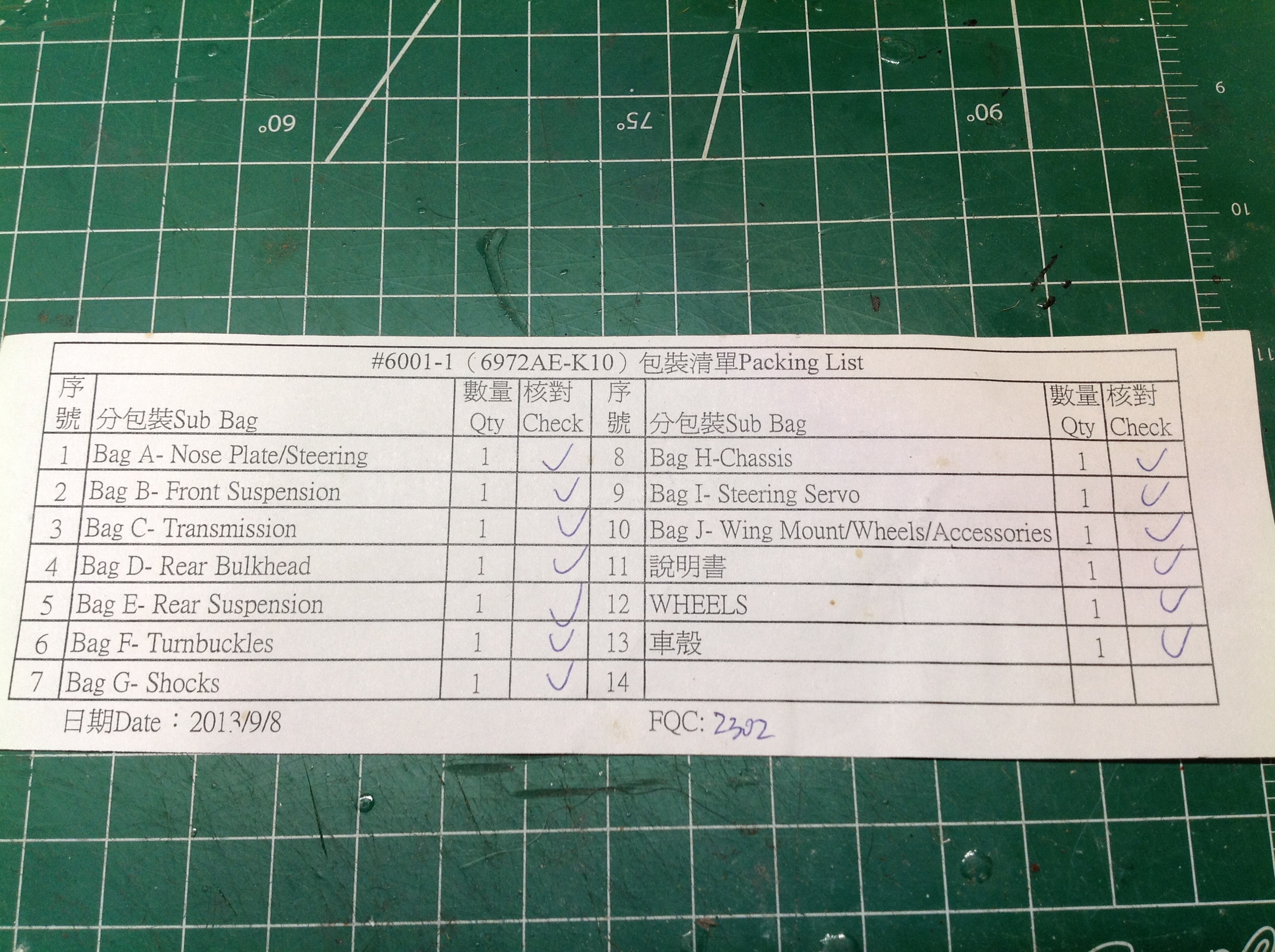
giveaway. It is also interesting to note that this buggy from an
American company has a packing list which does not appear to be entirely
in English.
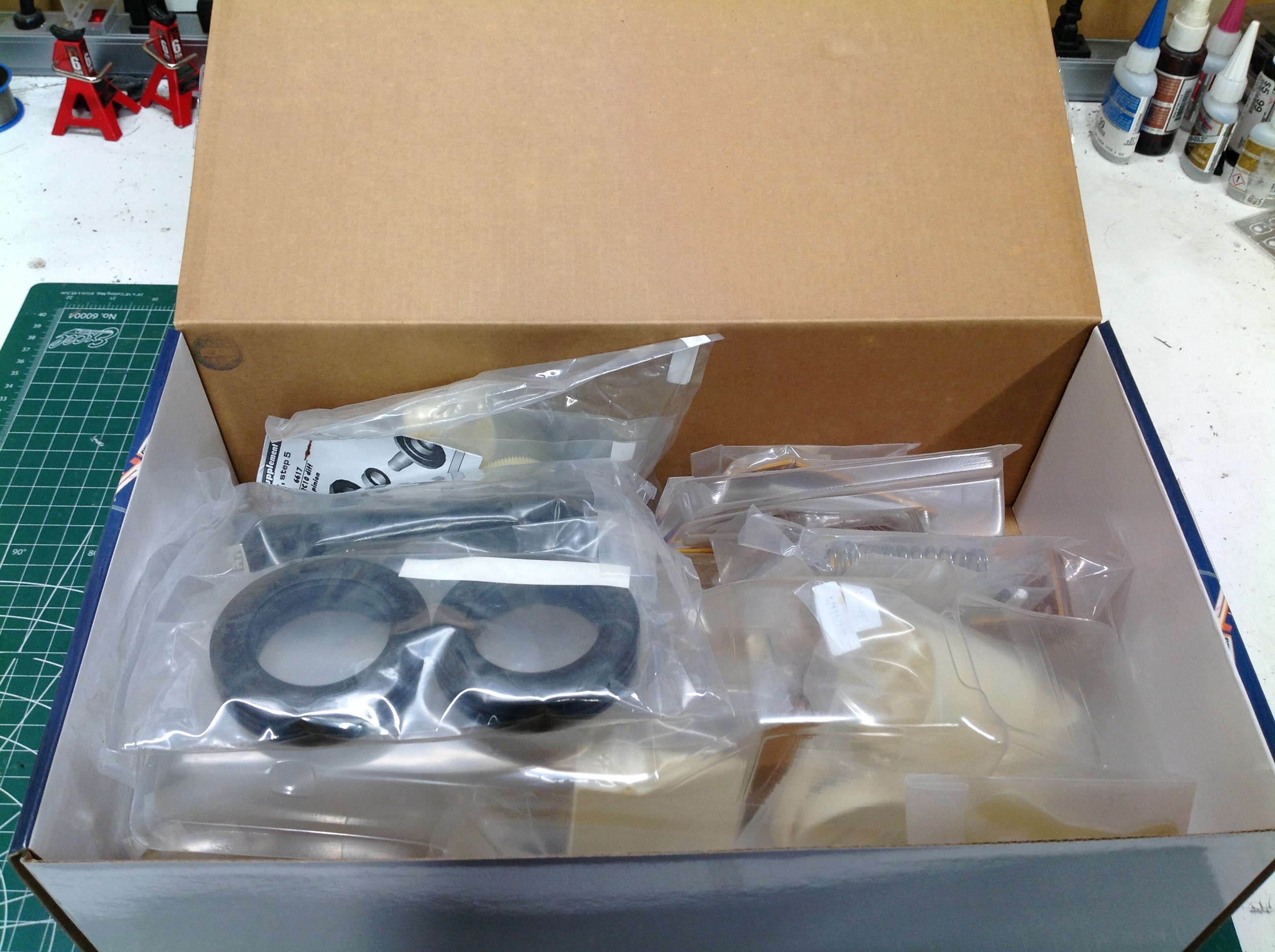
Inside the box are a series of bags labeled A-J which each correspond to
a logical sub-assembly of the model rather than to a specific step in
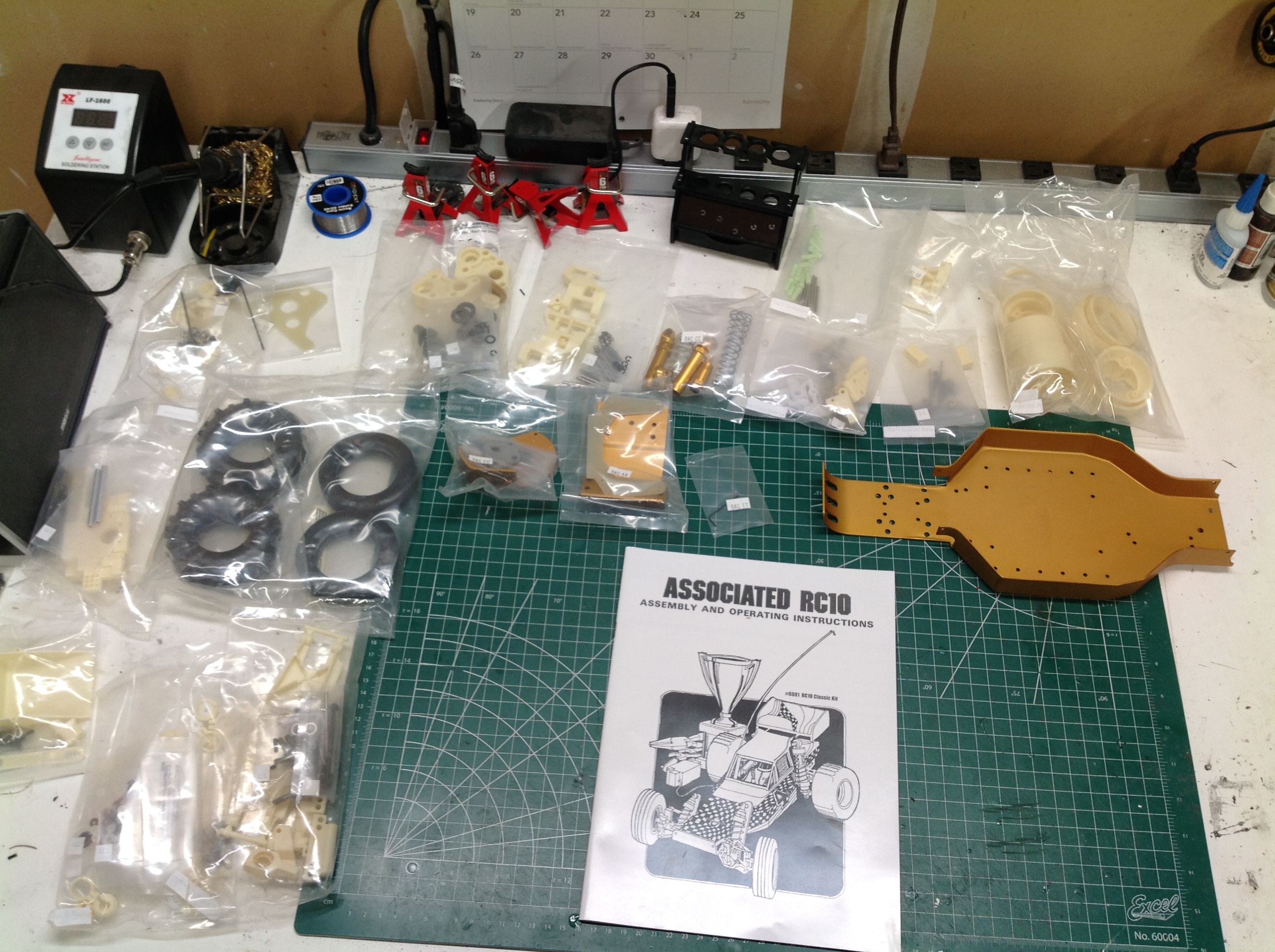
the instructions. The right hand image shows everything arrayed on
the table including the beautiful formed aluminum gold anodized chassis
tub.
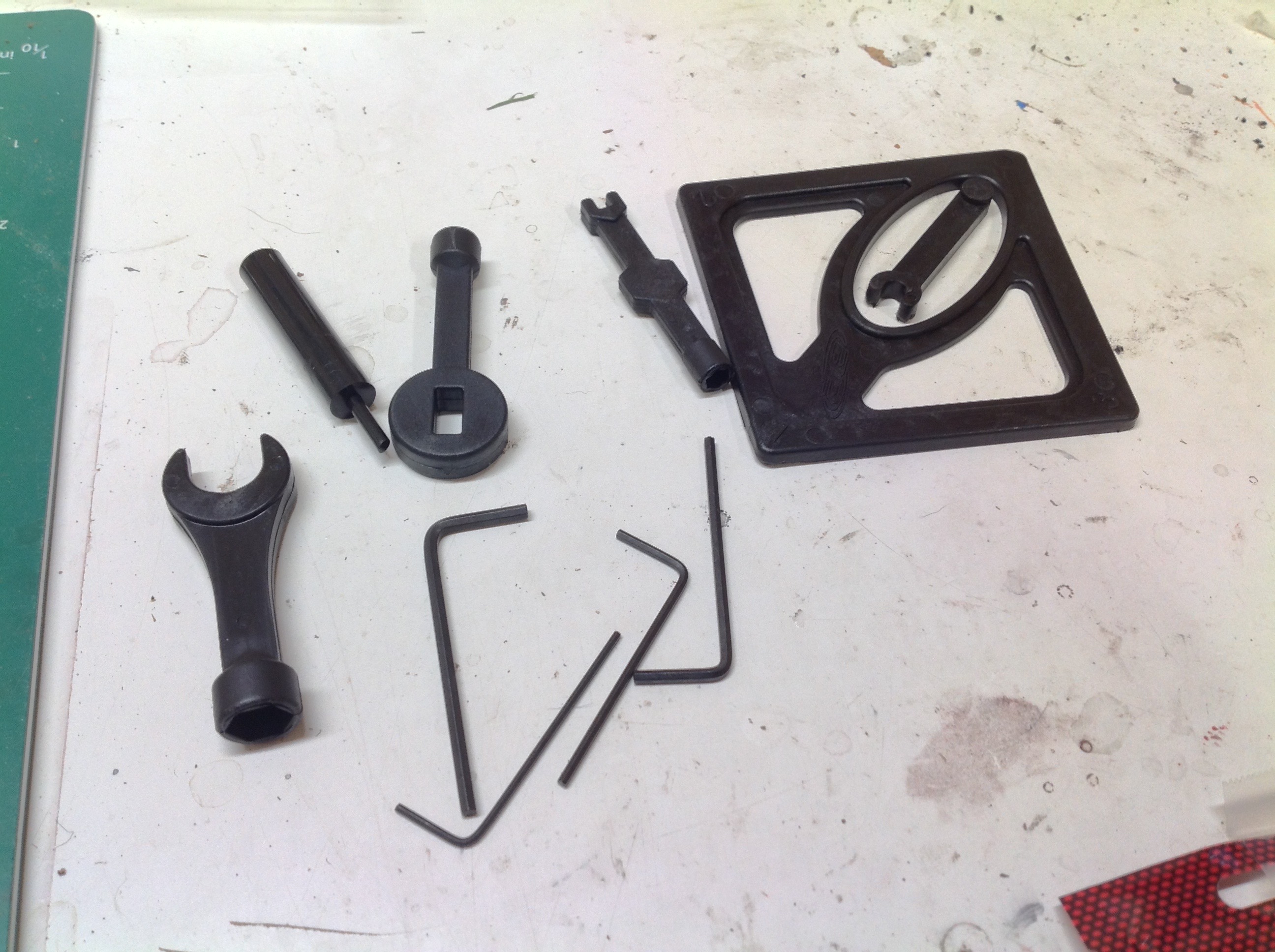
Despite the fact that this kit was clearly produced in China, one very
strange aspect of it's design is that the parts are not metric, they use
Imperial units. All of my build tools are metric so I had to
actually use the array of tools shown on the left which came with the
kit. The rhomboid part is a camber gauge. The open end
wrenches are used for the shocks, and there is even a special tool to
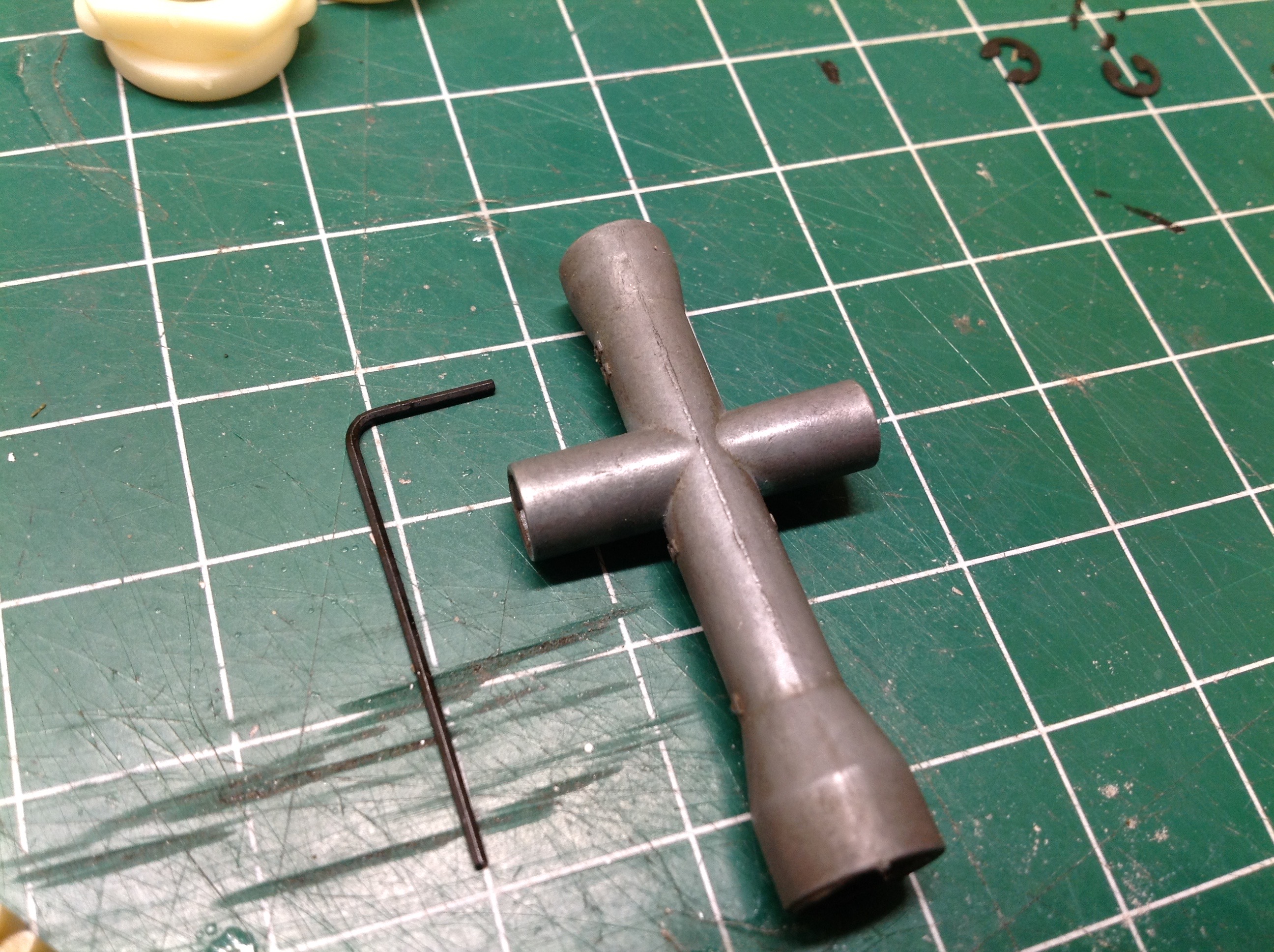
pre-stage the o-rings. The picture on the right compares the
tiniest hex key to a standard cross wrench for scale. I think it
is only 1/32 inch.
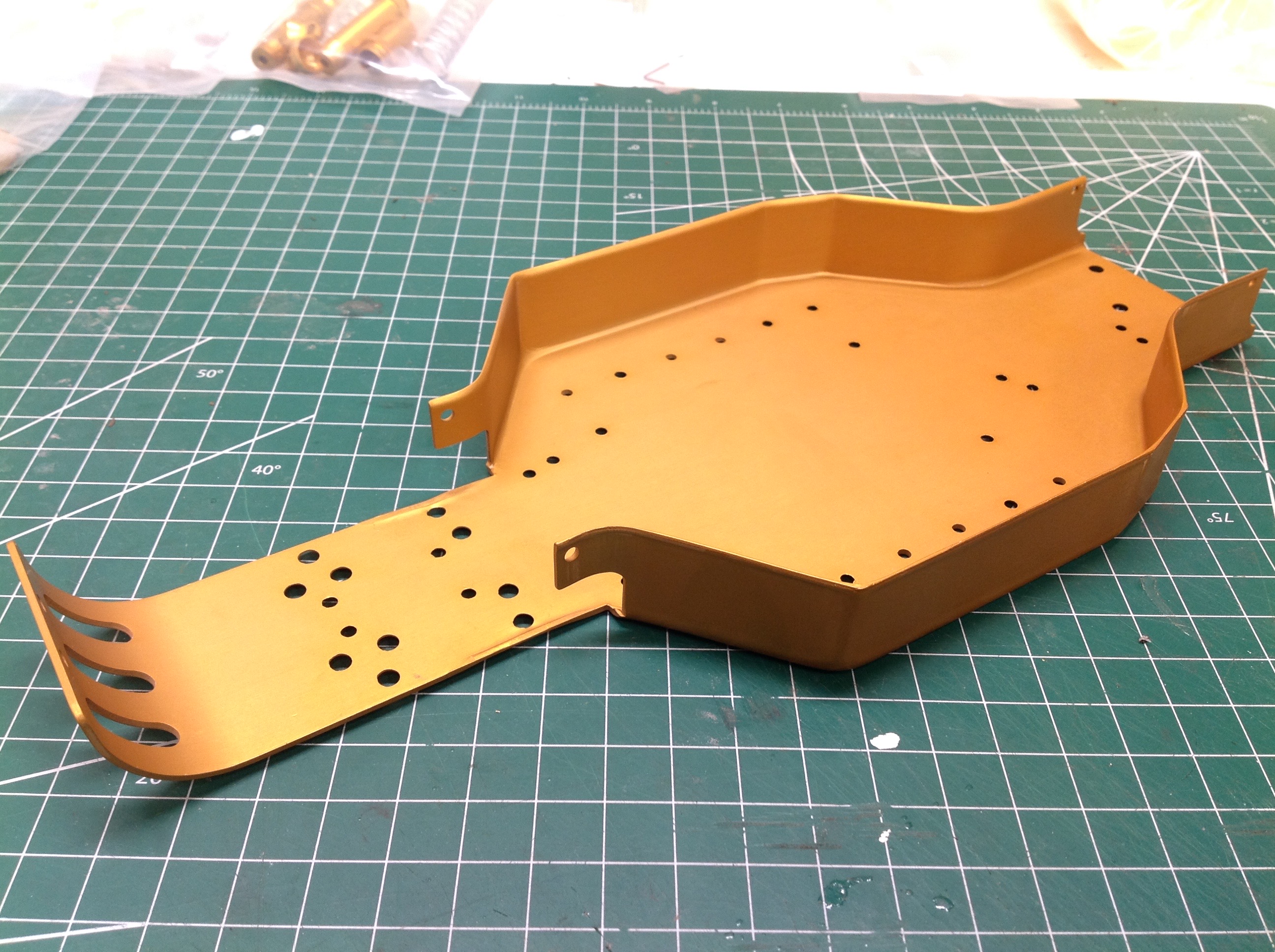
Construction begins with the aluminum chassis plate shown on the left
which appears to be formed from 0.063" sheet metal. The picture on
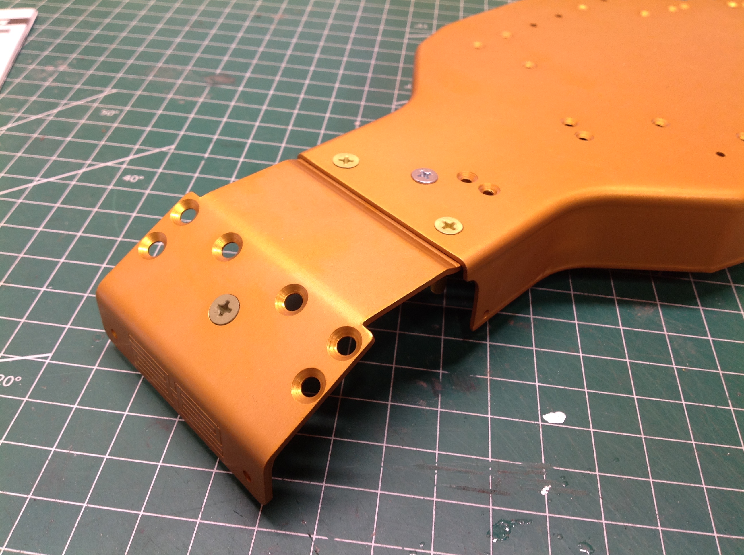
the right shows the attachment of the front chassis extension which
connects with very unusual 8-32 aluminum screws. For those
of you who are Imperial challenged, a #8 machine screw has a
nominal diameter 0.164" (~4.2mm) and these have a fine pitch of 32
threads per inch. Aluminum strips very easily so these need to be
installed with care. I can't think of a good reason to use
aluminum hardware here except to keep weight down.
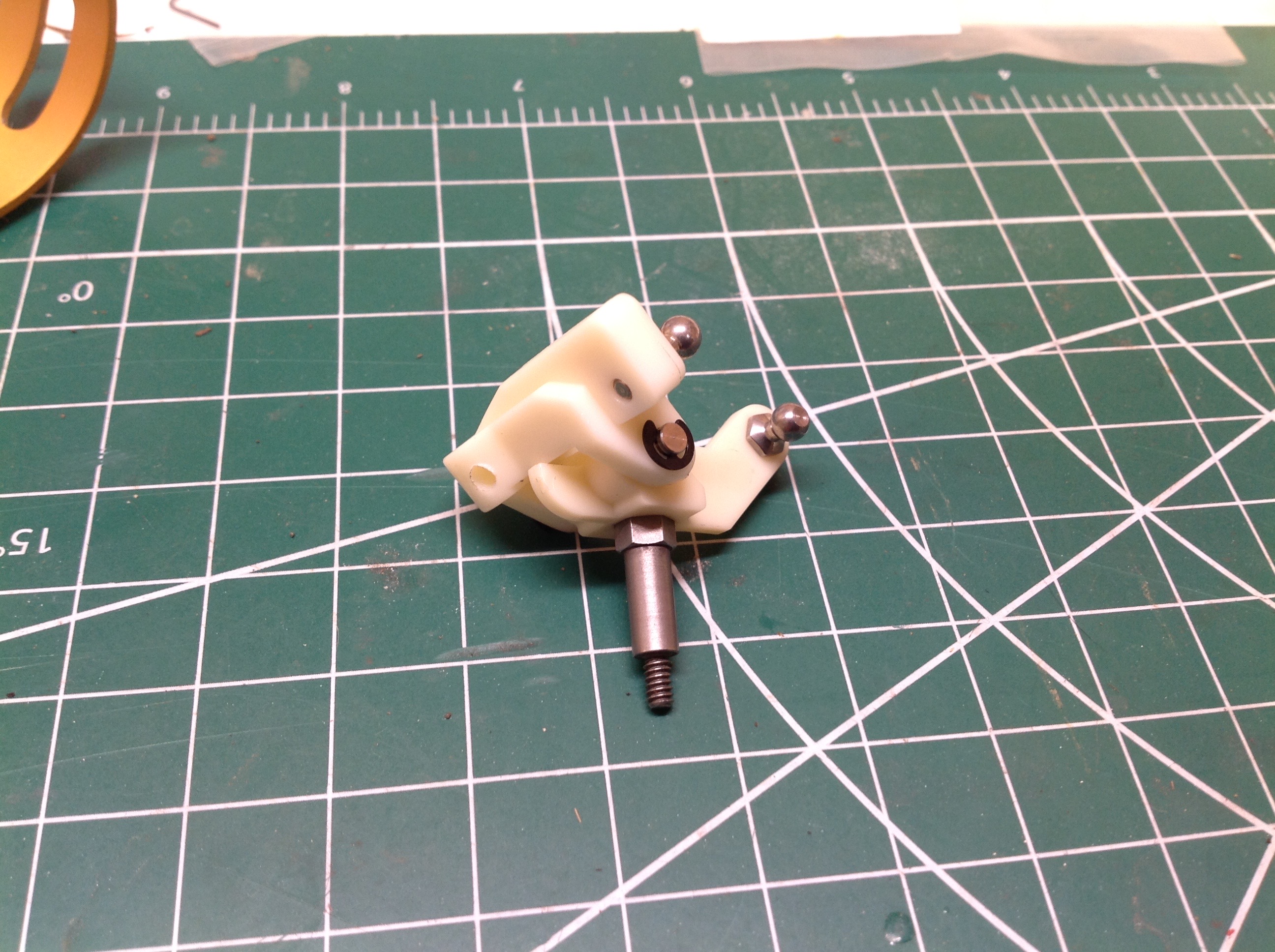
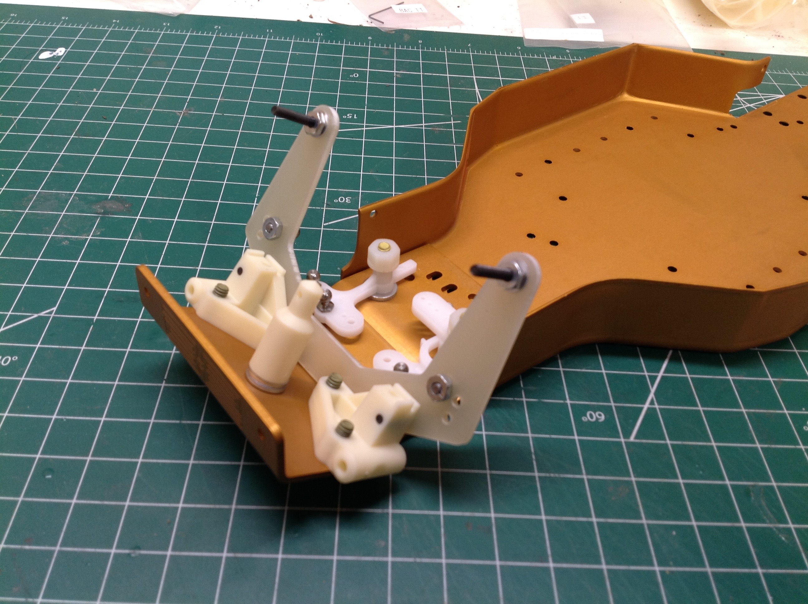
Let's get started on the front suspension. Nearly all of the
plastic parts in the model are polyamide 6/6 (Nylon) which has a creamy
white color but can be easily dyed to any other color. On the left
you can see the 15 degree caster block supporting the steering knuckle
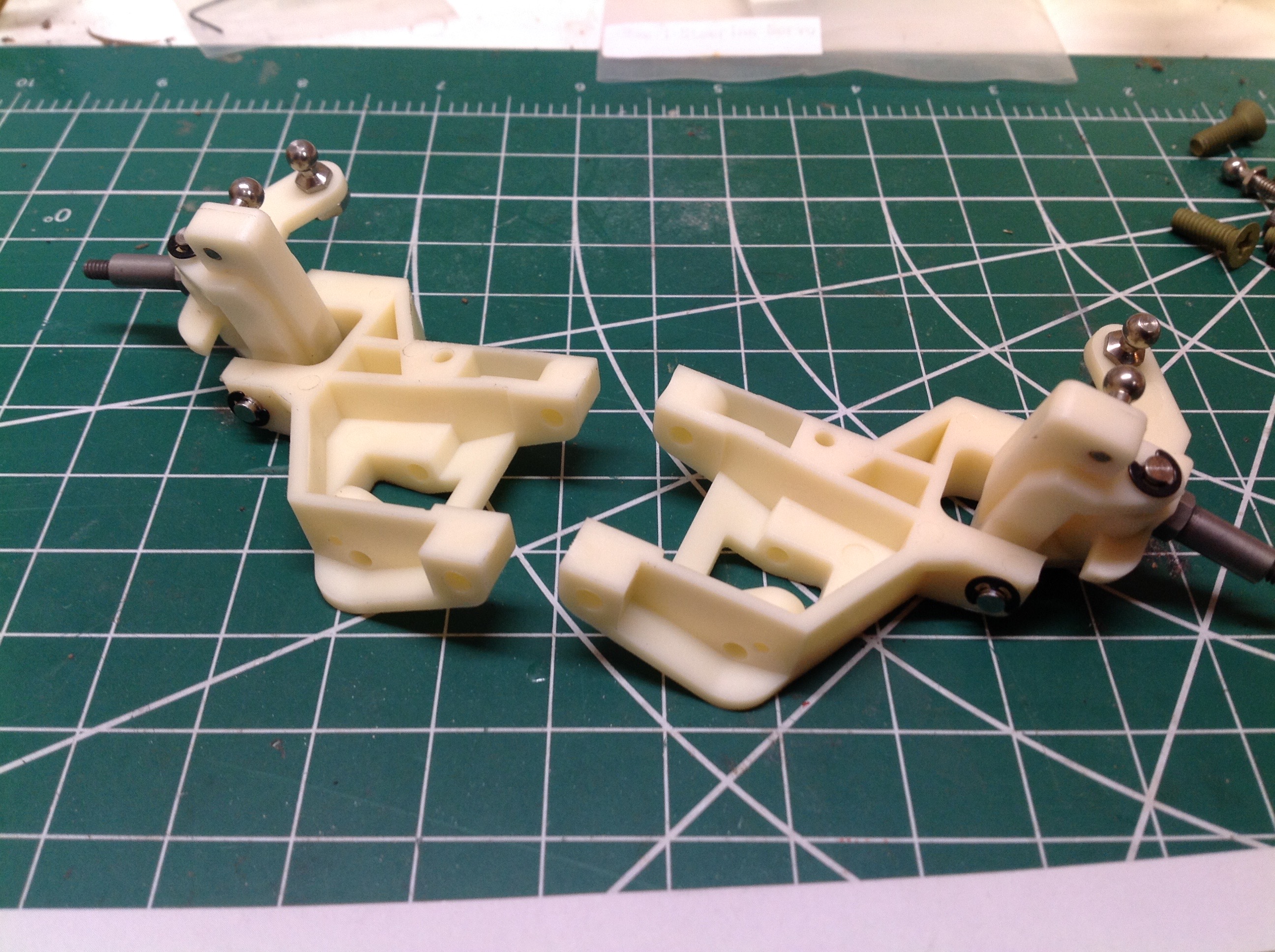
which is attached with a kingpin secured with E-clips at each end.
Imperial E-clips. Luckily they were close enough to a metric size
that I was able to install them with my usual 3mm tool. On the
right the steering uprights have been attached to the lower suspension
arms with longitudinal hinge pins.
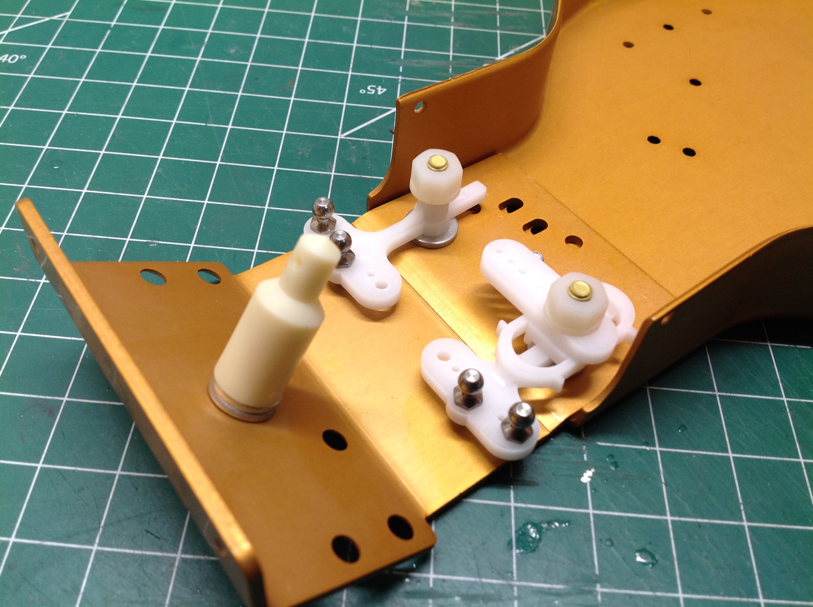
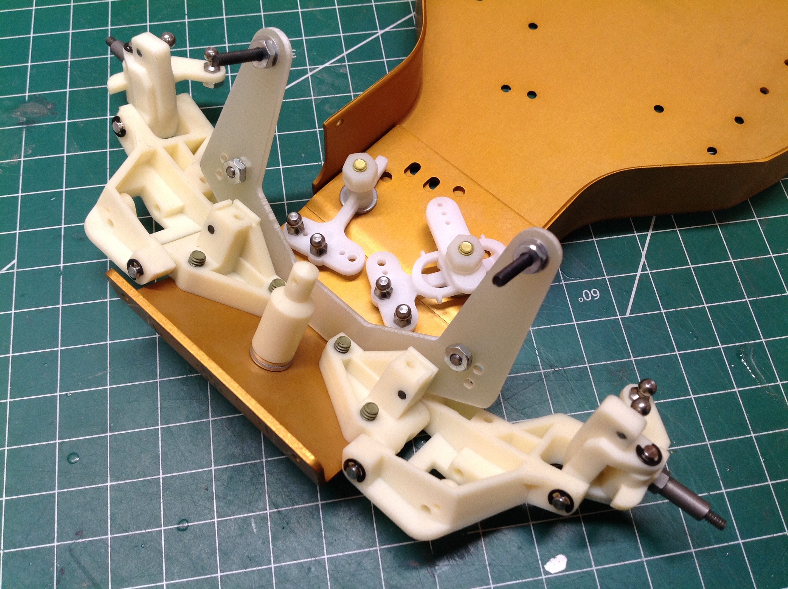
The left picture shows the steering cranks which pivot on shafts
attached to the chassis plate. They have no upper support.
The nuts are plastic to avoid over tightening and ensure free
motion. The servo saver works by deforming the oval slot in the
left hand crank. The right hand picture shows the front shock
tower which appears to be G10 fiberglass.
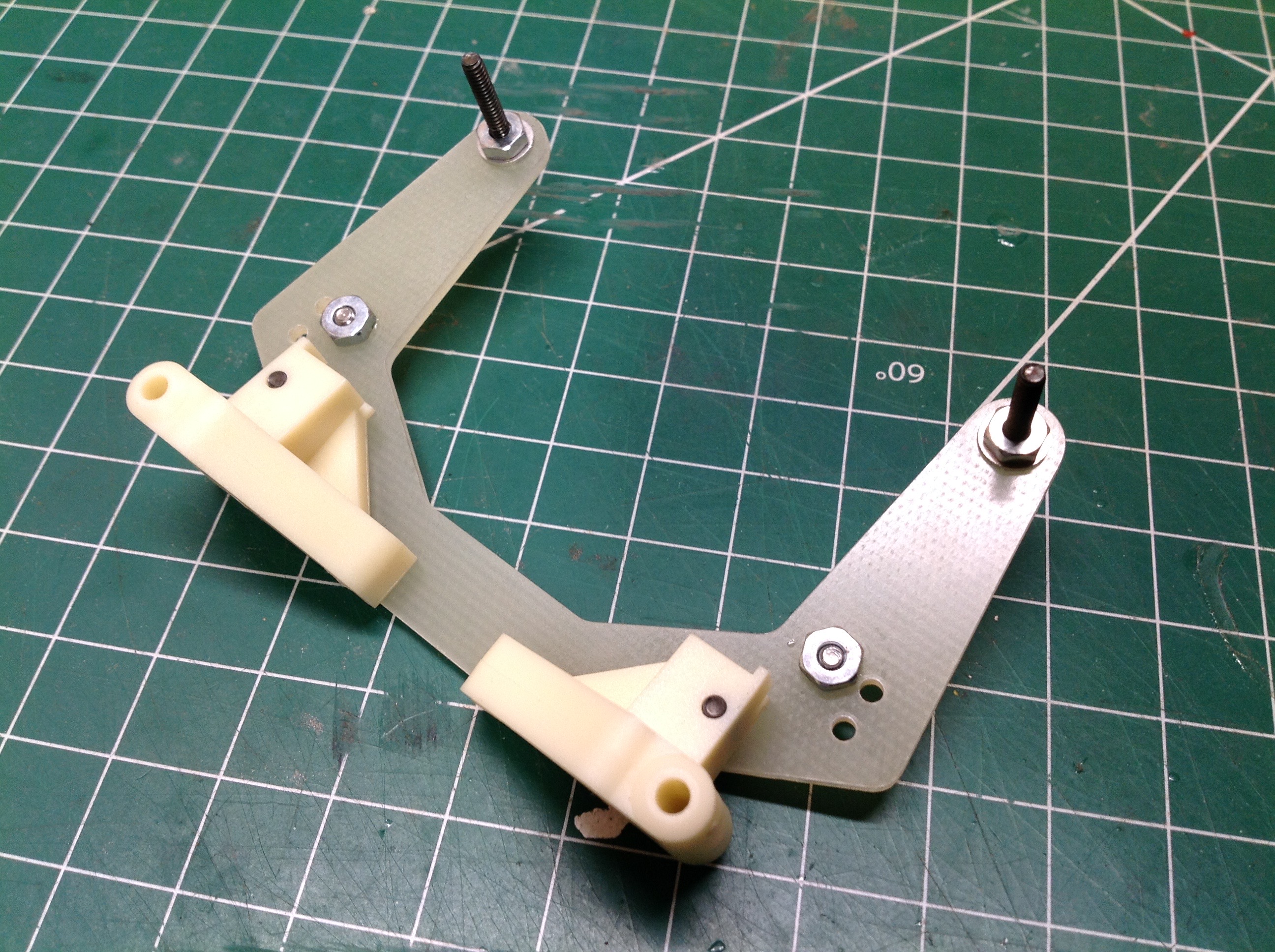
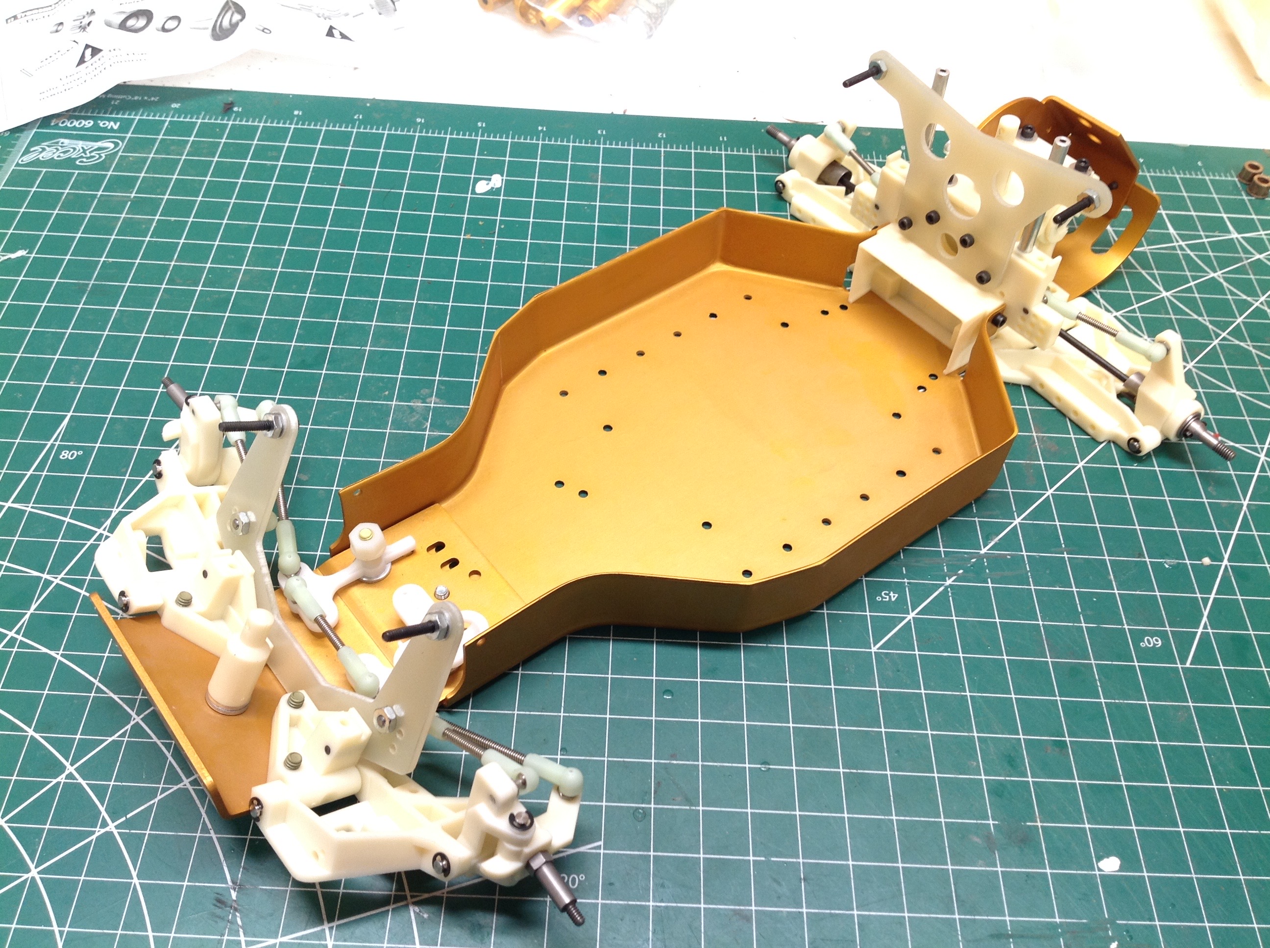
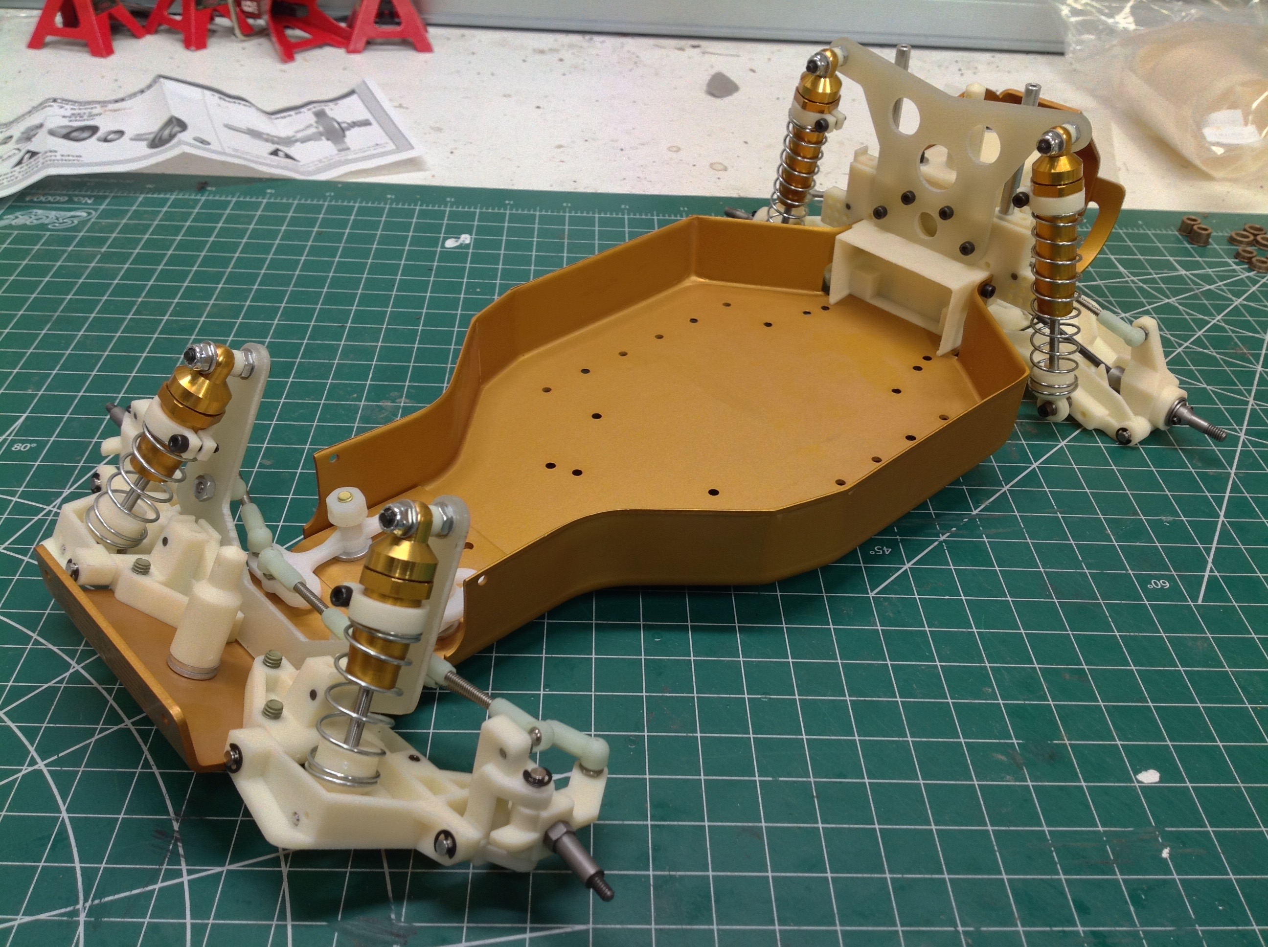
Now the previously built shock tower and front lower suspension modules
can be attached to the chassis plate as shown. Even though the
front suspension is not really complete, the assembly is halted at this
point so we can move on to the gearbox.
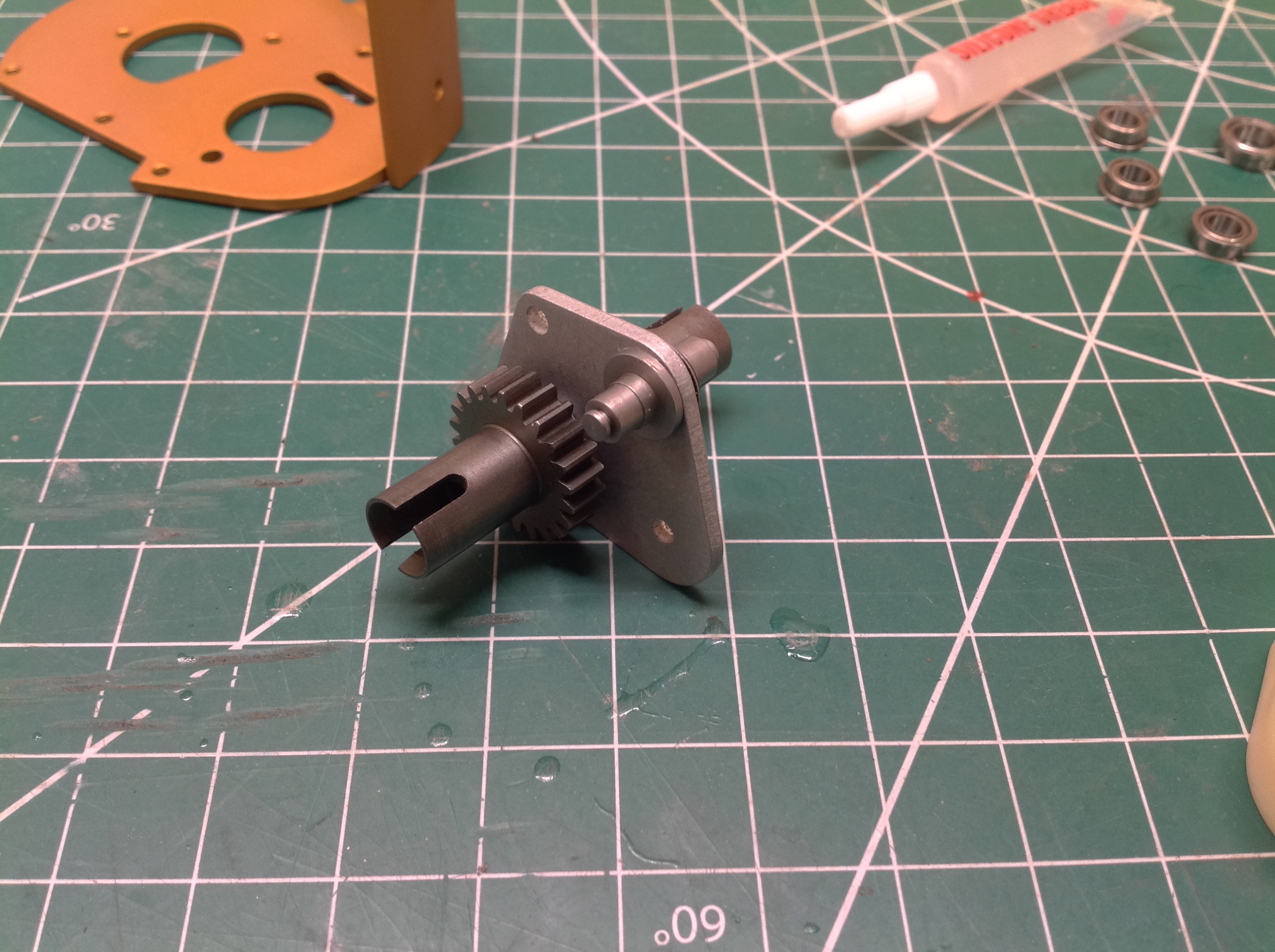
The gearbox is not quite like anything I've built before. We start
with the drive gear pin shown on the left. If you look closely,
you can see a roll pin which is inserted radially and fits into a slot
in the spine plate. On the right this has been installed along
with an idler gear pin.
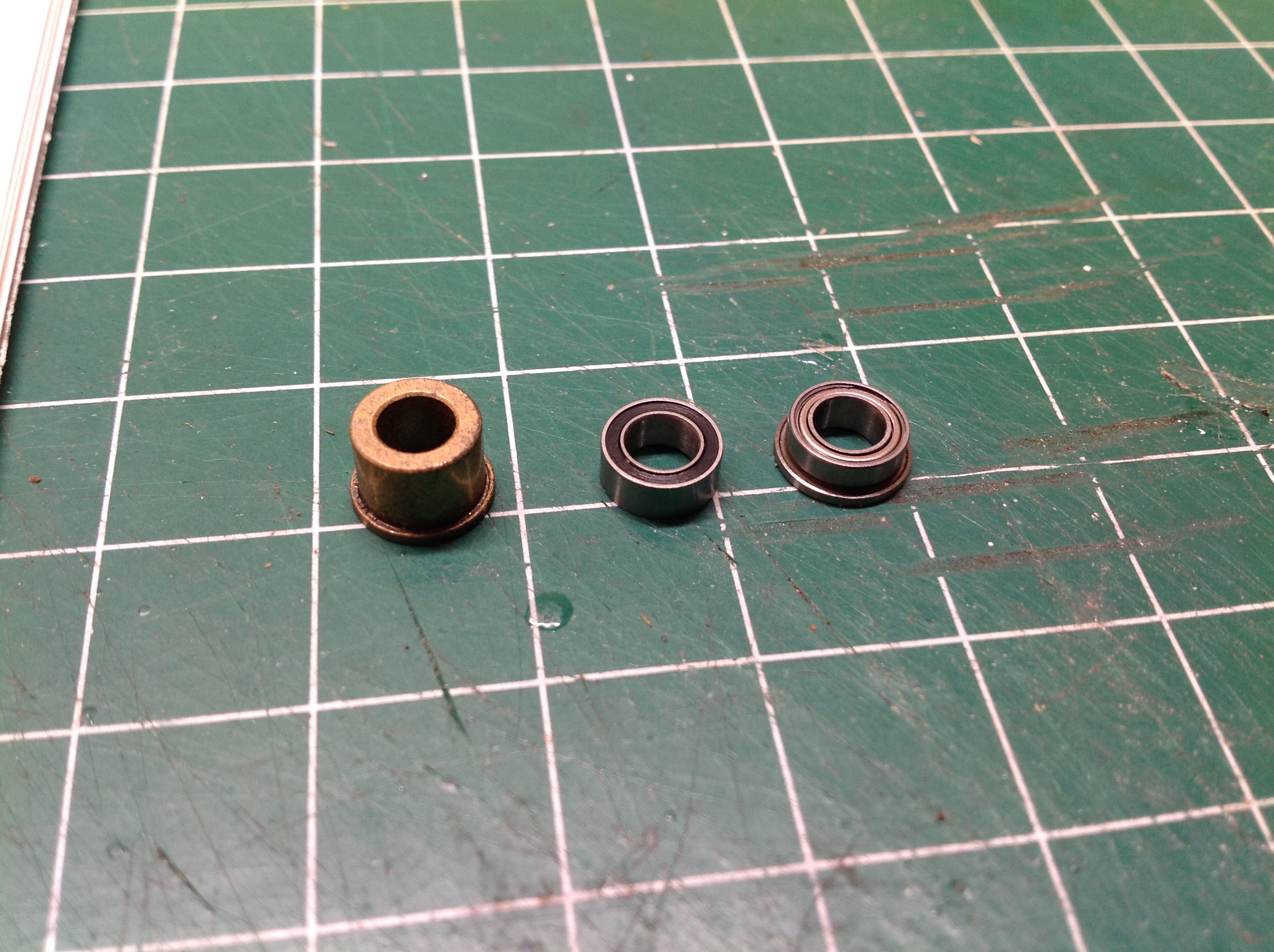
The kit comes with solid bushings rather than roller bearings so those
had to go. The wide flanged bushing shown at the left doesn't have
a direct roller replacement so a stack-up of two bearings is
substituted as shown. Again, these bearings use Imperial
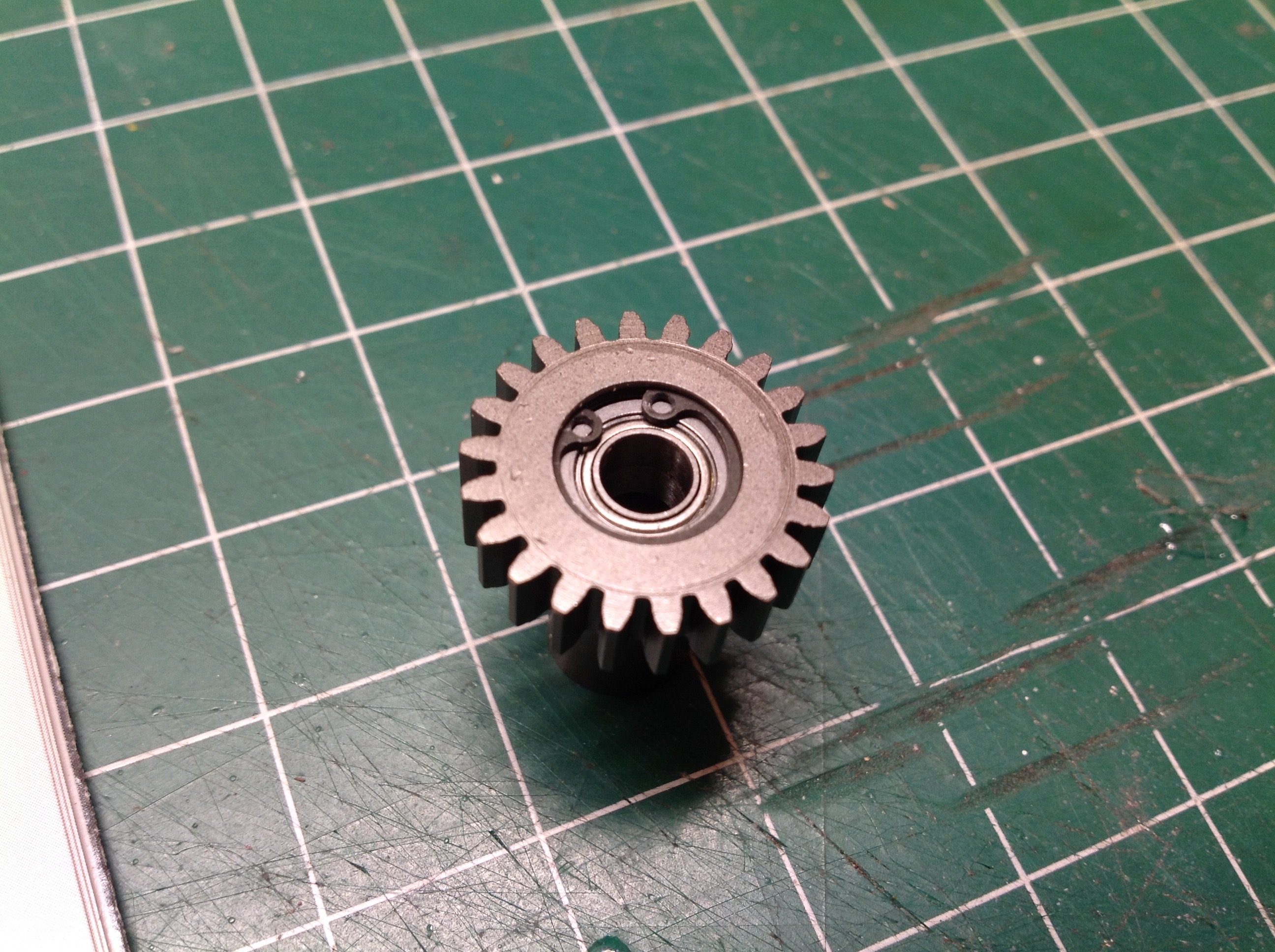
units. The bearings are installed in the steel drive gear using an
internal snap ring as shown. Good look installing it if you don't
have a dedicated snap ring pliers.
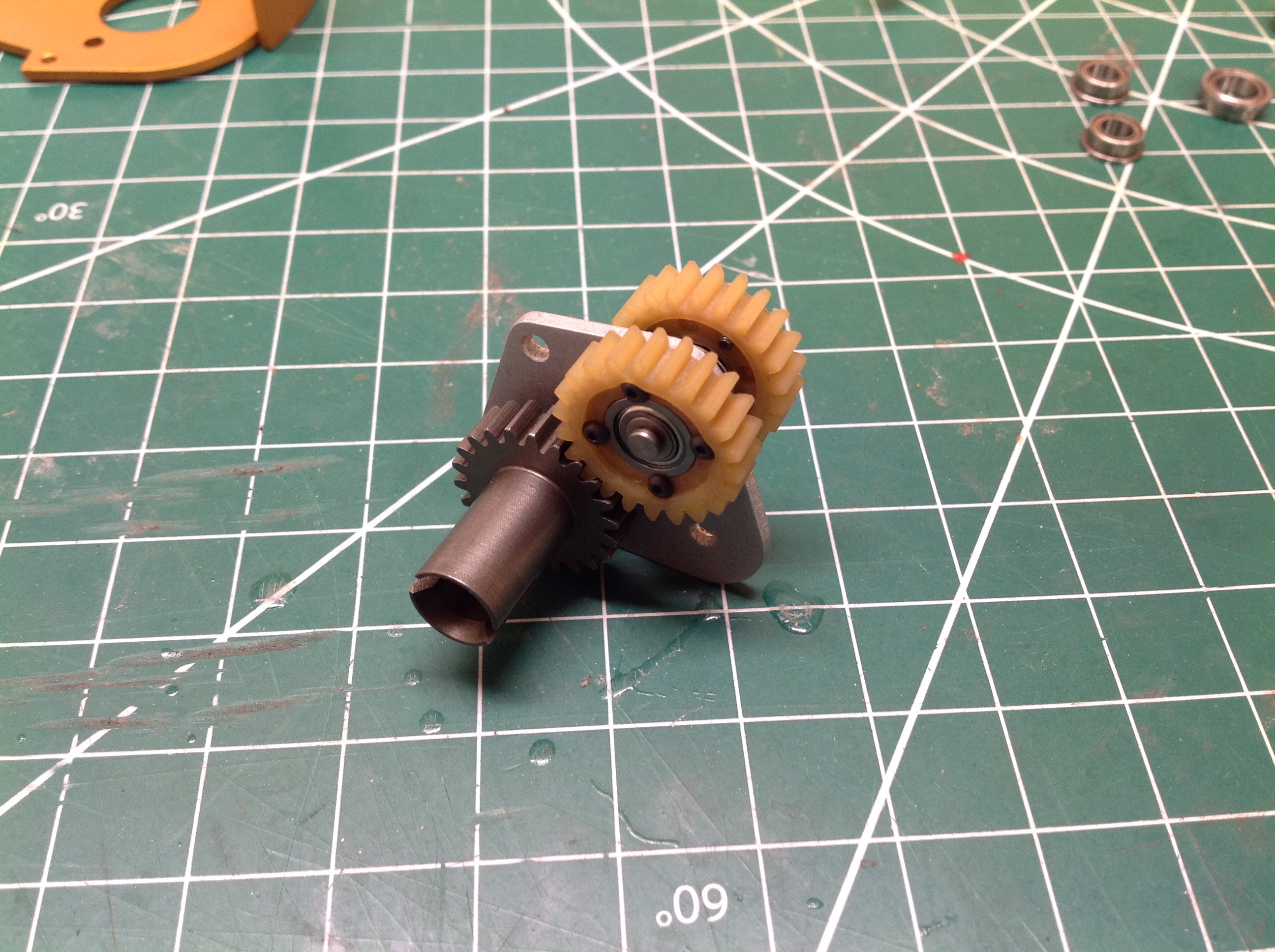
Two identical drive gears are built and then installed on opposite sides
on the spine plate as shown. The drive cups are integral to the
gears. The use of independent gears allows the two sides to rotate
at different speeds. These will need to be connected through a
differential.
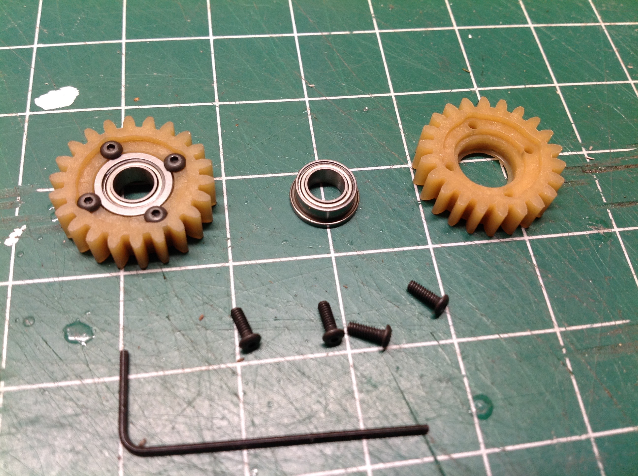
Next we build two independent idler gears using screws and flanged
bearings as shown. Every gear pair consists of one side metal and
one plastic which obviates the need for additional grease
lubrication. The color of these plastic gears leads me to suspect
that they may be oil impregnated for long life.
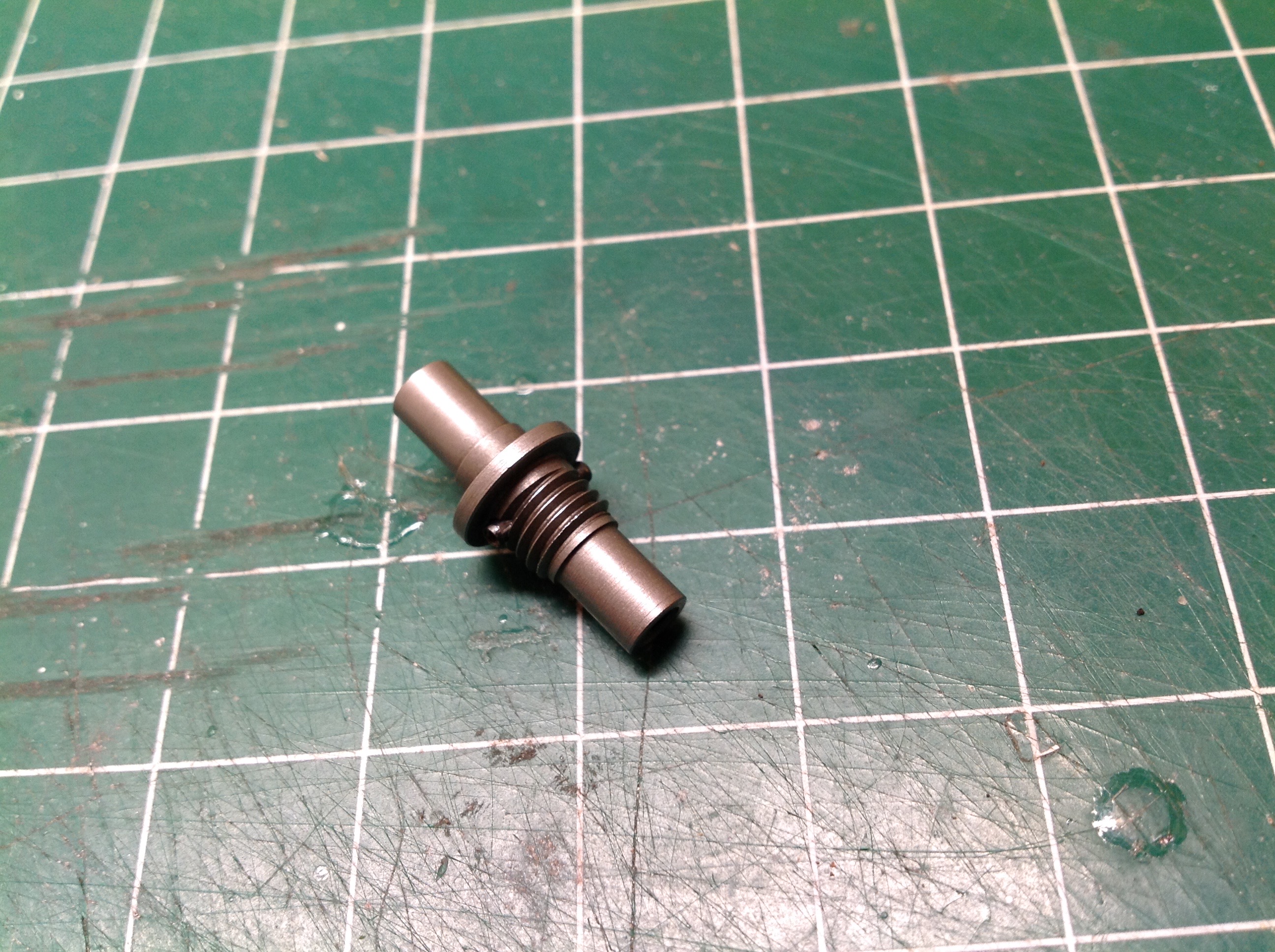
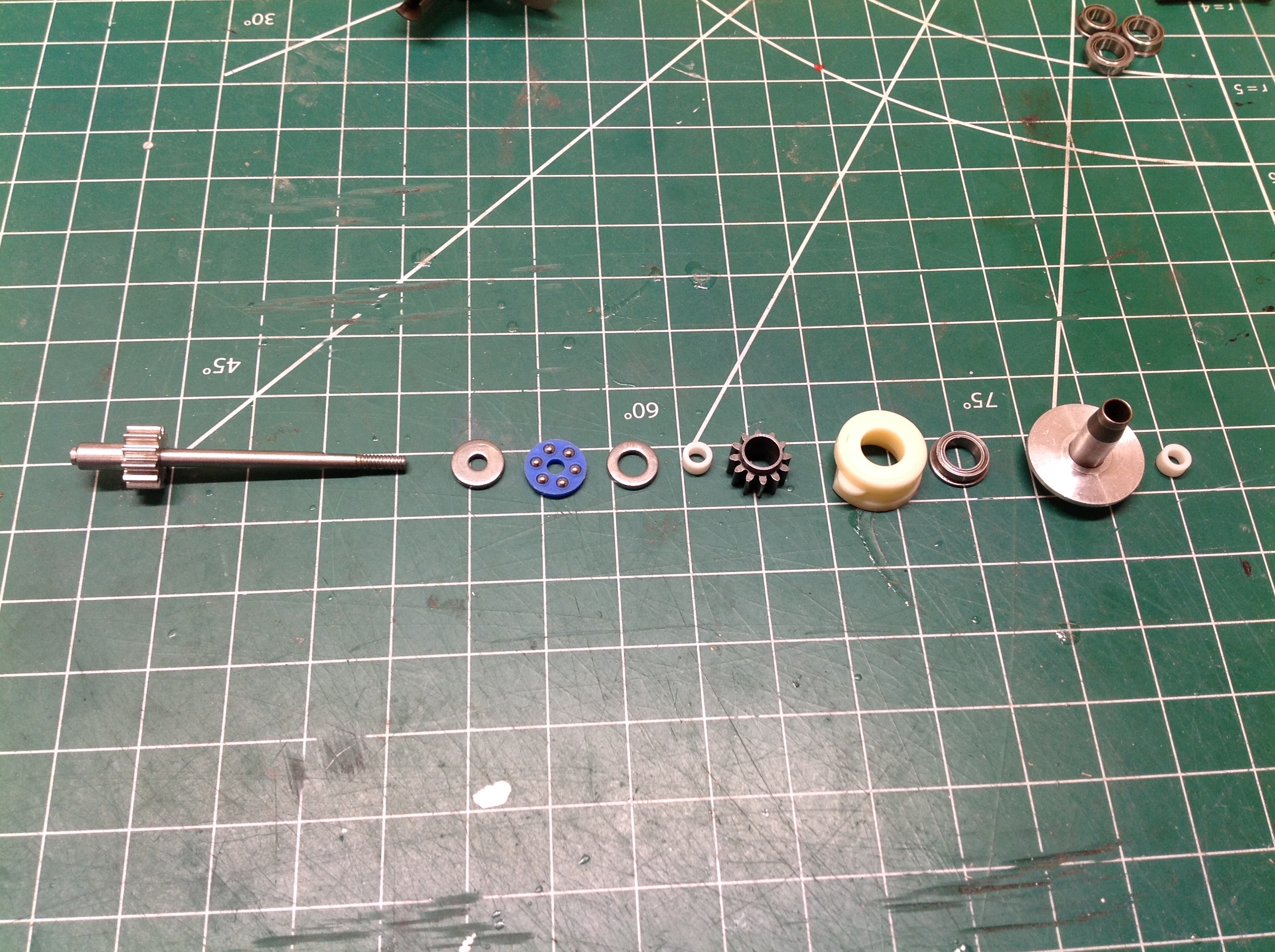
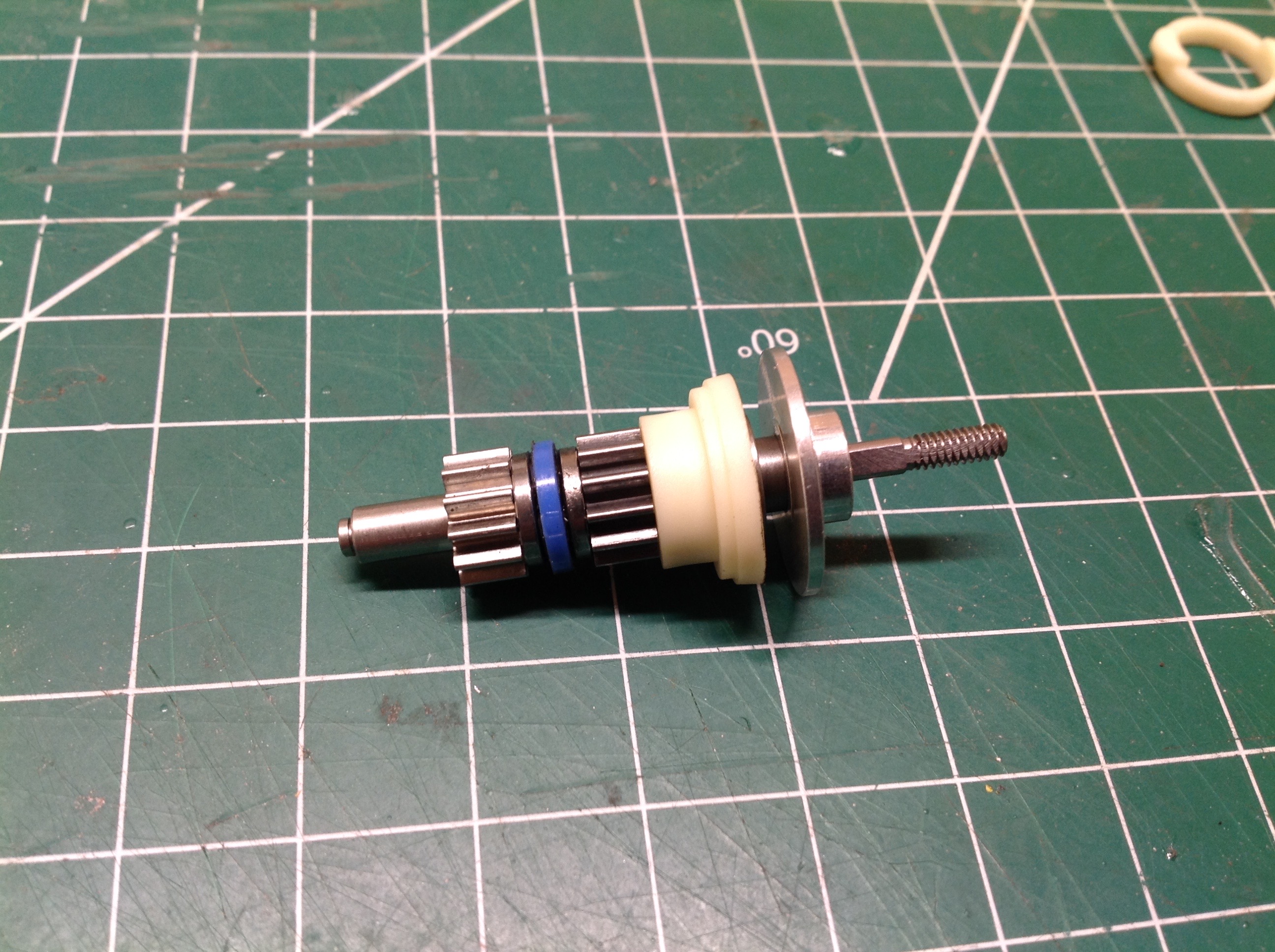
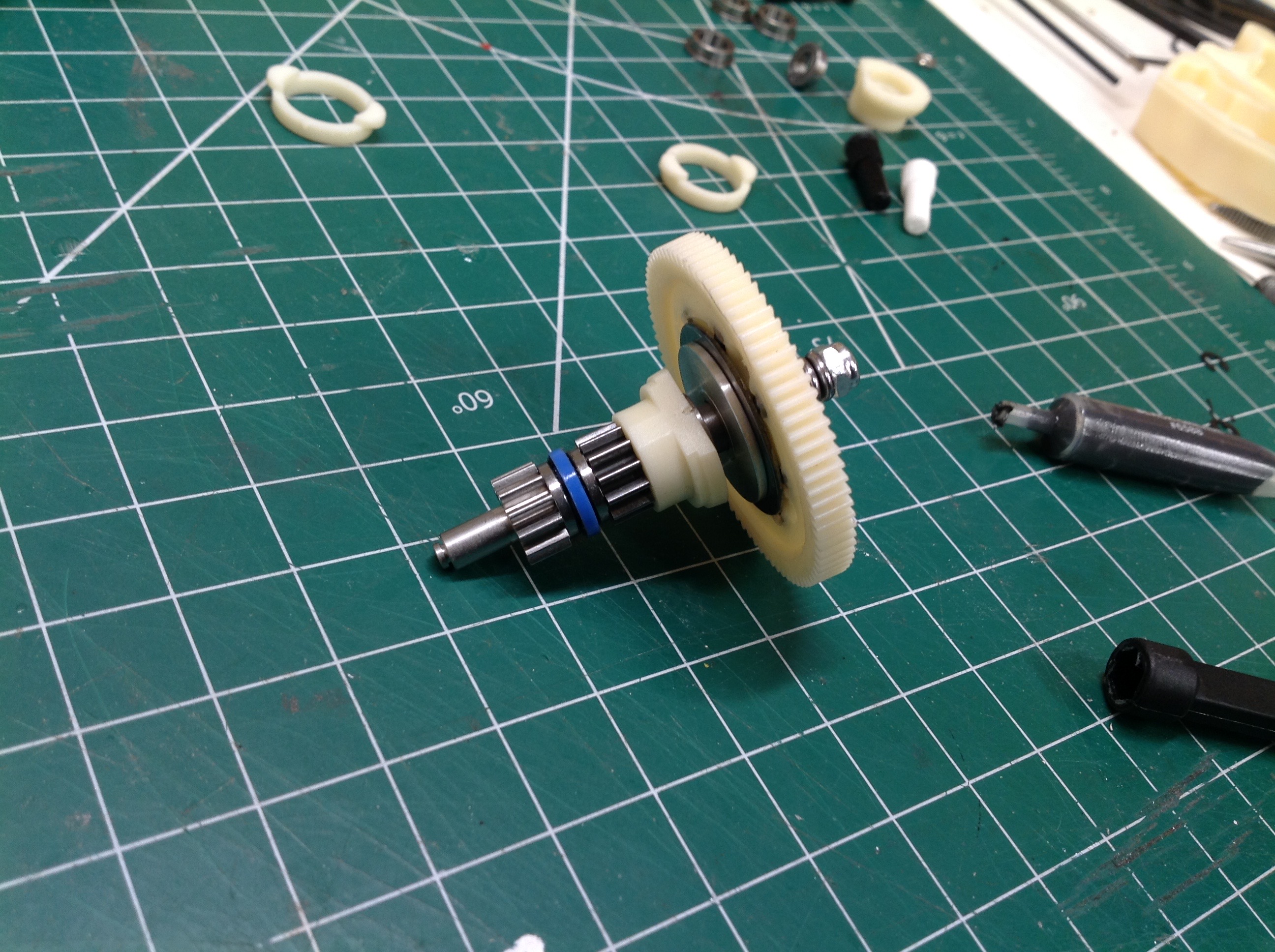
The ball differential will be built into the spur gear shaft. The
small pinion gear at the far left is locked to the shaft. The
spool on the far right of the same image has a tapered end which is
pressed into the other pinion gear. On the right the two drive
pinions are assembled together on the shaft with a thrust bearing
between them. This allows them to be clamped together tightly but
still rotate independently.
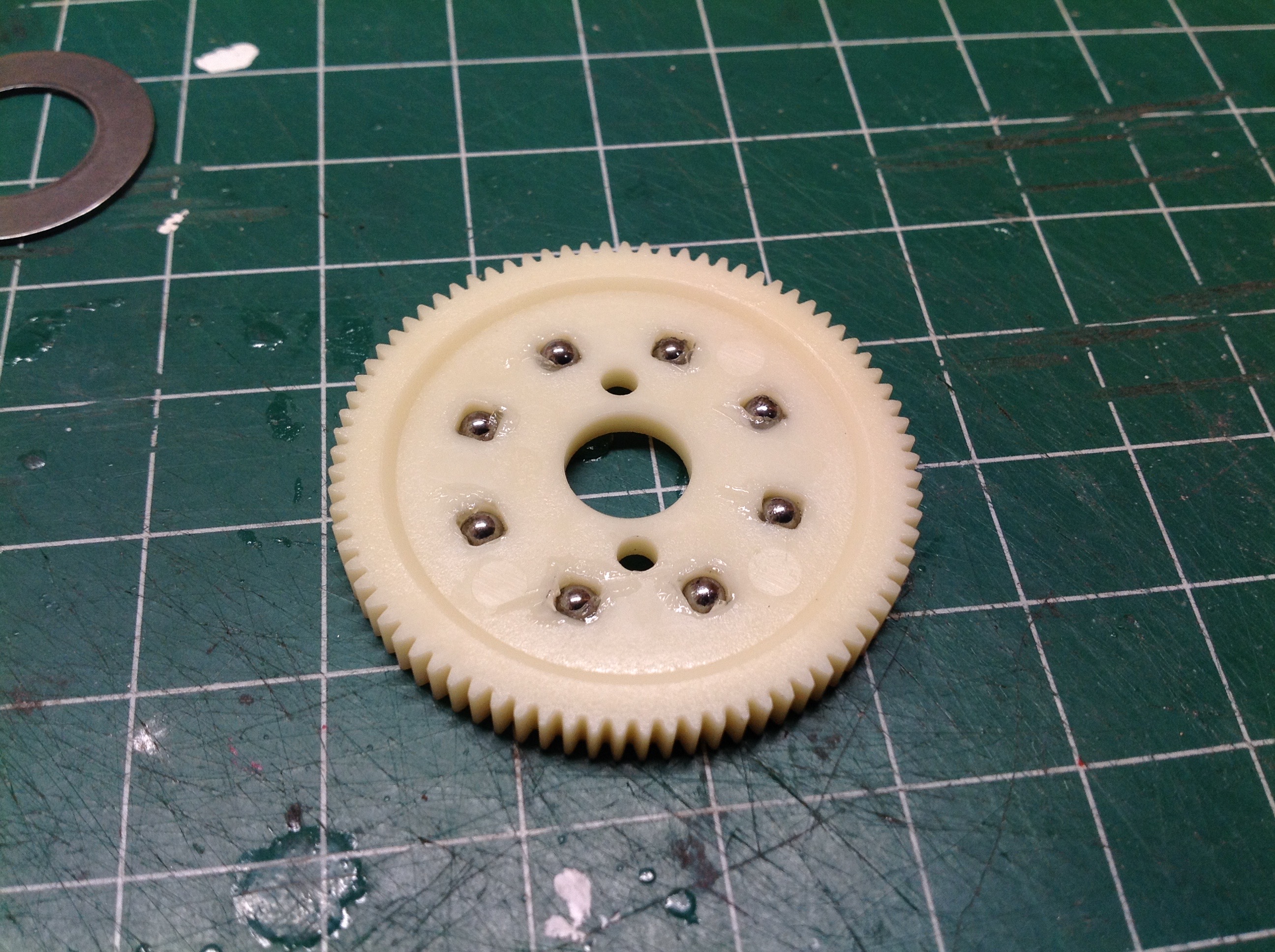
The 1/8" balls for the differential are inserted into the 81T spur gear
as shown. Once the assembly is greased, hardened drive rings are
installed on either side and then the whole thing is clamped on the diff
shaft using a compression spring as shown.
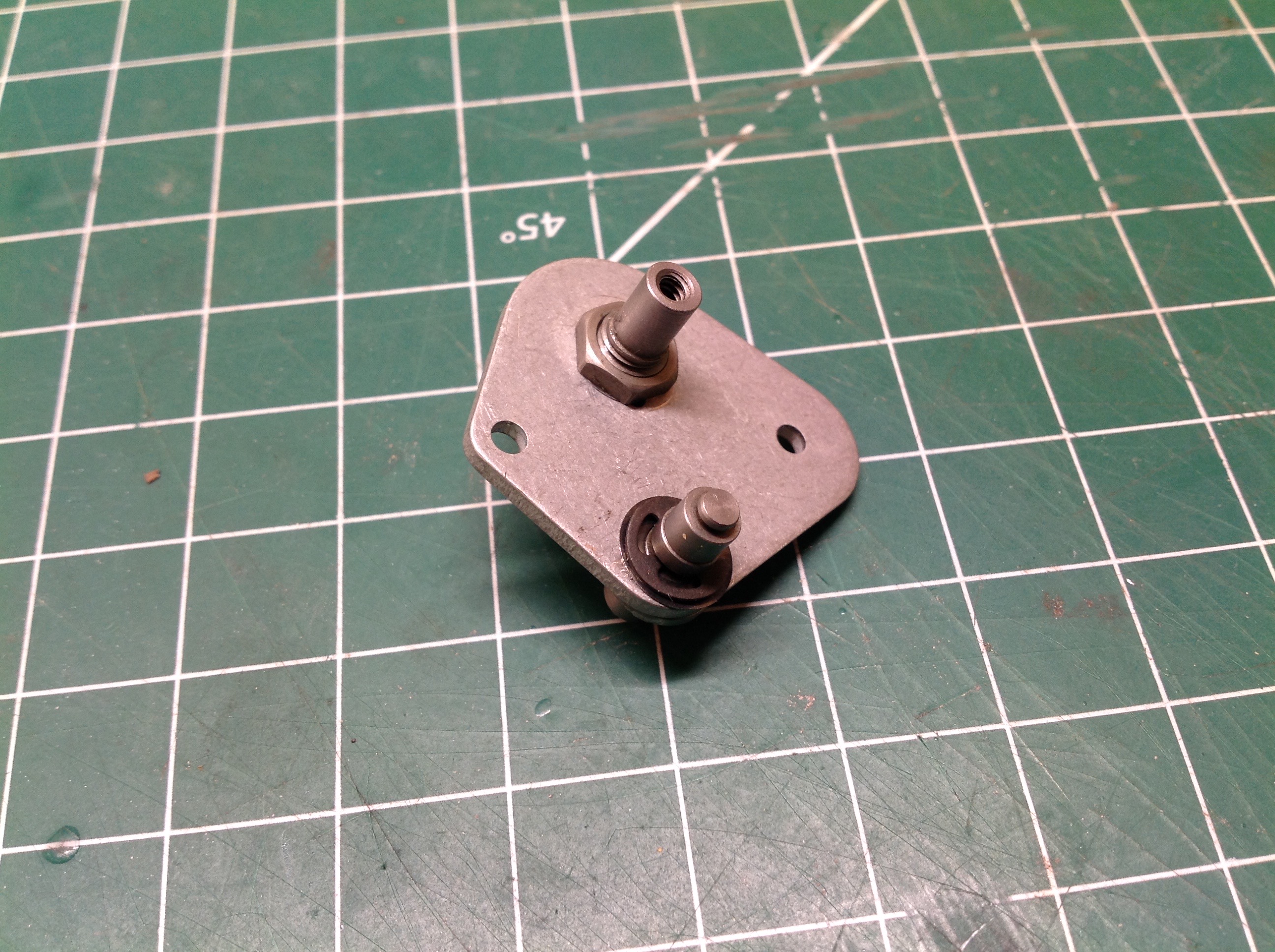
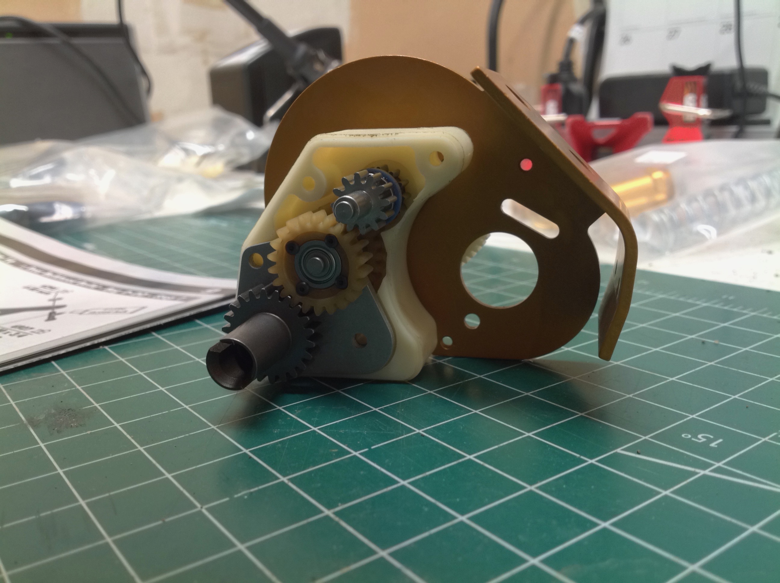
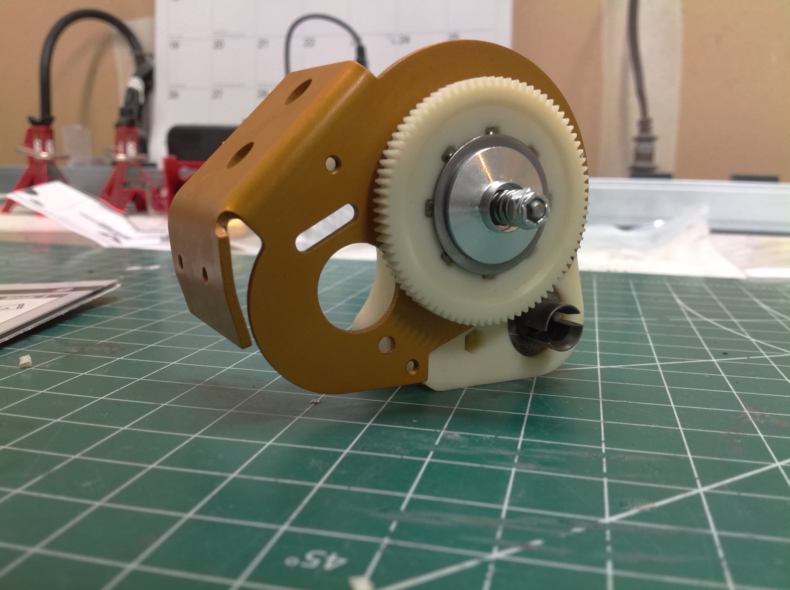
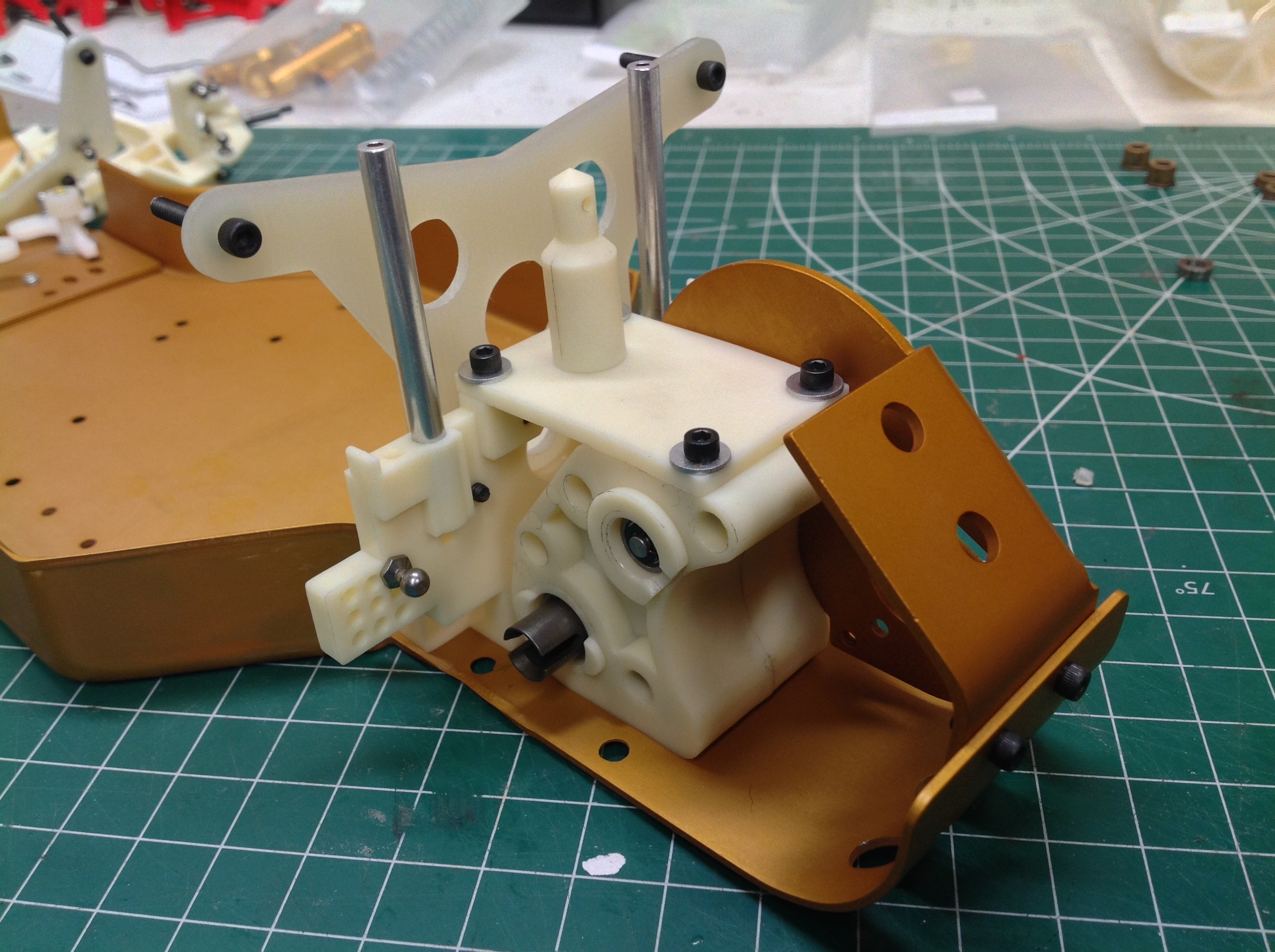
Now the transmission housing can be attached to the motor plate with the
spine plate as shown on the left. There are 3 gears on the left
and 3 gears on the right of the transmission, connected only through the
ball differential. The diff adjustment screw is seen from the
other side on the right.
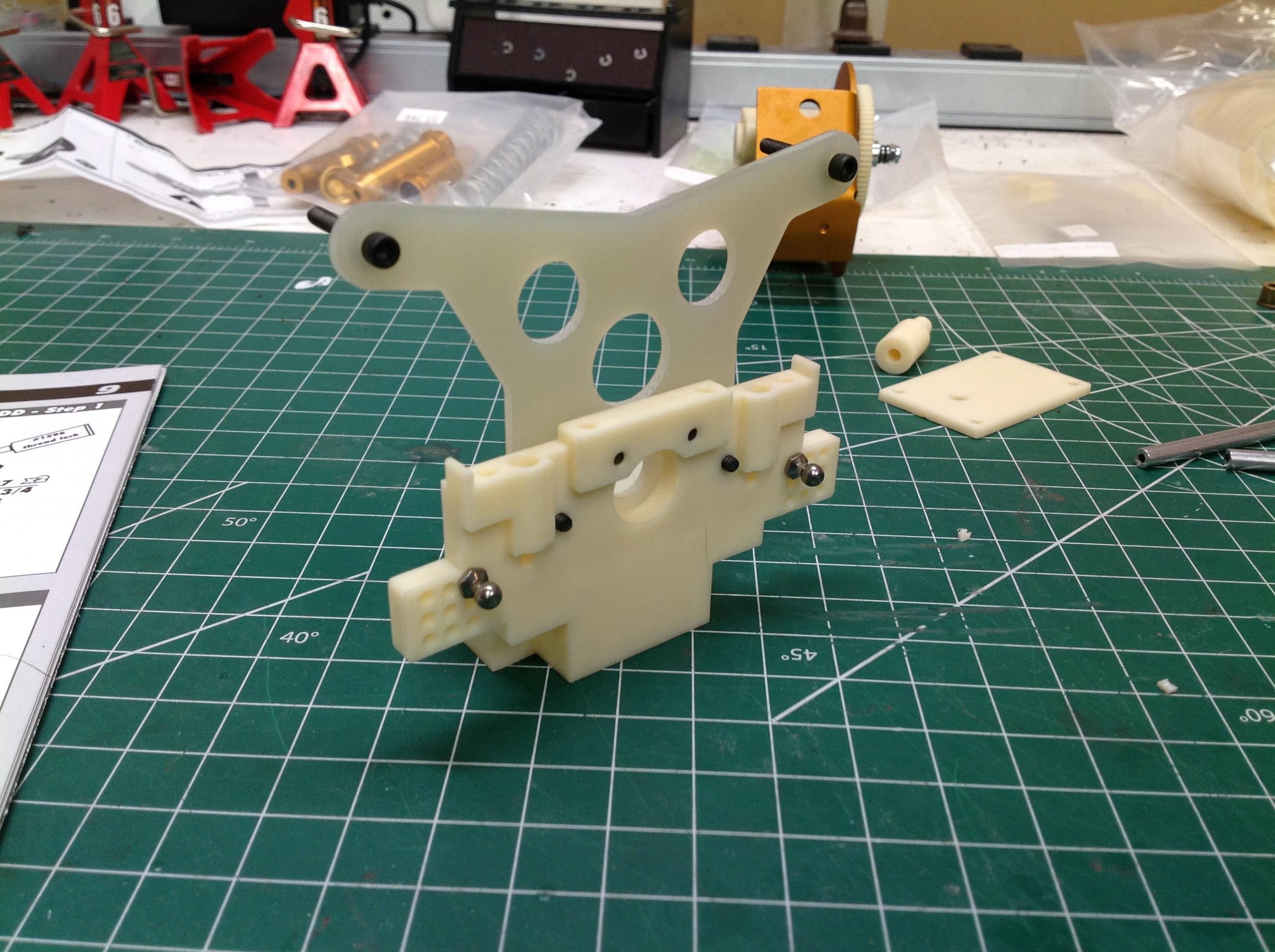
A large rear bulkhead is used to attach the shock tower as well as
support the installation of the gearbox as shown. Note the 9
different holes available for the ball joint which will support the
upper suspension arm. The upper-inner position is used by
default. Though you can't see it in the picture, each drive cup is
surrounded by a felt seal to keep out dust and debris which is then
captured with a plastic retainer.
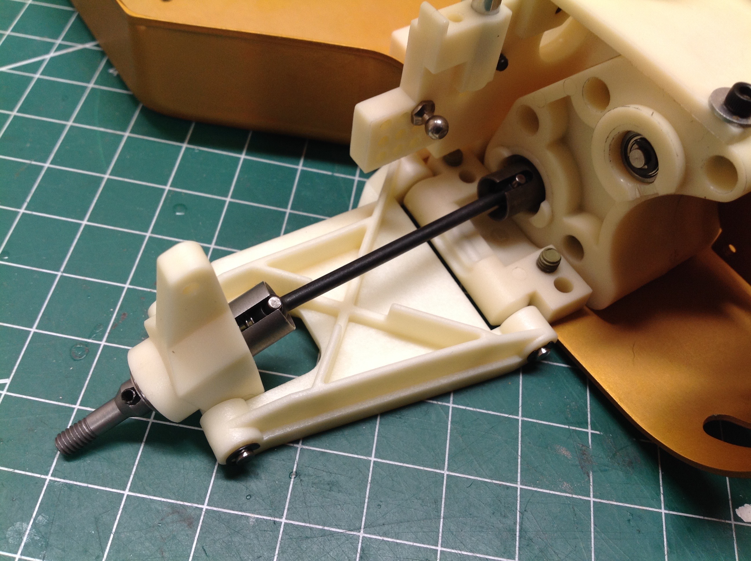
Now the lower rear suspension arm are installed along with the upright
hubs. Standard dog bones are used as drive axles. The upper
suspension arms are called "turnbuckles" in the instructions but they
are not true turnbuckles (which have a reverse thread on one end), they
are just threaded rods. This means they must be disconnected to be
adjusted. The camber can be adjusted by changing the length of
the links, and the inboard position of each link attachment can also be
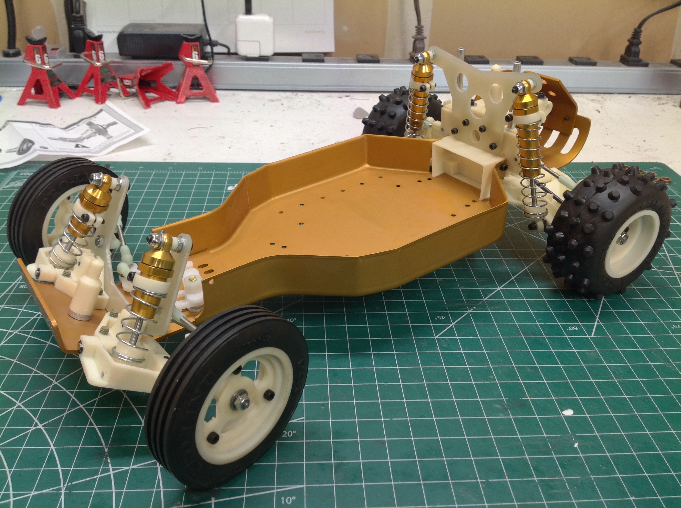
moved to multiple possible locations. We've now completed the
suspension assemblies at all four corners of the chassis. The
rectangular slot just ahead of the rear suspension is used to center the
battery.
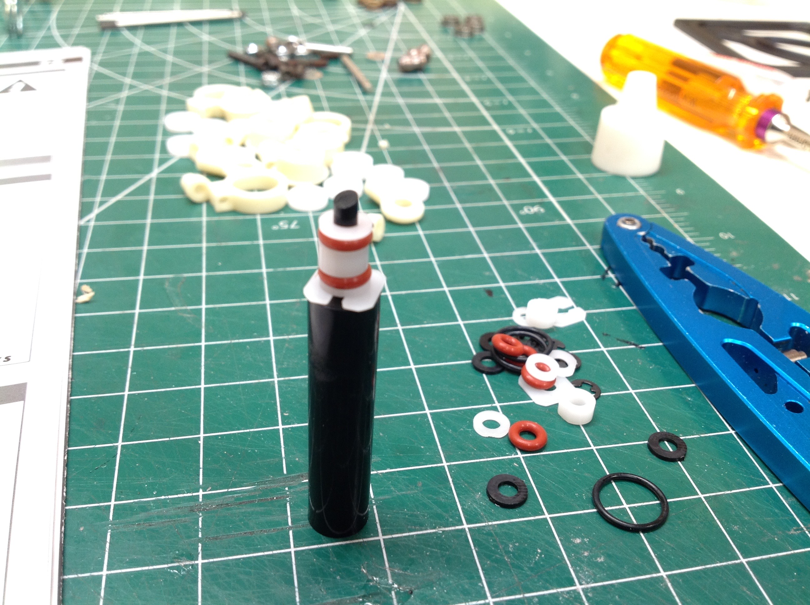
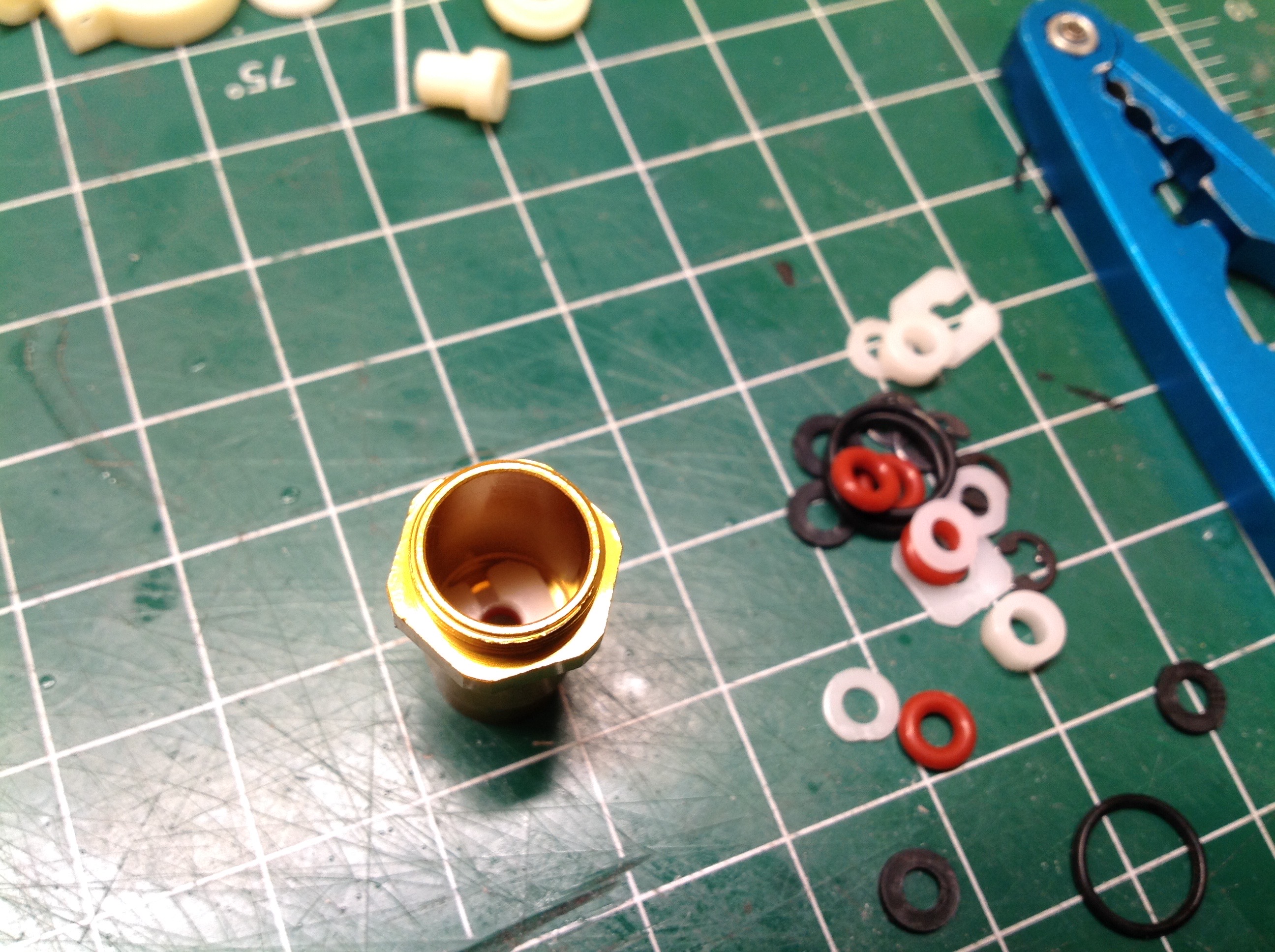
While the aluminum shocks may look conventional from the outside, the
assembly method is quite unusual. The rod end of the cylinder does
not have a cap for encasing the seals. Instead, the seals insert
from the head end. We start by assembling the a stack of two
o-ring seals, a rod guide, some spacers, and a square retainer clip on
the included tool as shown on the left. Using this tool, the whole
stock is inserted into the cylinder until it snaps into place as shown
on the right. Removing these parts for repair would be quite
difficult.
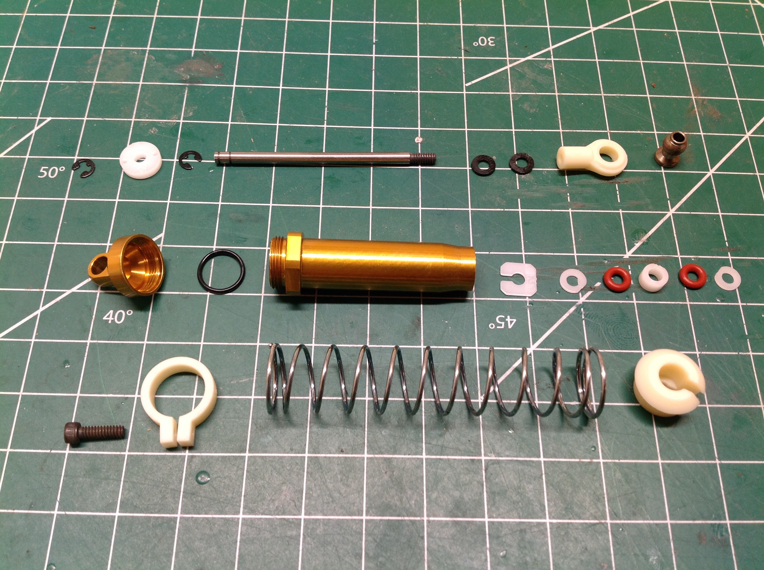
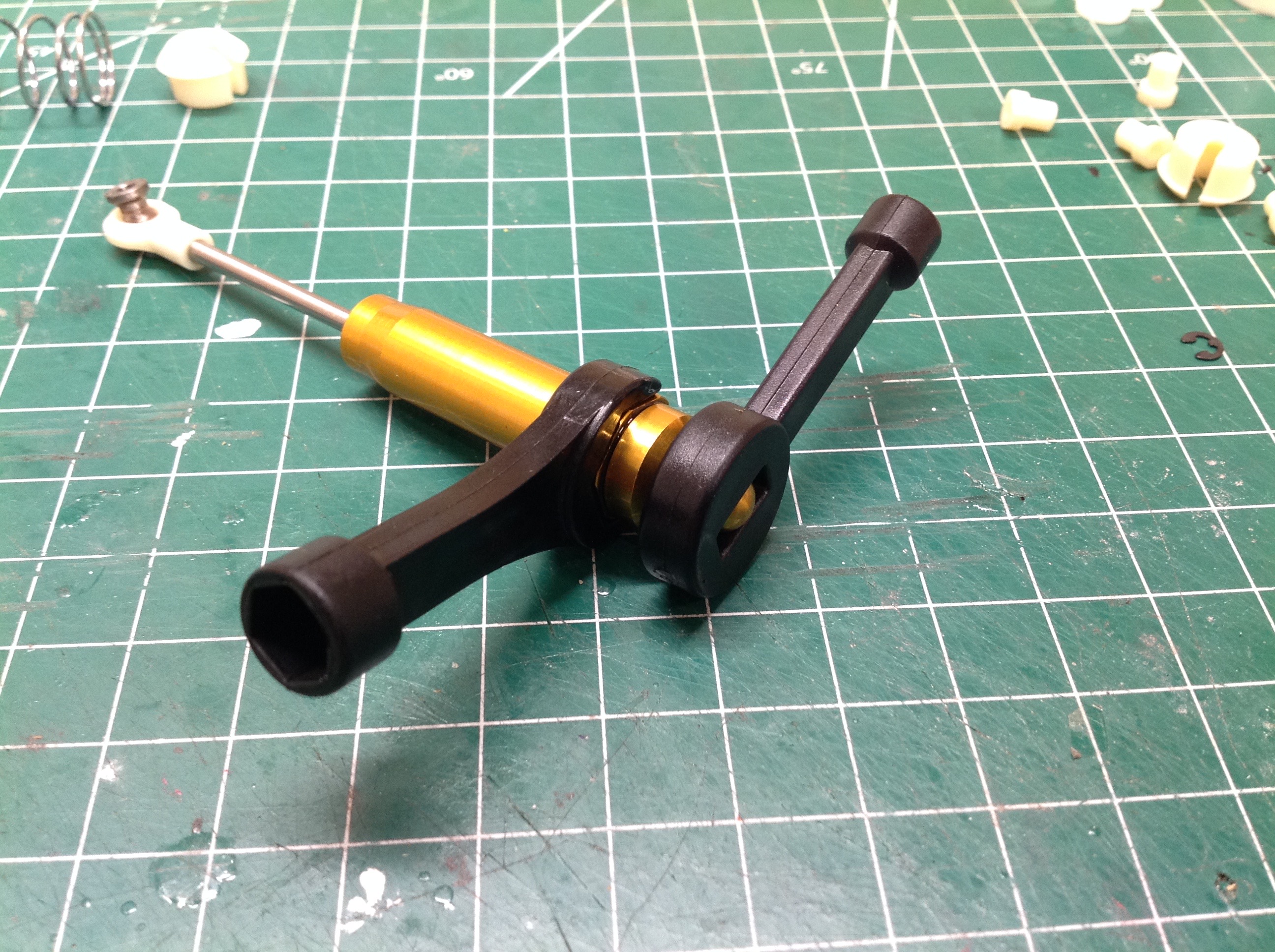
The picture on the left shows a complete exploded view of an entire rear
shock assembly. The picture on the right shows how a pair of
plastic tools included in the kit are used to tighten the head end cap.
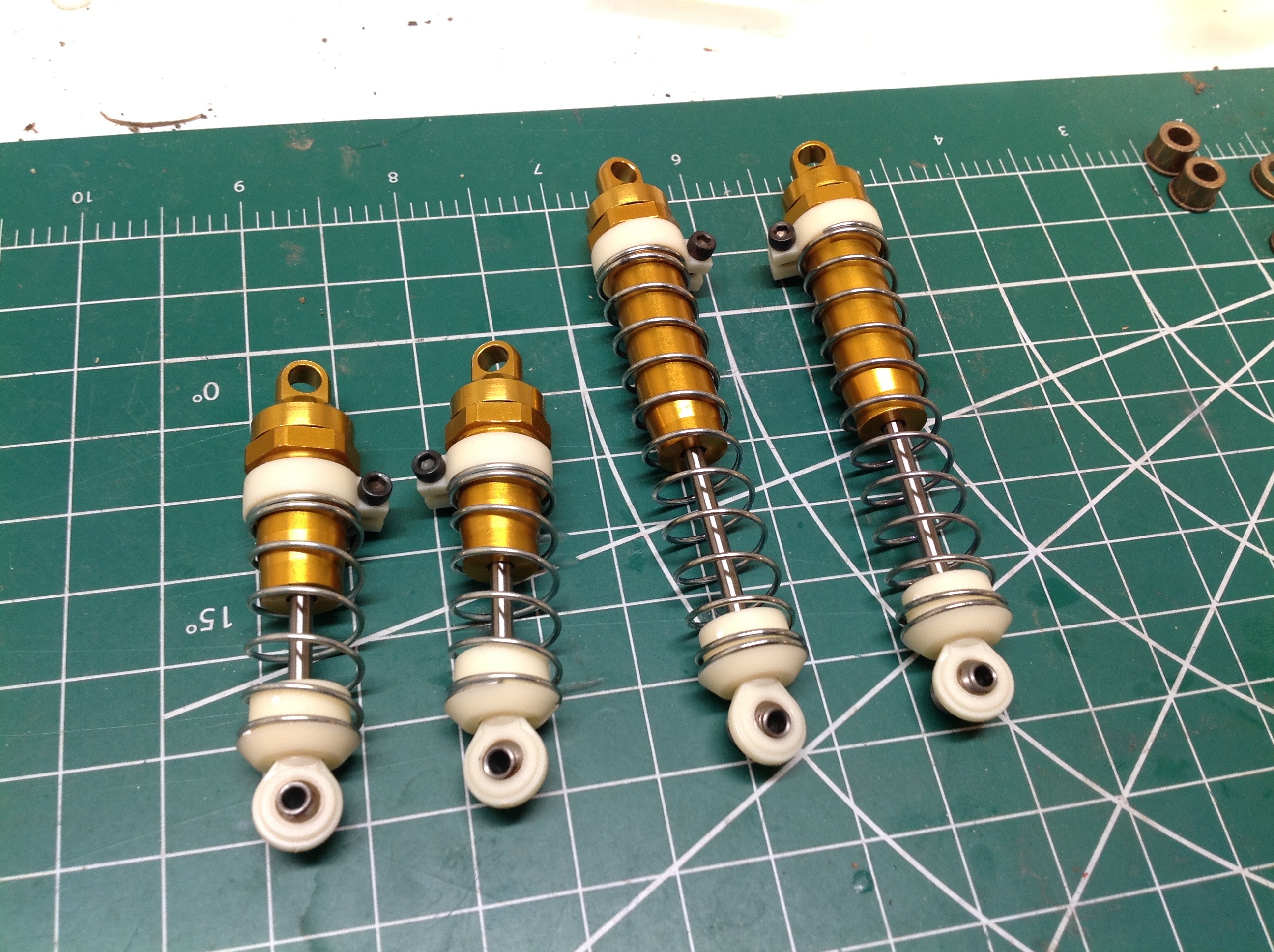
The completed front and rear shocks are shown on the left. The
upper spring guides are not threaded to the shock cylinder.
Instead, they are just clamped in place with a cap screw and held with
friction. The completed installation is shown on the right.
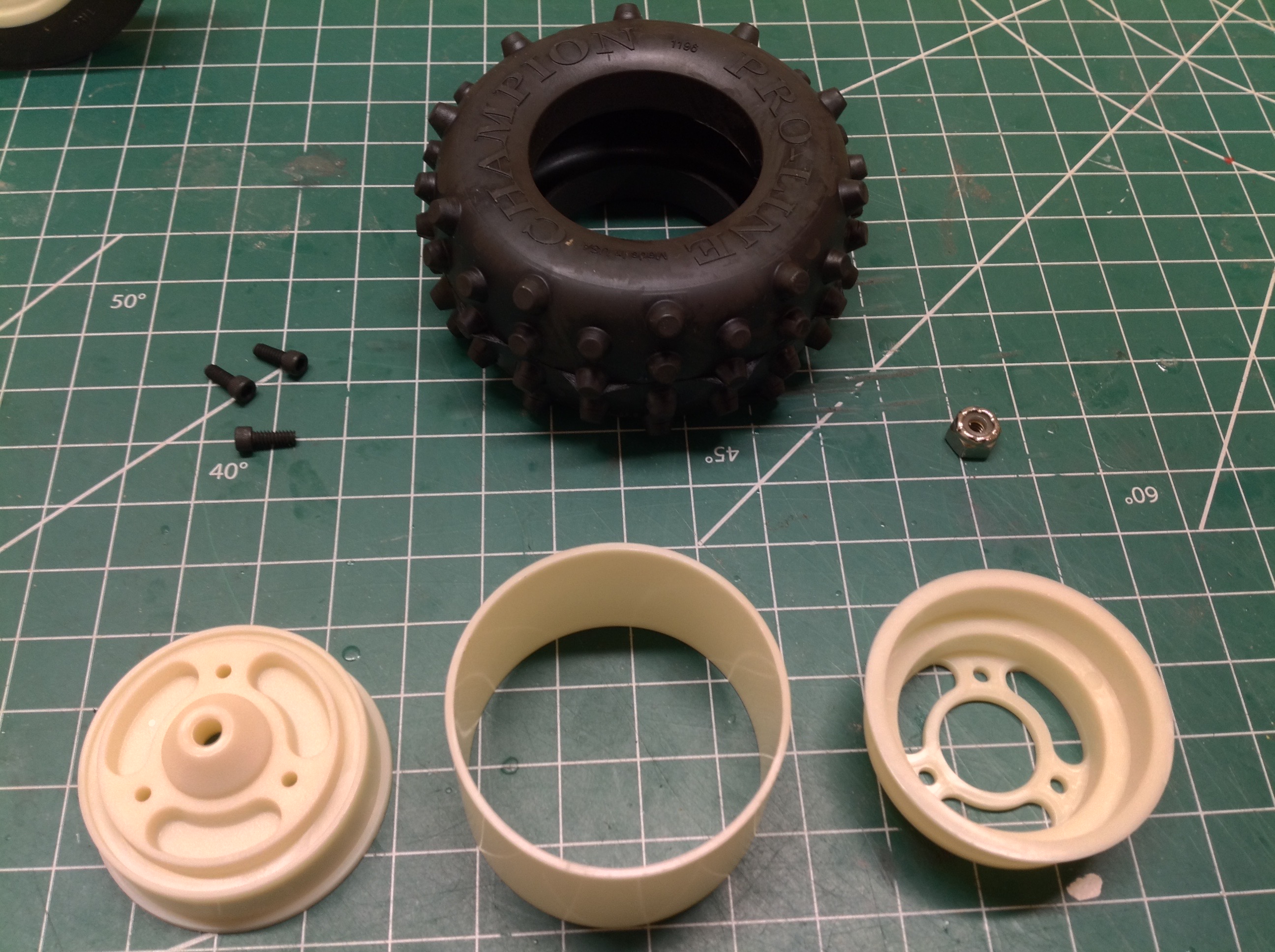
The reproduction tires included in the kit are made by Proline of a
soft, durable compound. The wheels are a 3-piece beadlock
type. The rear tires are wide and spiked while the front are
narrow and grooved.
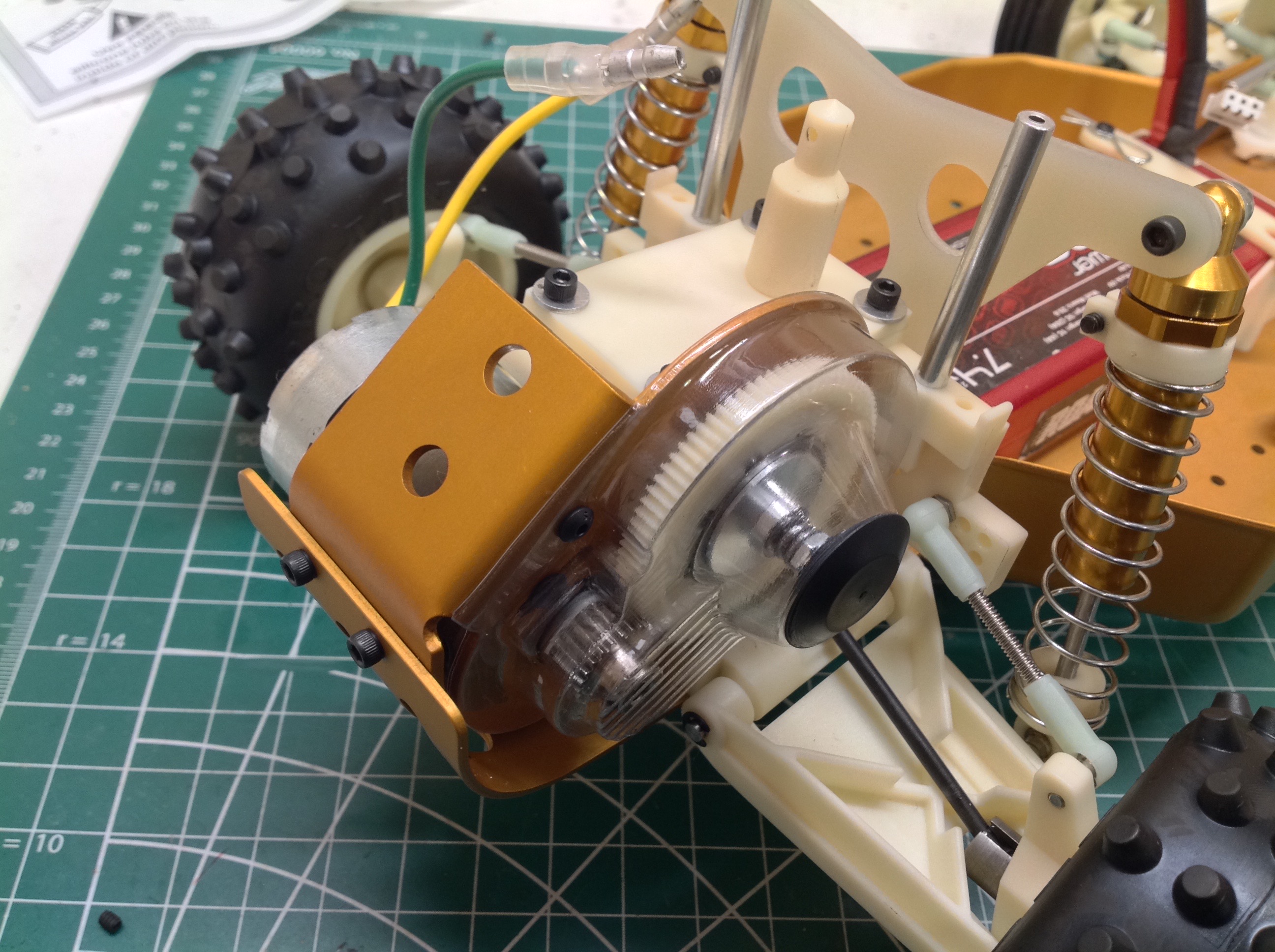
I installed a temporary silver can motor while I waited for something
more suitable to arrive. The protective gear cover is clear to
show off the gear set. The kit did not include a pinion so I chose
an 18T 48p pinion from Robinson Racing. The kit accepts pinions
from 18 to 27 teeth. I used the smallest pinion because I intend
to use a fairly hot motor, a Reedy 19T Super Stock.
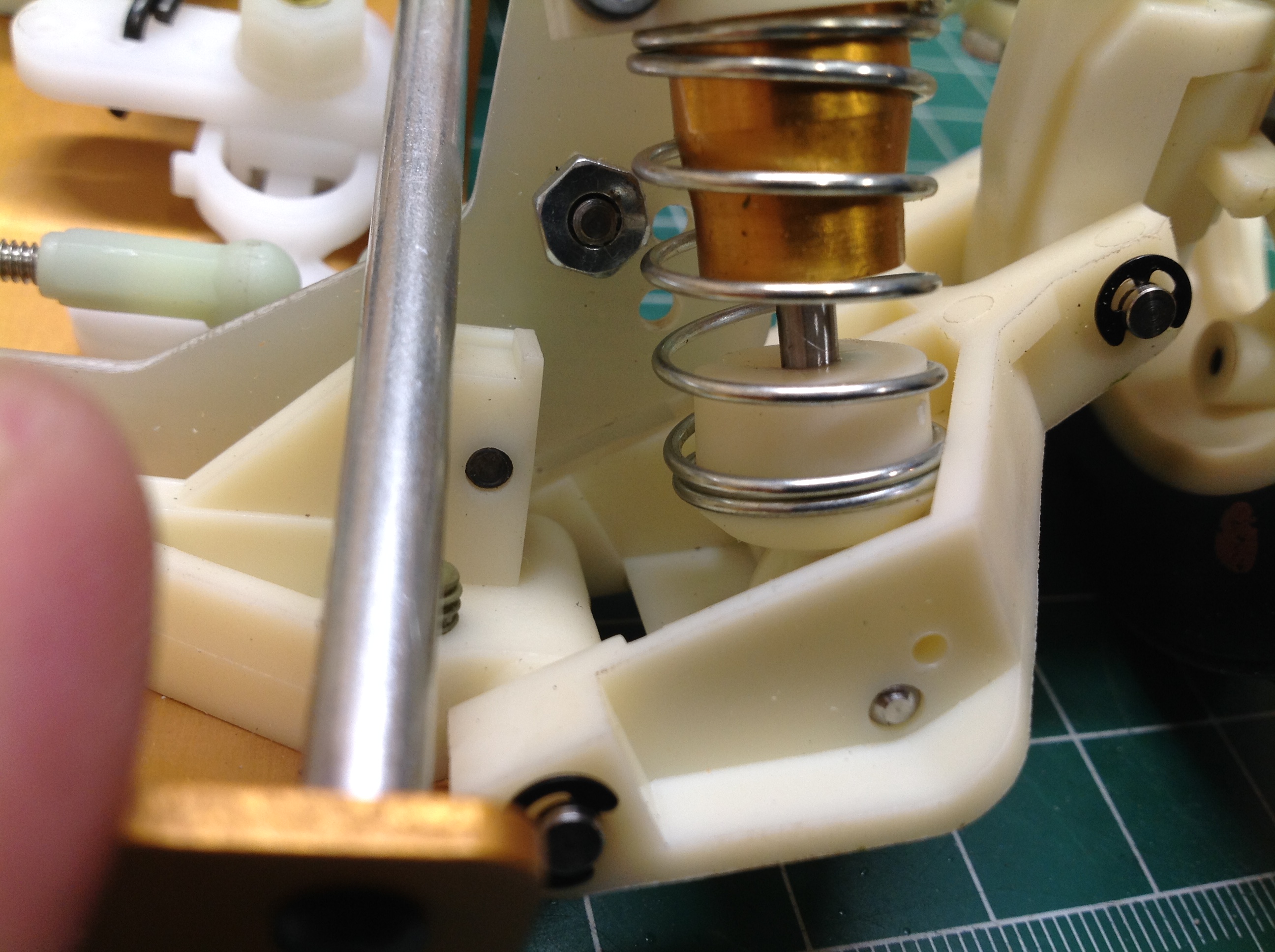
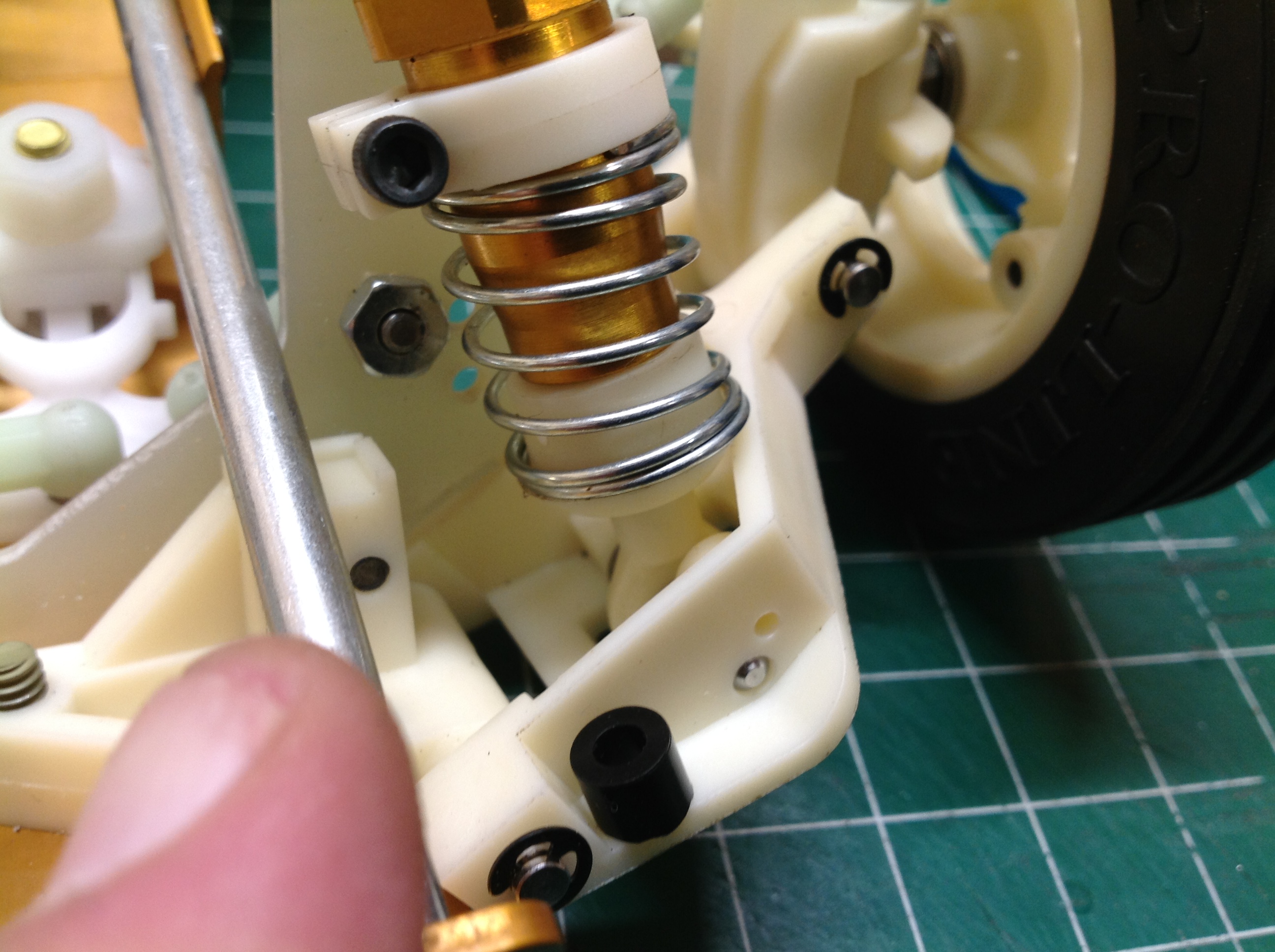
I'd like to highlight one bad design feature which I circumvented.
The travel of the front suspension is very small because the large
spring perch hits the side of the pocket in the lower suspension arm as
shown on the left. On the right, I've inserted one of the black
spacers shown to put some space between the rod end and the spring
perch. This totally solved the problem and doubled the suspension
travel.
©2020 Eric Albrecht