Vanquish Ripper Project

Page 1:  Assembly


The Ripper ships in an unassuming white box with a sticker on the lid.  This is not too surprising given how few of these have ever sold.  Inside you'll find a manual and an apparently pre-built model.  Looking more closely, you can see that the cage and body panels were simply screwed together as the safest way of protecting them during shipping.  The model is cradled in some foam blocks.  The other included parts such as links, lights, and hardware are stashed inside the body.


The left hand image shows the contents of the box unpacked.  The contents of the plastic bags include the headlights, light bars, battery tray, links, bumper, and hardware.  There really isn't that much here.  The right hand image shows most of the other parts which I had to acquire separately in order to try to complete the project.  These include a brushless power system, chassis rails, axles, drive shafts, tires, servo mount, drivers, and body accessories.  It is hard to know exactly what to buy prior to having the kit in hand, and I made more than a few mistakes in this regard which had to be corrected as I built.


The first thing I did was to remove the screws used to ship the cage.  The cage is machined in five parts which include the two sides and three cross members.  The cross members consist of a spare tire mount, a roof, and a front suspension mount.  Each of these five parts is machined from a single block of aluminum.  The blocks for the sides must have been particularly huge given that the tubes are not all in the same plane.  The serial number of my Ripper is engraved on the front of the spare tire mount as shown.  All of my cage parts were anodized in blue.


The cage goes together with just a handful of screws.  From what I can tell, all the hardware is stainless and all the holes are already tapped.  It is really important to use thread lock on all the screw threads.  The completed cage weighs so little you can hardly feel it.  The second image shows the installation of the 3D printed battery tray which sits right behind the engine bay.  It has room for a sizable 3s battery.


The transmission I used for this model was originally built for my Axial SCX10 II Cherokee.  I wanted to include a dig unit on that model but it does not fit with the kit transmission so I had to build up an AX10 transmission from scratch using mostly Vanquish steel gears and aluminum housings.  In the end, I found that I didn't like how much modification was required to the Cherokee to get it to fit so I removed it and saved it for the Ripper.  You can read about the original assembly and see photos on my Cherokee upgrade page.  The left hand image shows the transmission and dig installed along with a nice aluminum skid plate I got from eBay.  I bought an SCX10 II cross member set to use with the chassis rails, but then realized this model only works with the original SCX10 cross members, not the SCX10 II.  Off to the Internet to wait for some more parts.  I kept on going with the build while I waited.  I used a Castle brushless crawler system.  The right hand image shows the cage attached to the chassis at which point this whole thing is indestructible.


The axles had to be purchased separately and I chose to go with the F9 Currie portal axles which had only just been released by Vanquish.  There are an amazing number of parts in something as simple as a rear axle as shown.  The housing, 3rd member, bearing caps, and wheel hexes are all milled aluminum.  The gears are steel.  The portal gears are straight cut and the ring and pinion gears are spiral cut.  Axles, locker, and wheel spindles seem to be hardened.  There's even a lube cap for the diff housing!


The first thing to do is screw the ring gear to the steel locker.  After the pinion is installed to the 3rd member, the locker bearings are installed and retained by a pair of pillow blocks. I did not find that any shimming was required.  Note that these are hypoid gears which means that the pinion gear enters the housing above the centerline for reduced driveshaft angle.  The right hand image shows the portal setup.  A small spur gear is installed on the axle and then a larger gear locked to the wheel spindle provides output.  This arrangement results in gear reduction in the hub providing more torque at the wheels without overstressing the drivetrain.


Now all the screws attaching the portal covers and 3rd member can be installed to button up the rear axle assembly.  This axle is probably as heavy as the whole cage.  The four steel links can then be built and attached to the rear axle as shown.  There are a lot of rod ends and ball joints to install, so make sure you are well rested.


The 4 links attach to the chassis with 4 screws, and it is important not to forget to install the steel Incision drive shaft at the same time.  The first set of 90mm Incision shocks come next.  These come pre-built in the package but shock oil needs to be added.  I was worried they would be too small for this truck, but I actually find their amount of spring rate and damping to be just right.  At this point you can also see the flat black plates on either side of the center skid.  These serve as sliders and also provide a nice flat surface for mounting electronics.


The assembly of the front axle is similar to that of the rear with the added complexity of steering.  The axles are CVD style.  The axle has both kingpin inclination and caster angle, but both are fixed.


Like the rear axle, we need to build and attach 4 suspension links.  Unlike the rear, we also need to install a couple of steering rods.  One links the left and right hubs together, and the other goes to the steering servo.  This vehicle uses an axle mounted servo system which must be purchased separately.  I chose to use one of the best crawler servos money can buy, a Protek Black Label with a Vanquish aluminum arm.


The front links can now be installed and the shocks attached.  I normally don't like the appearance of axle mounted servos, but in this case the servo tucks up inside the body and can't really be seen so it works just fine and avoids bump steer.  At this point I've also installed the aluminum front bumper and the radiator fan.  Unless you manage to install your ESC under the hood (which I didn't), the fan doesn't really blow on anything.  There are no specifications provided for most of the electronics in the kit, so it might take you some time to figure out that this is a 12V fan.


When I was installing the front bumper I ran into a big problem.  The threads for one of the holes were not very good and I didn't realize how soft the stainless screws were and sheared off one of the heads trying to install it.  I spent hours trying to remove it without success and finally had to drill it out and retap to 4mm.  The left hand image shows the broken head and new, larger hole.  It is ugly, but probably no one will notice except me.  The right hand image shows the installation of the included anti-sway bar in the rear.


The instructions call for the installation of an Axial fuel cell in the back, but it didn't fit with the dig unit I installed so I had to do some strategic trimming as shown.  After that it installed fine.  I'm not using the fuel cell for any electronics so it just sits empty.  The right hand image also shows the radiator installed.


The chassis is now nearly complete.  Cage and frame rails are assembled, axles and shocks are installed, and so are plastic accessories as shown on the left.  On the right I've added the front machined grille and the headlights.  These 12V lights are unbelievably bright and must be wired together in parallel and then pass in series through a regulator before going to the battery or a switch.


One of the big problems I had getting ready to build this kit was part availability from Vanquish.  I had to wait months for the axles, and as of this writing the wheels are still not available.  For this picture I installed some old plastic G-made beadlocks I had lying around onto some RC4WD Goodyear Wrangler MT/R tires.  The final wheels will be anodized blue like the cage.  I've also installed the front and rear light bars at this point.  On the right you can also see the 3D printed inner fenders I added.  These do a lot to hide the wiring when looking through the large wheel well opening.


This image shows my attempt to clean up the wiring.  I bundled the headlights, light bars, and fan through a remote switch from HeyOK.  This allows me to remotely turn the lights on and off and also dim them in 3 stages.  I added an additional 1" light bar on the front bumper.  The left hand image shows my attempt to bundle and clean up the wiring as much as possible.  Most of it is well hidden once the body panels and drivers are installed as shown on the right.  The black body panels look quite plain and, in retrospect, I wish I had been able to get more color into the final model appearance.


Here are the lights at full intensity.   You can easily drive around at night with these lights.  The bulk of the illuminations comes from the focused headlights while the light bars provide much more diffuse light.  You can also see here that I forgot to order a 5th tire for a spare so I'm temporarily using something completely different.


Although the stickers from Freqeskinz don't add any color, they do add a lot of character.  I also added a number of stickers from the manufacturers of some of the other equipment I installed as you can see behind the "doors".  I painted the drivers blue with gray helmets.


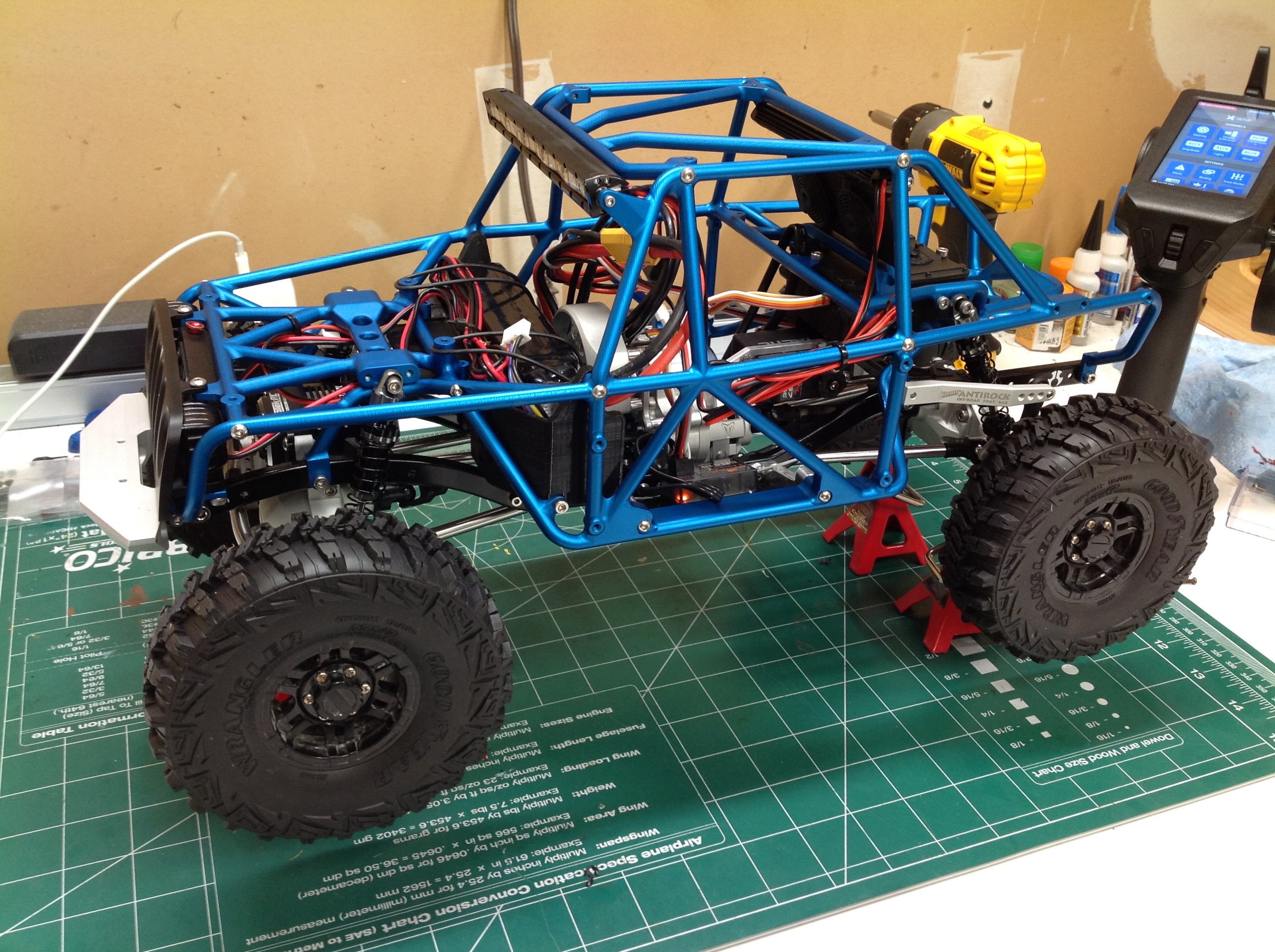
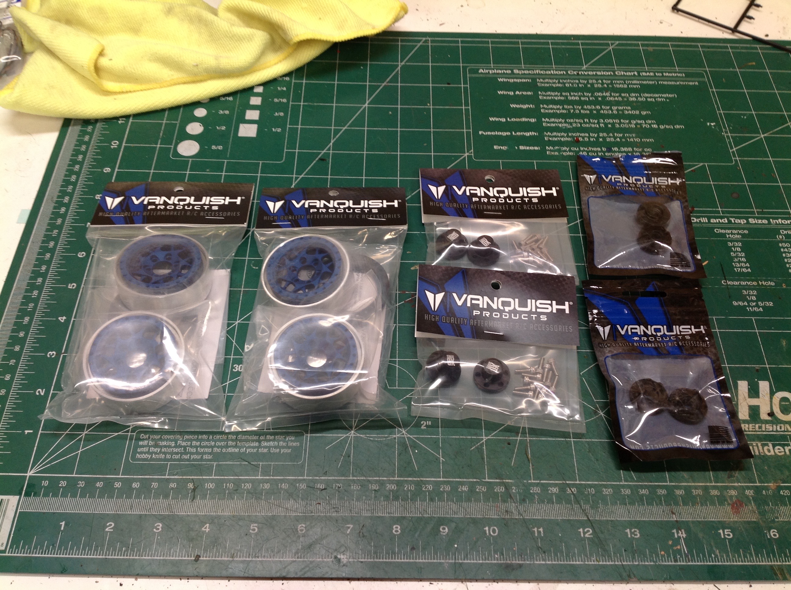
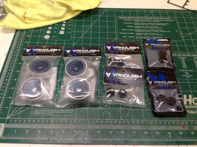
It took almost a year of waiting, but at long last the blue anodized Bully wheels appeared back in stock and I picked up a 
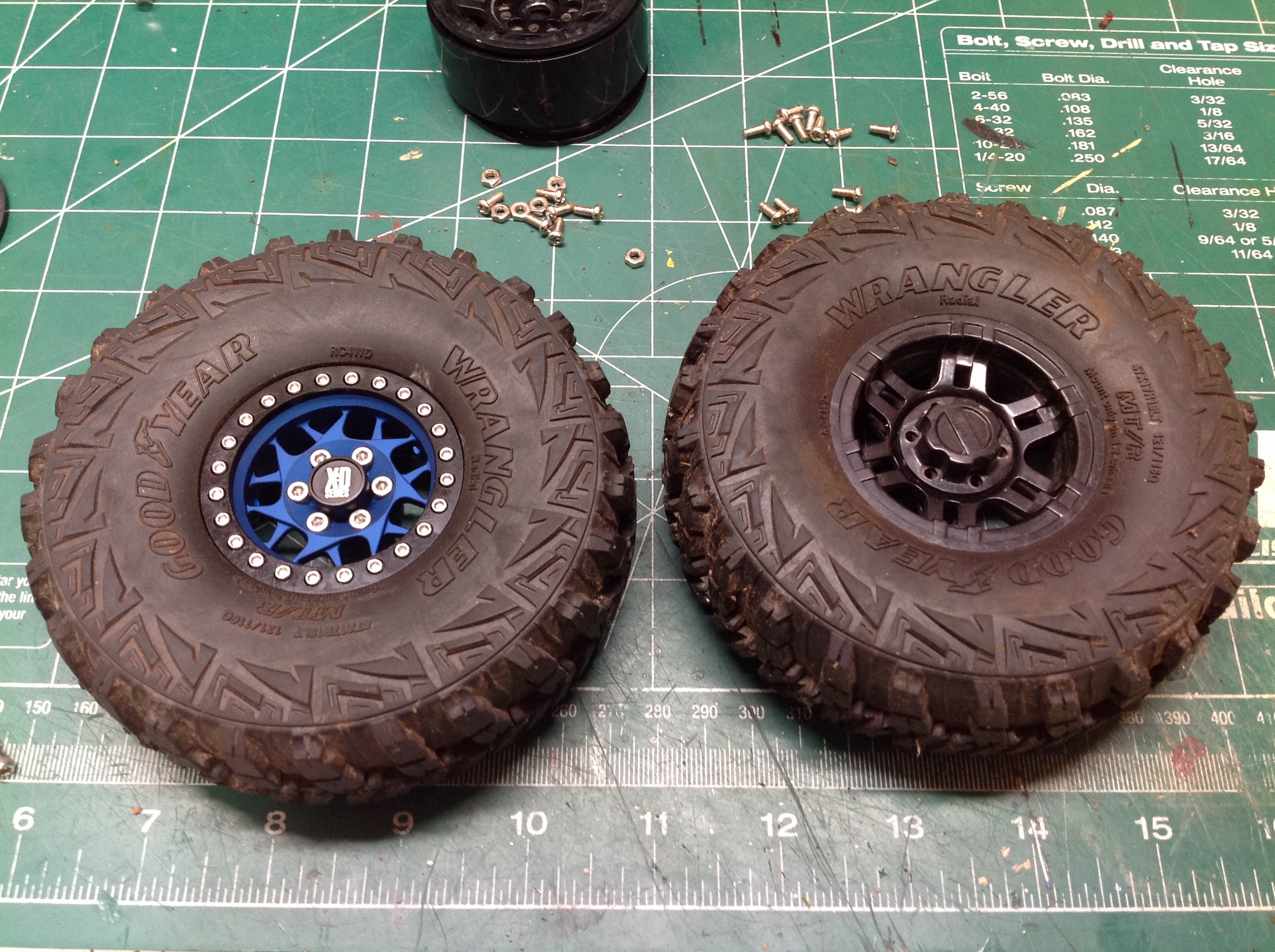
set.  These are aluminum beadlocks.  I'm using 350 offset SLW hubs along with XD center caps.  There were a lot of fasteners I needed to install to mount these up, but the appearance is worth it.


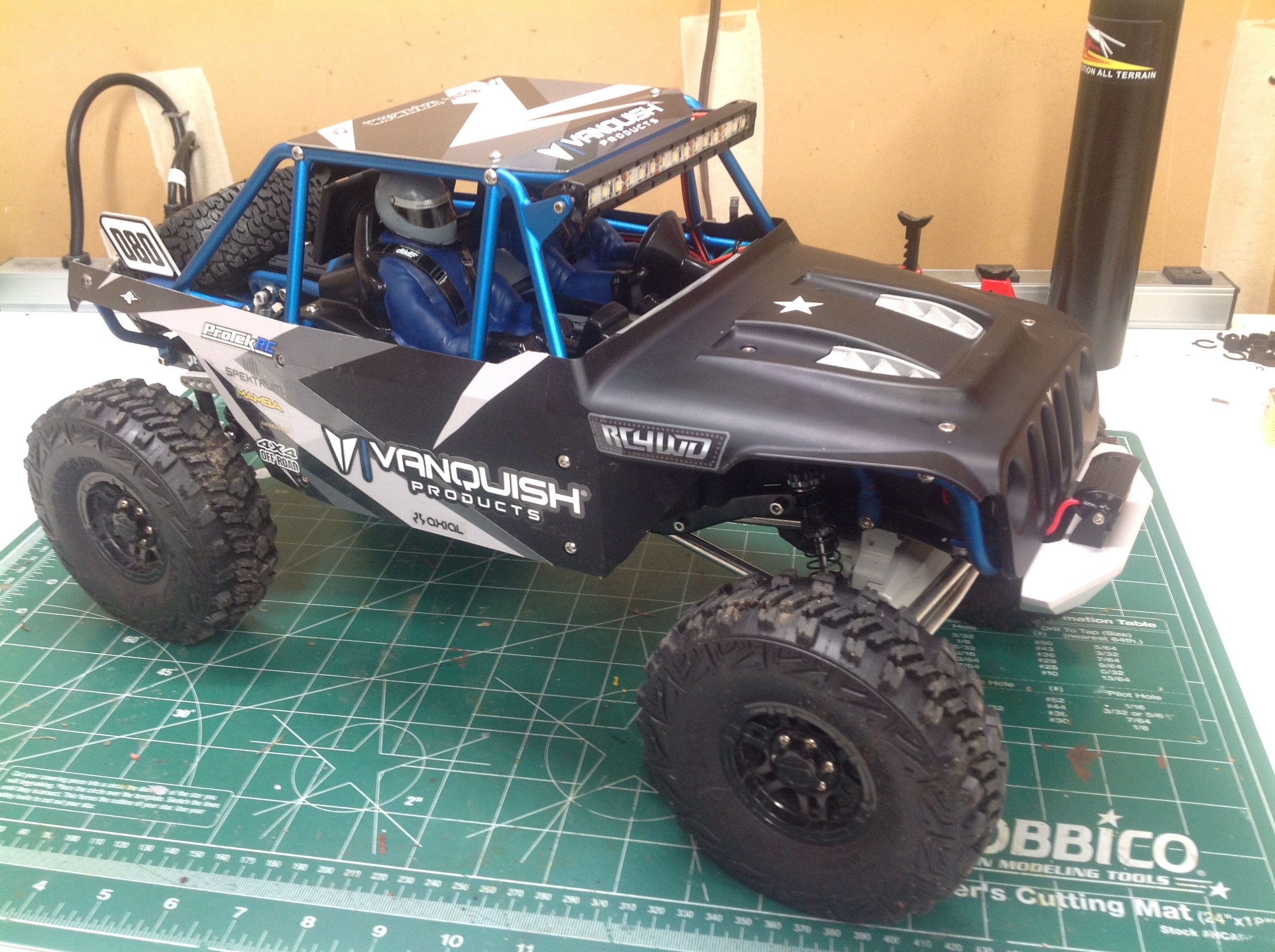
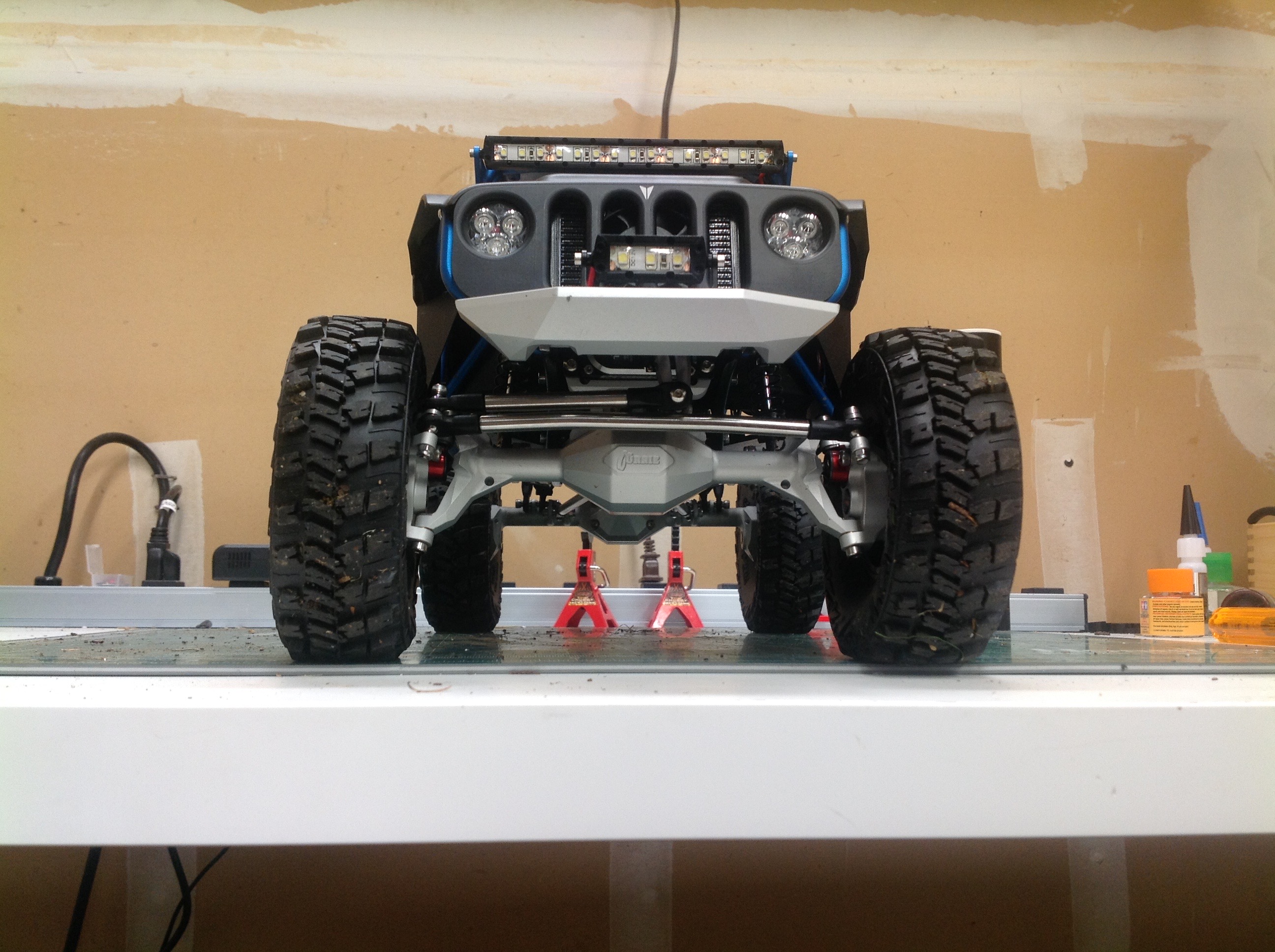
Ground clearance?  Yes please.

Up to Index | Go to Page 2
©2019 Eric Albrecht