Losi Rock Rey Project
Page 1: Stock Assembly
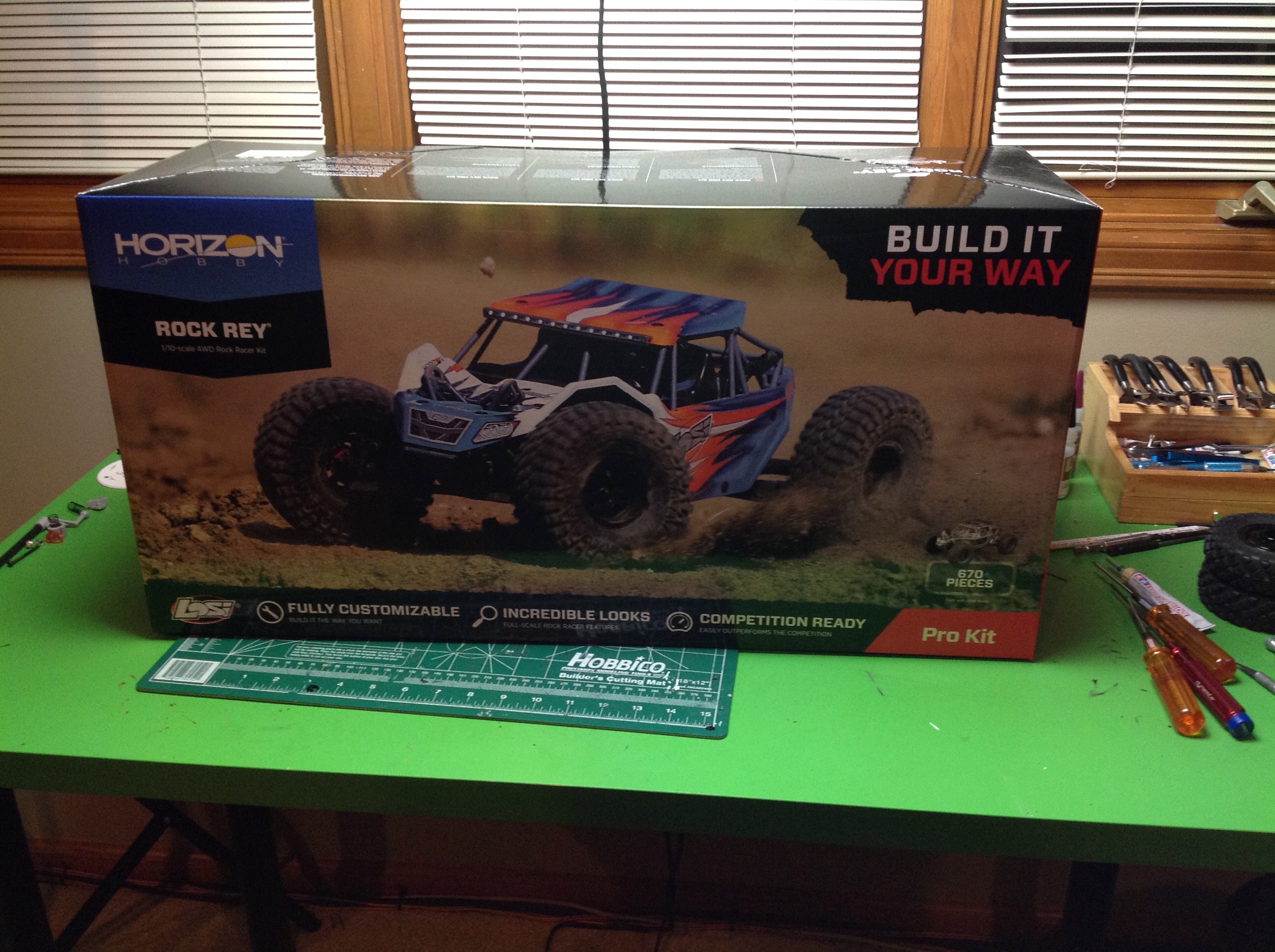
This kit comes in a smaller box than most because it does not need space
for a large Lexan body. Still, the body is larger than you'd
think because it is not just flat panels for the sides and hood, it is a
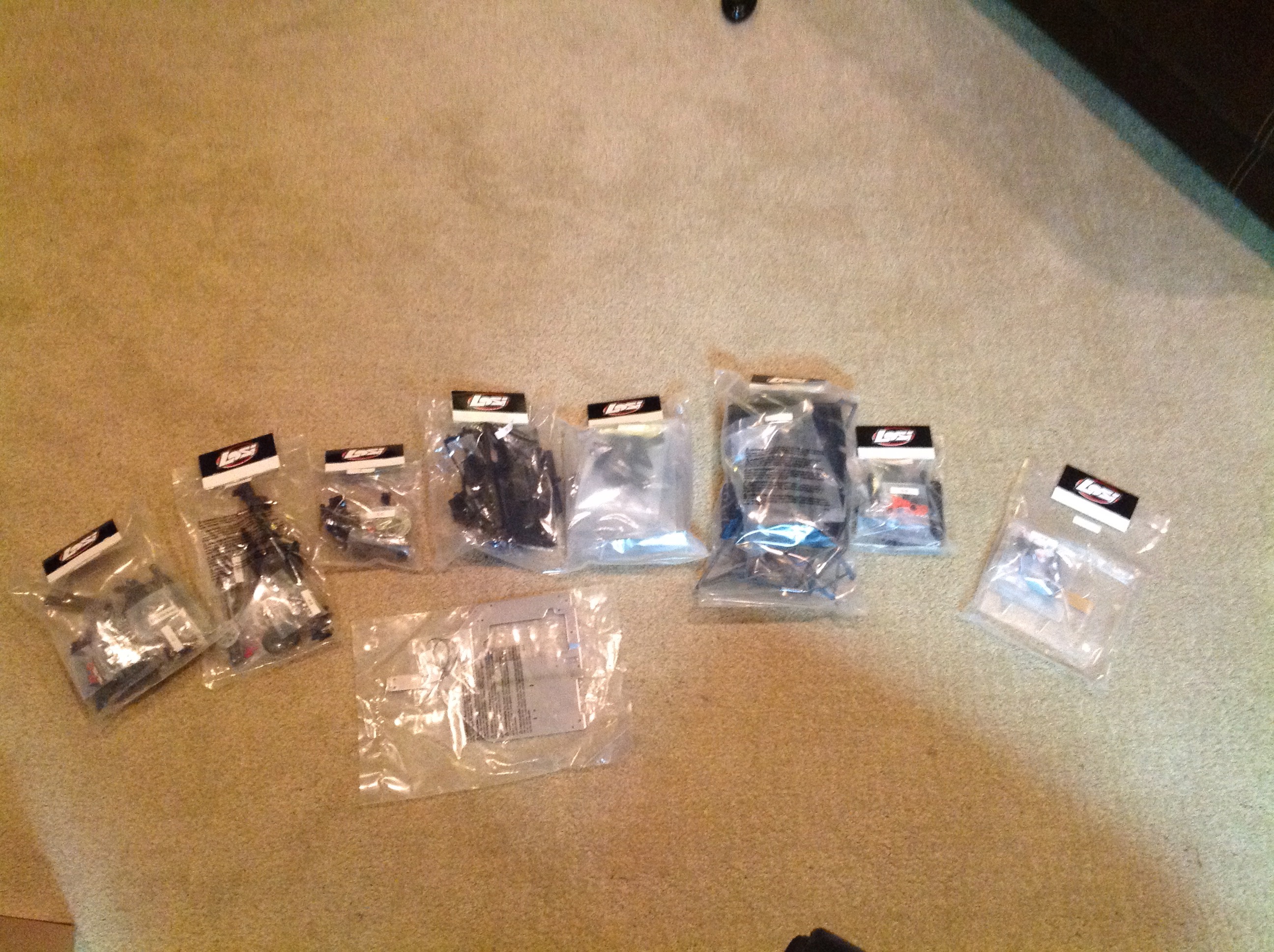
single part that wraps around the front. The horrible picture on
the right shows the way the parts are bagged. They are packaged
almost like separate products with their own label on each bag.
None of the parts needs to be cut out from trees, they are all separated
already.
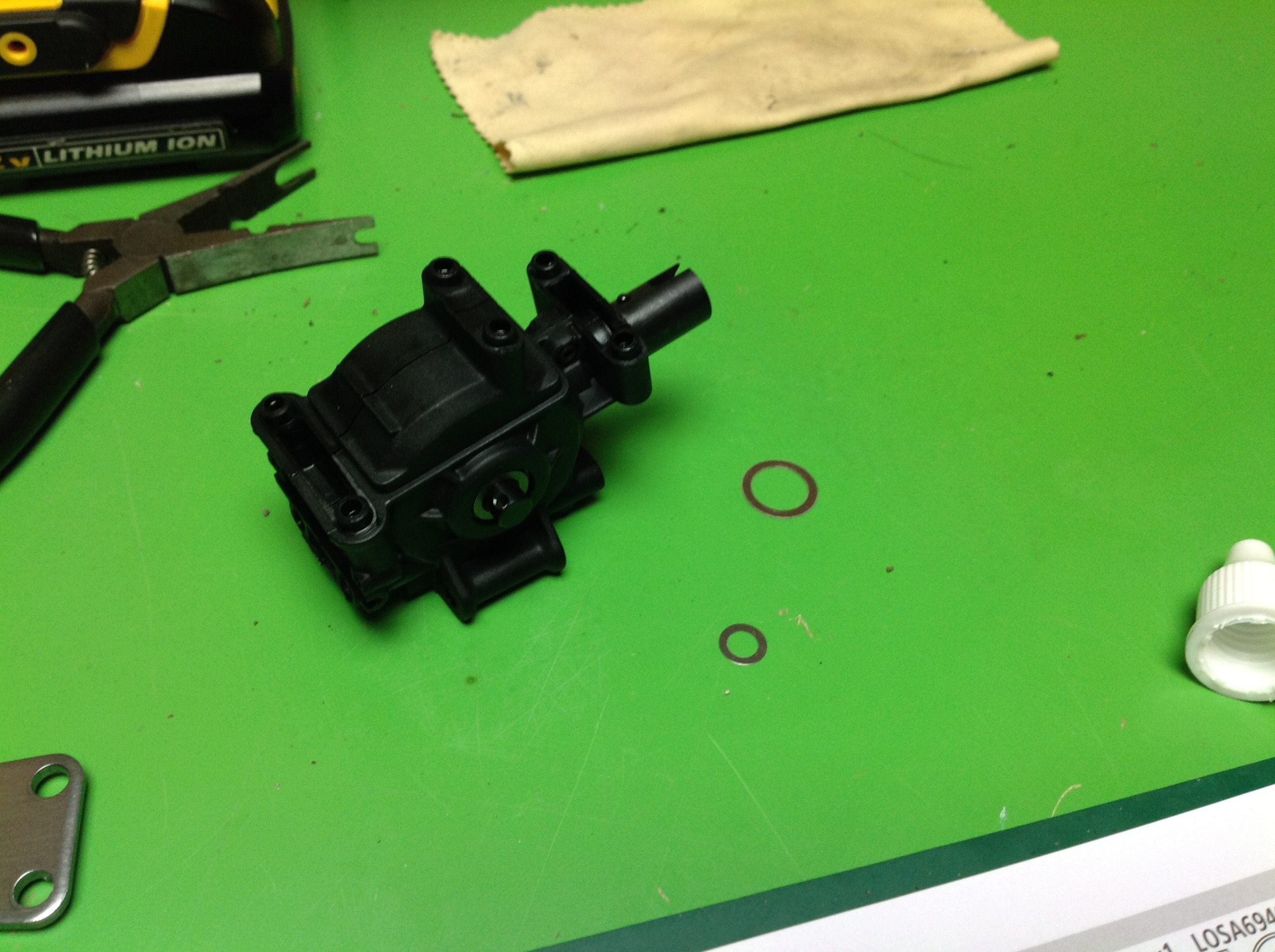
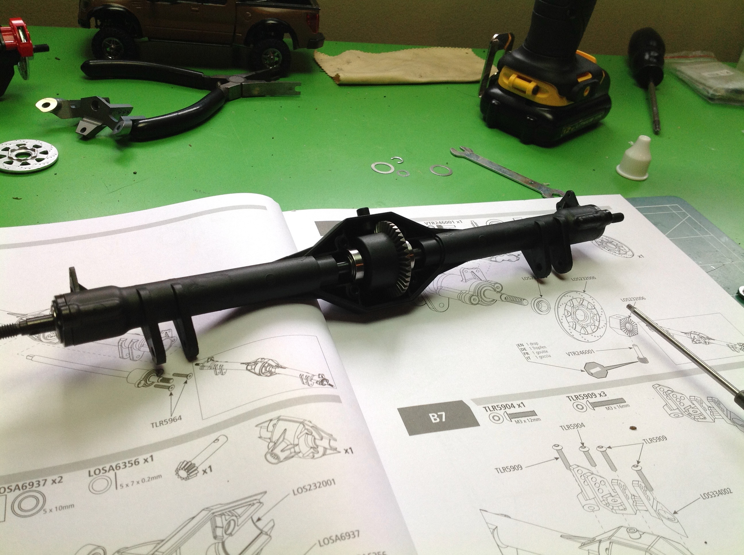
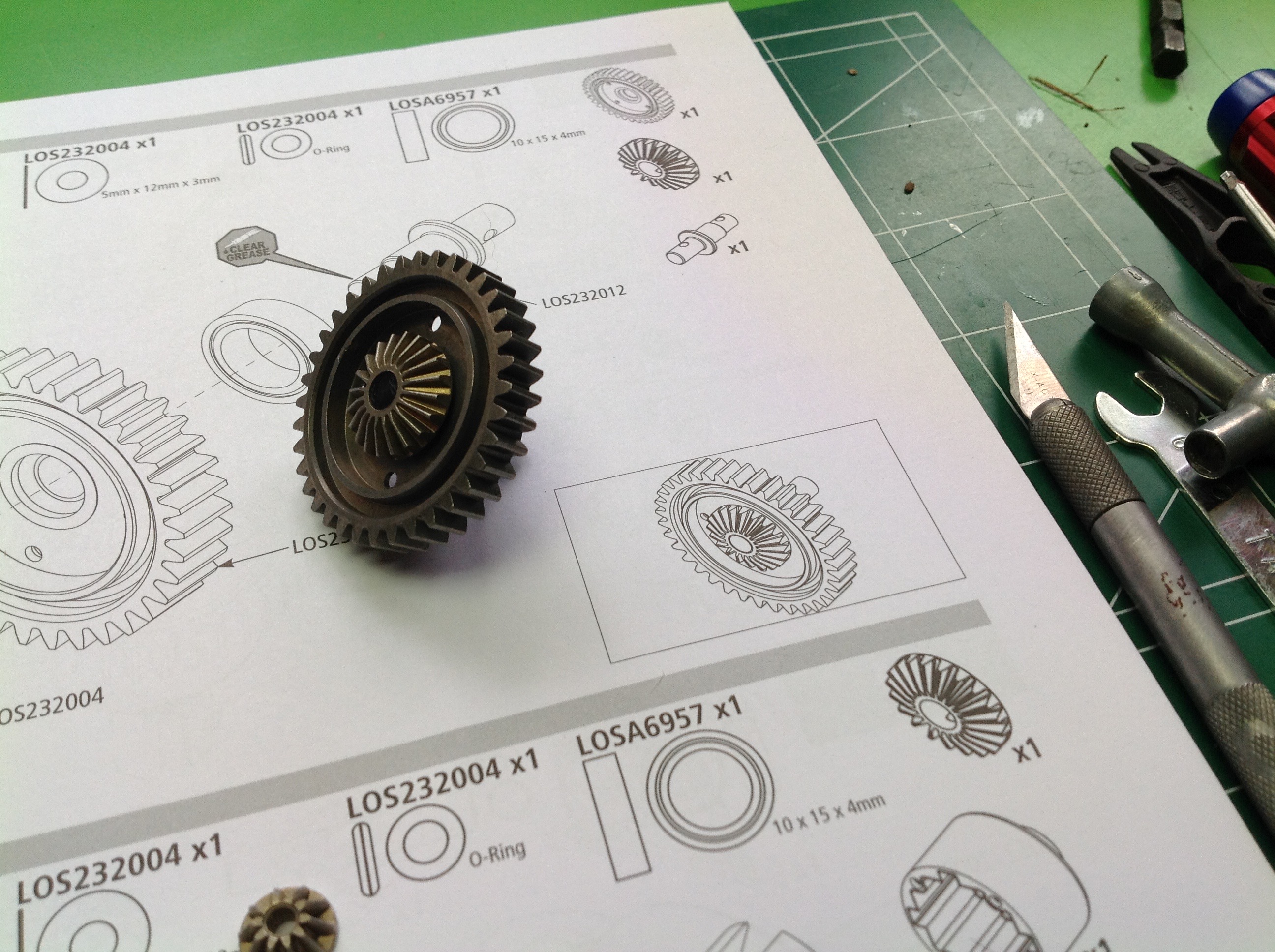
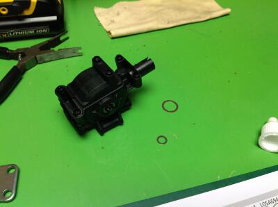
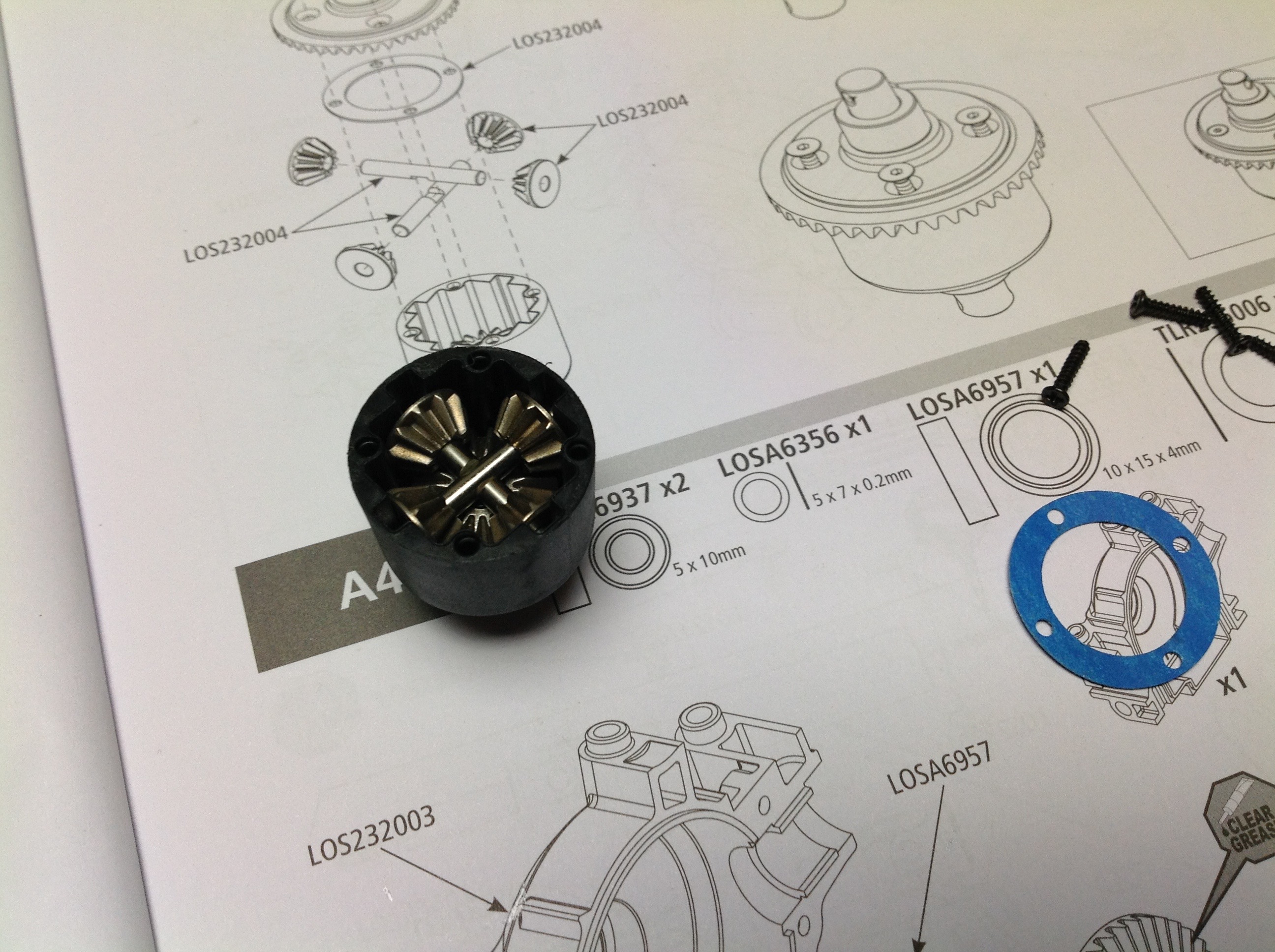
The first part of the build is the sealed front differential. Yes,
this thing actually has a diff and not just a locked axle. The
gears are all steel as are the cross supports. This is a
traditional bevel gear differential and is lubricated with the unknown
grease that comes with the kit. Although this is a sealed diff it
is just greased and not filled per instructions.

r
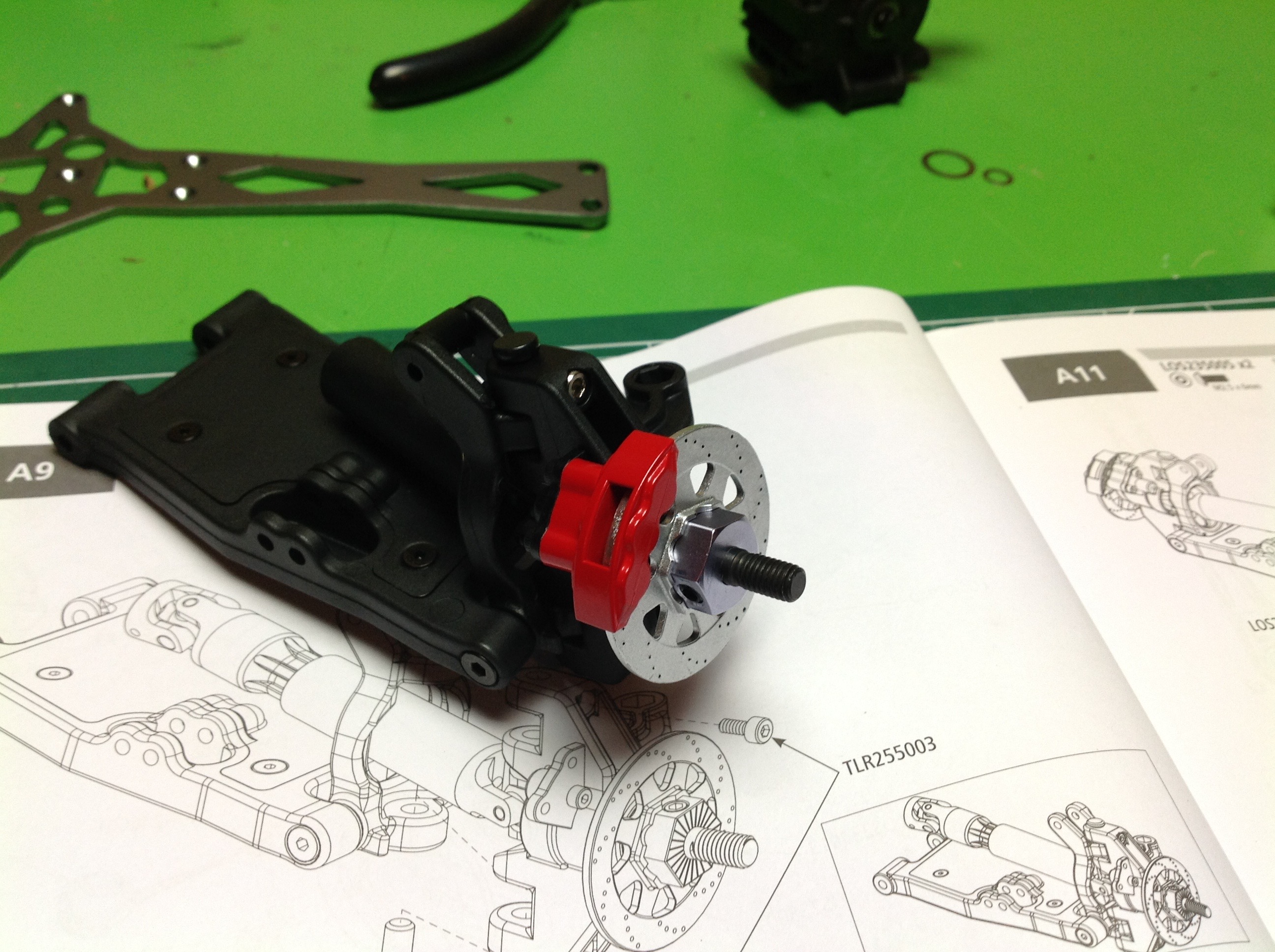
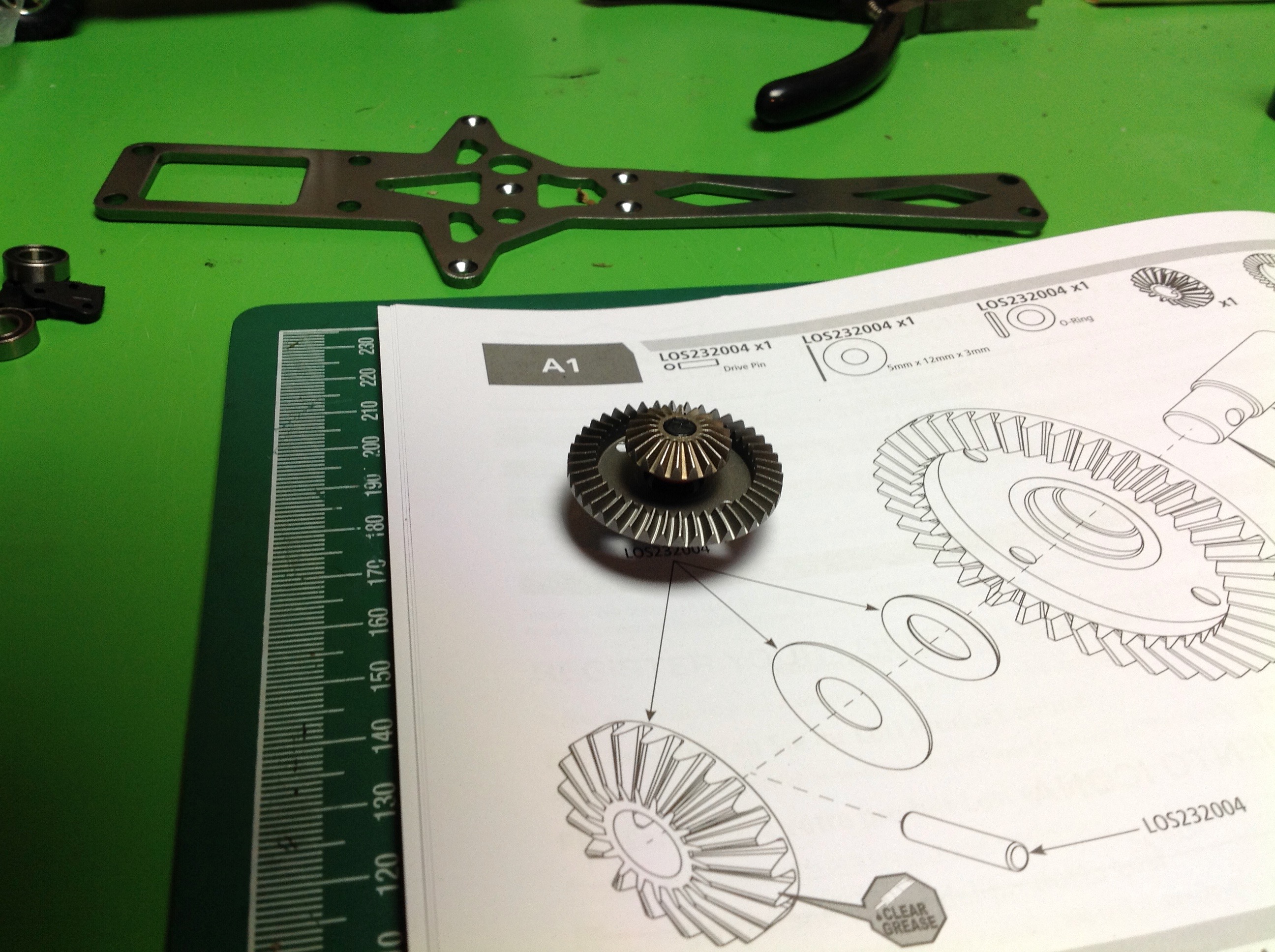
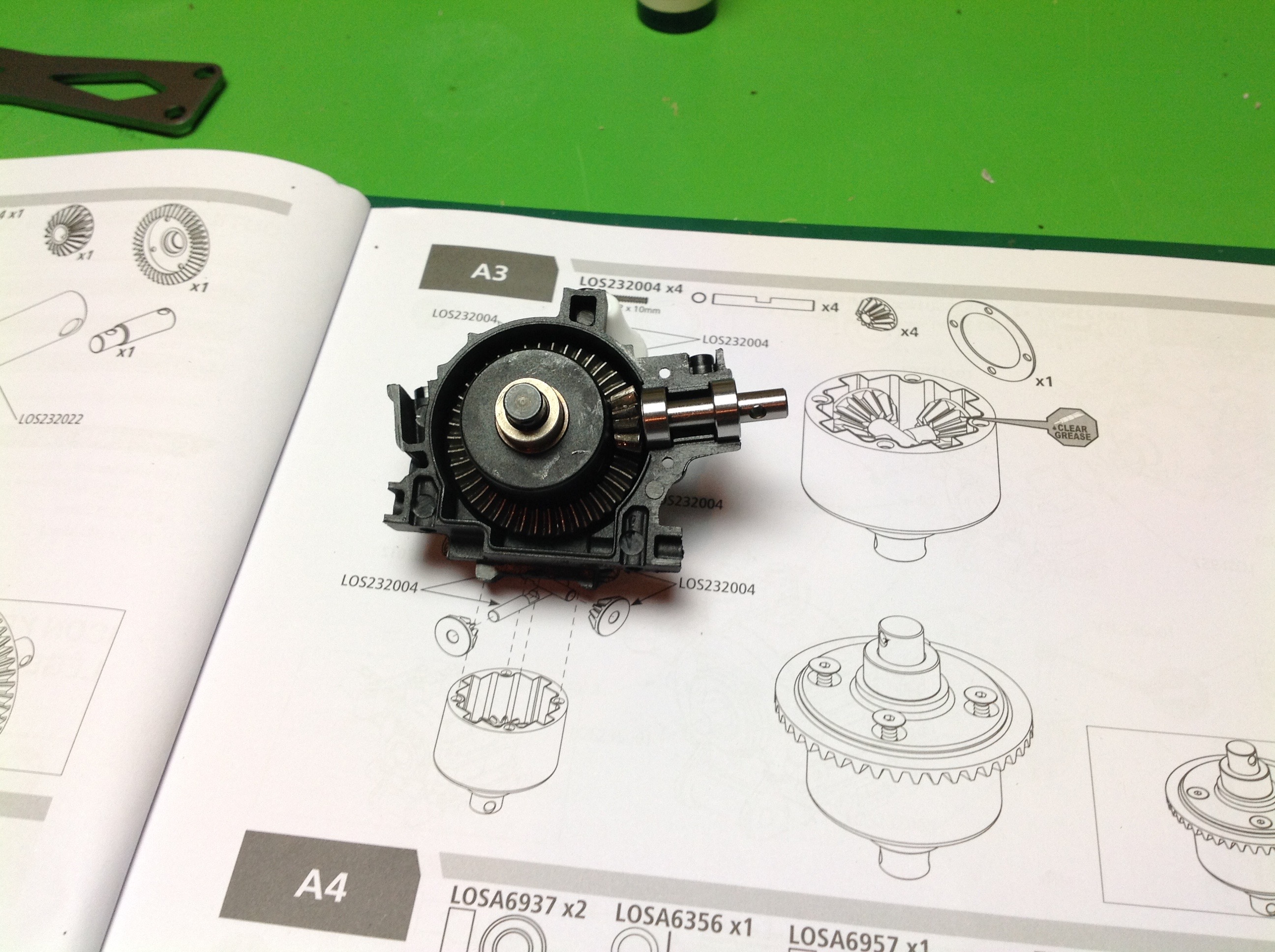
Once the differential is closed up it is put into the front bulkhead
with a pinion that exists at an inclined angle. I found that the
gears did not mesh right when shimmed per the instructions so I ended up
changing the shim configuration a bit. The right hand image shows
the completed front housing. Very compact. The lower
suspension arms will attach to the sides.
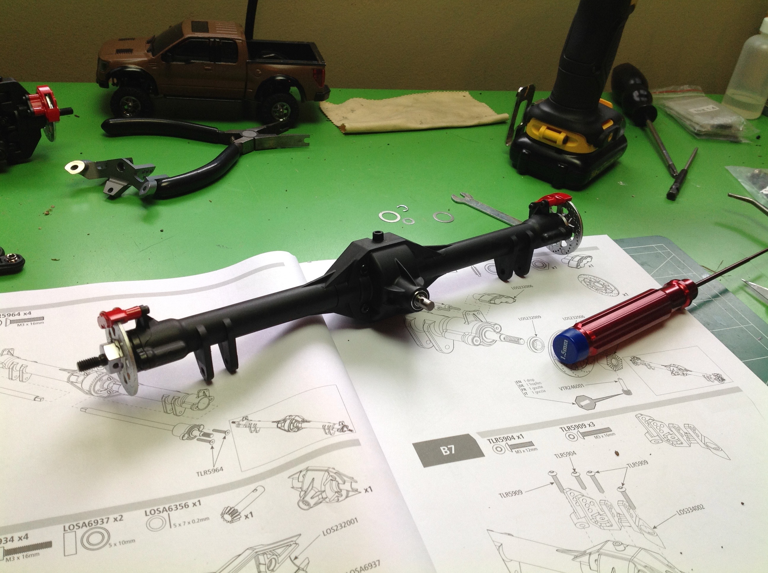
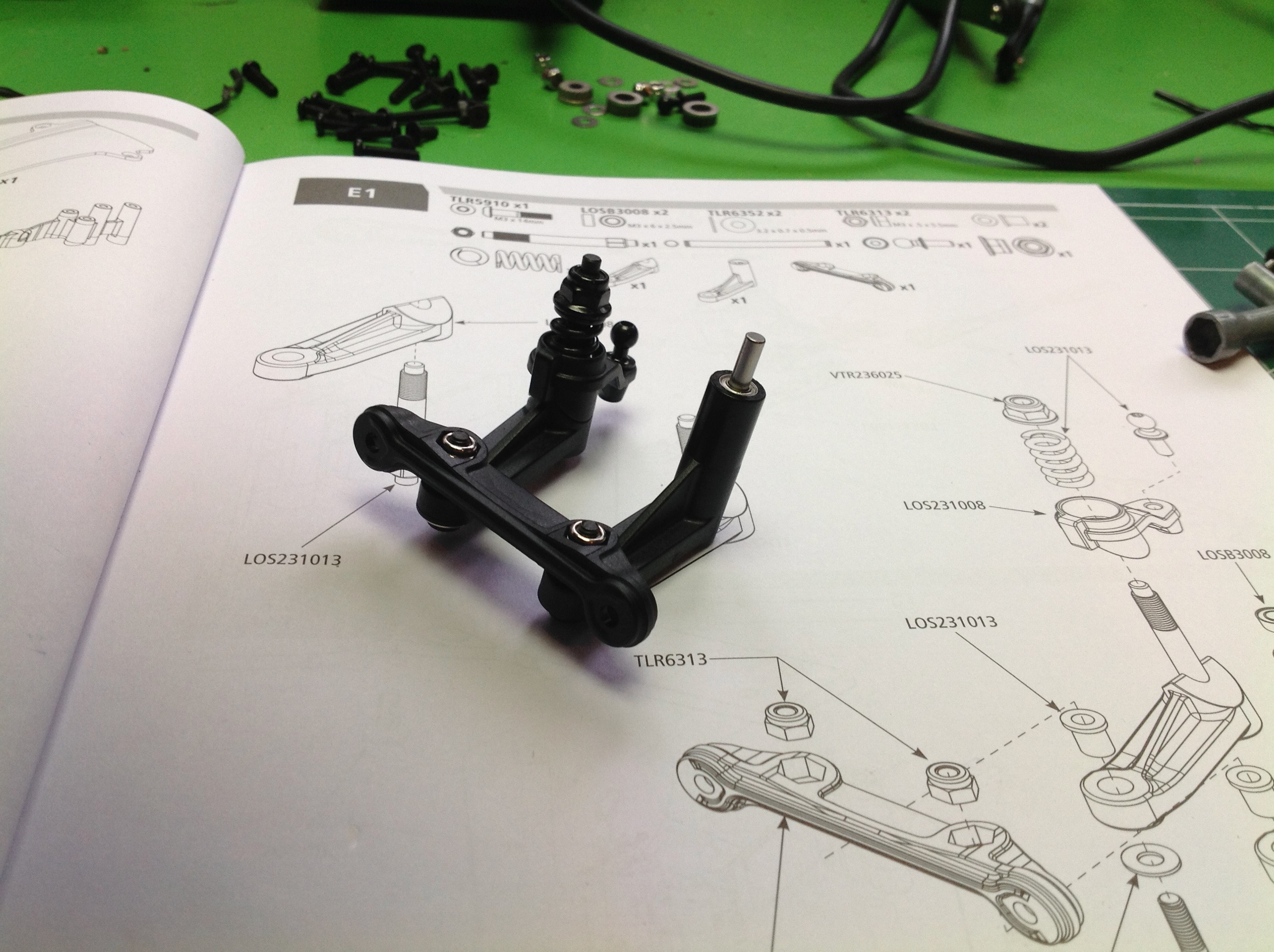
Now we start on the front suspension. The lower arms are actually
two pieces, a molded base and a flat cap that encloses the whole thing
into a rigid, closed box. The C-hubs and steering knuckles are
also plastic but substantial, and there are faux disc brakes on the
axles. I am happy to see that the calipers are actually fixed and
therefore do not rotate with the rotors. The arms are attached to
the front bulkhead and then a thick upper aluminum chassis plate is put
on. The upper arms are metal turnbuckles. Camber is
adjustable, caster is not. The drive shafts are telescoping
splined universals.
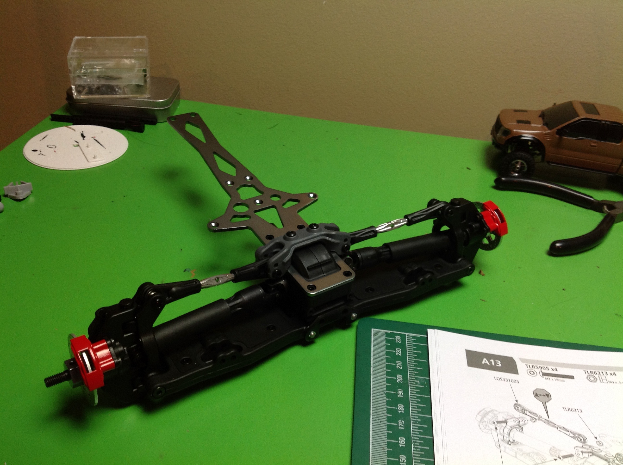
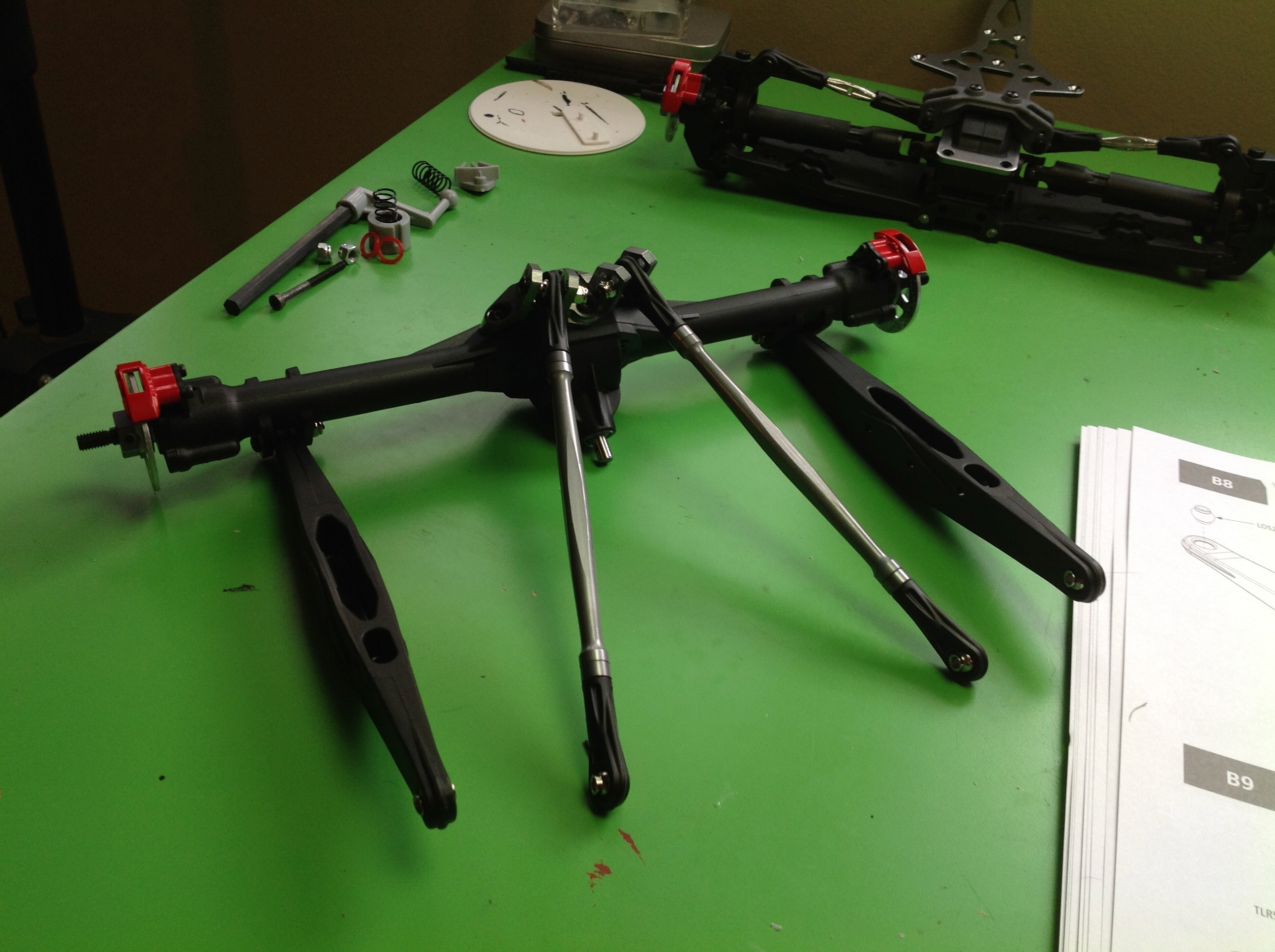
Unlike the front axle, the rear differential is locked which makes the
axle assembly pretty straightforward. You can see that the gears
are spiral cut which is pretty cool.
Once the rear axle is buttoned up, some more brake discs are added to
the axles. Then the 4 rear suspension links are added. The
lower links are thick plastic since they will support the rear shocks
and also may impact the ground, including rocks, during large suspension
movement.
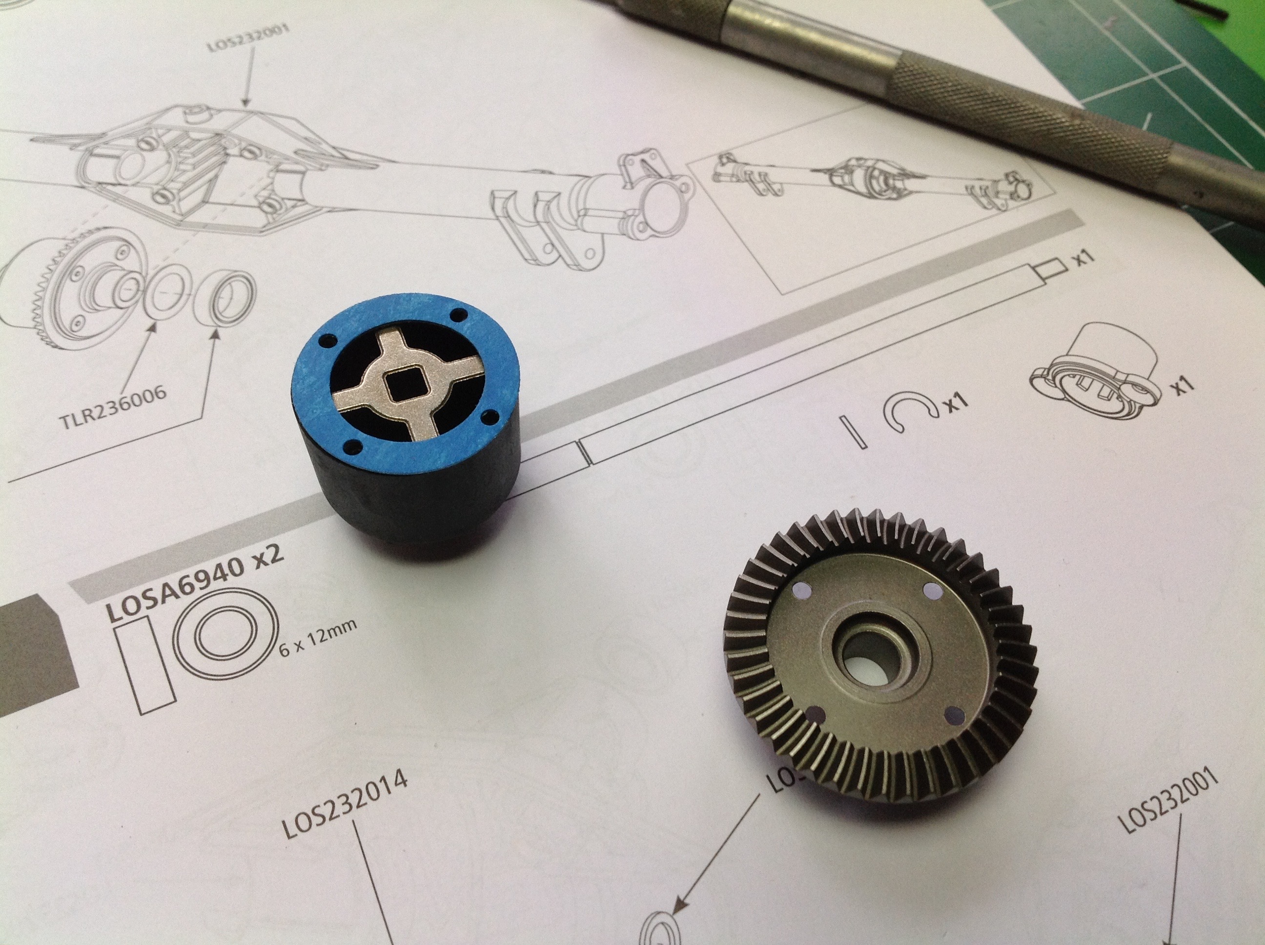
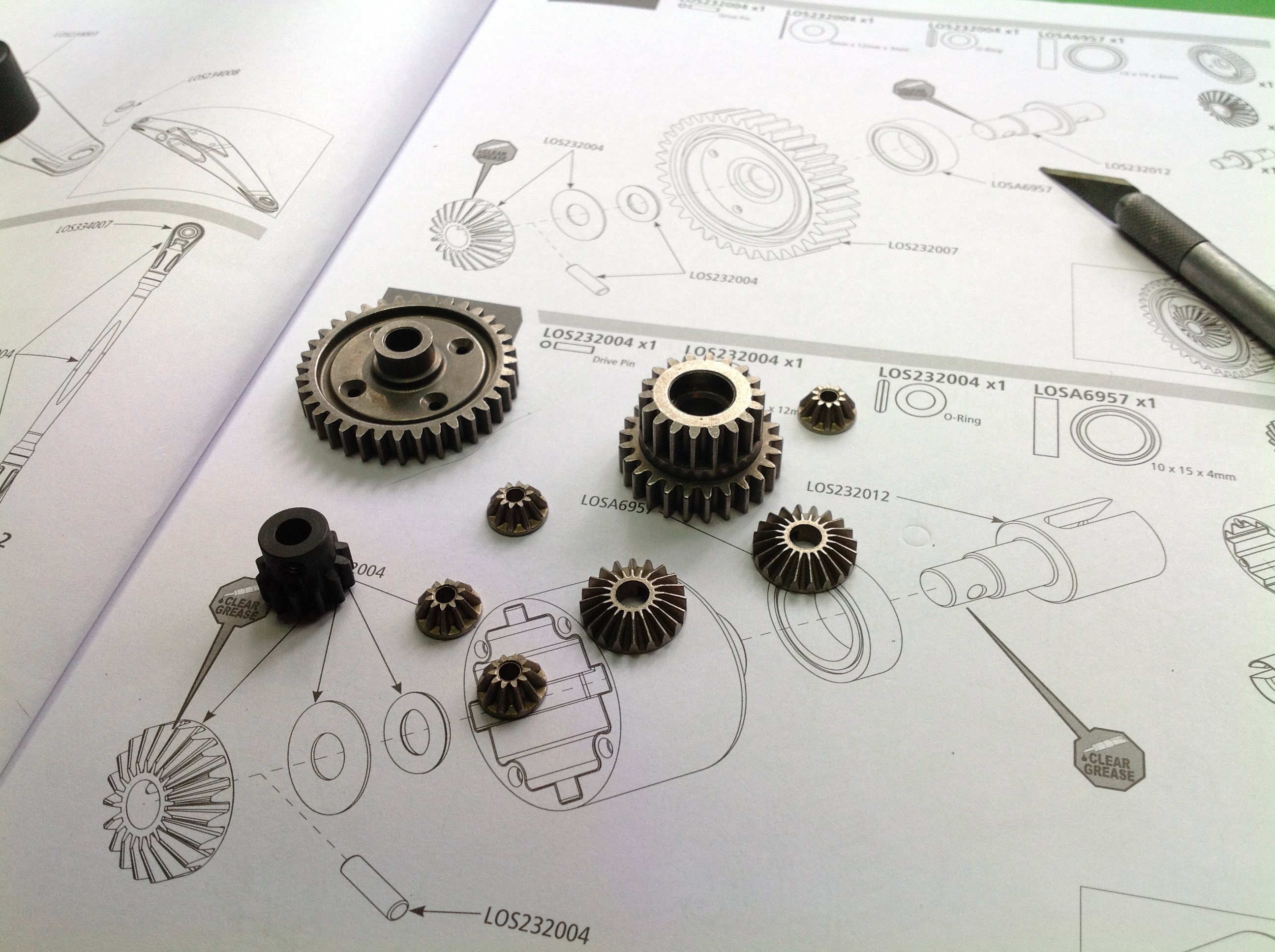
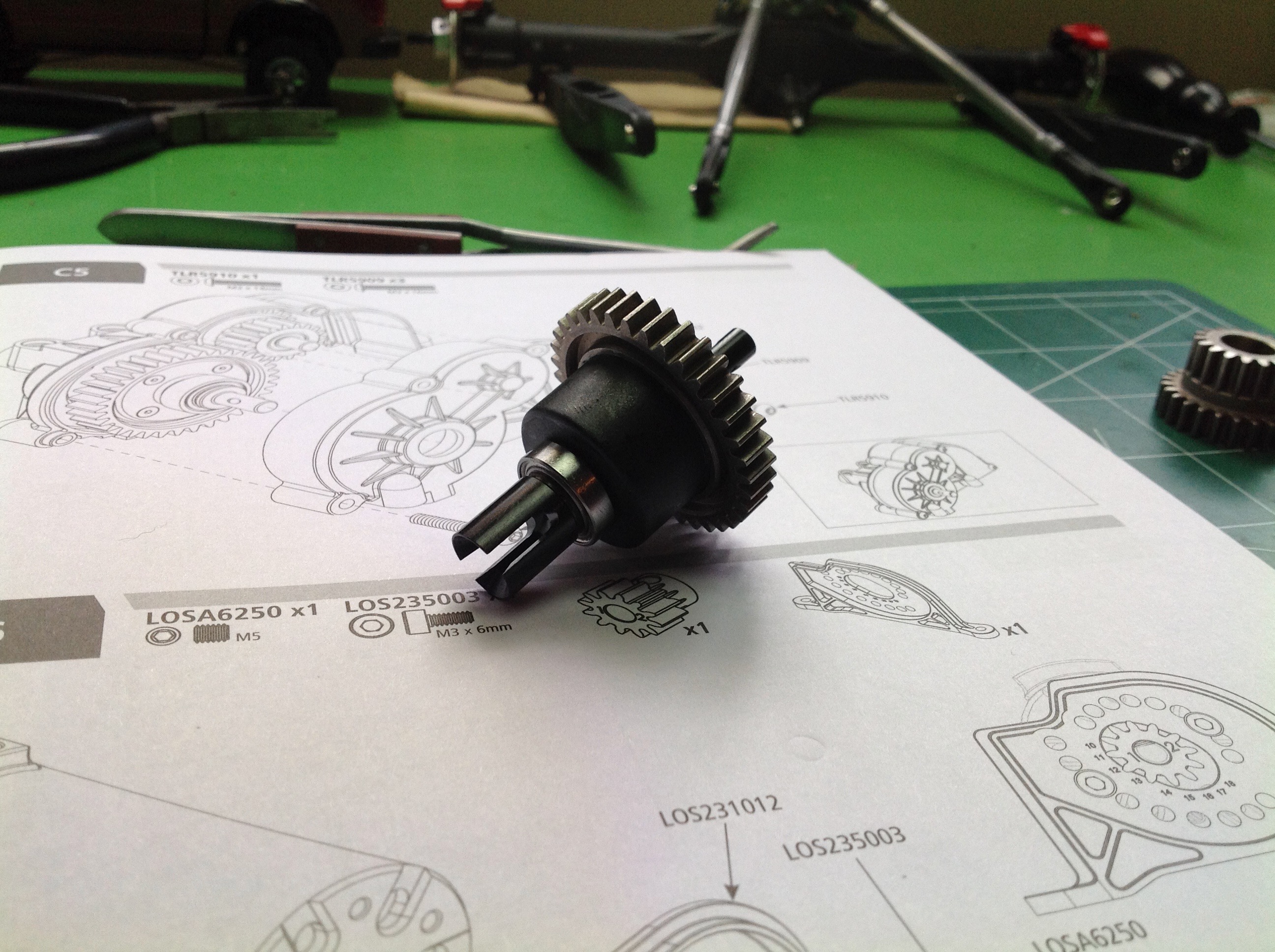
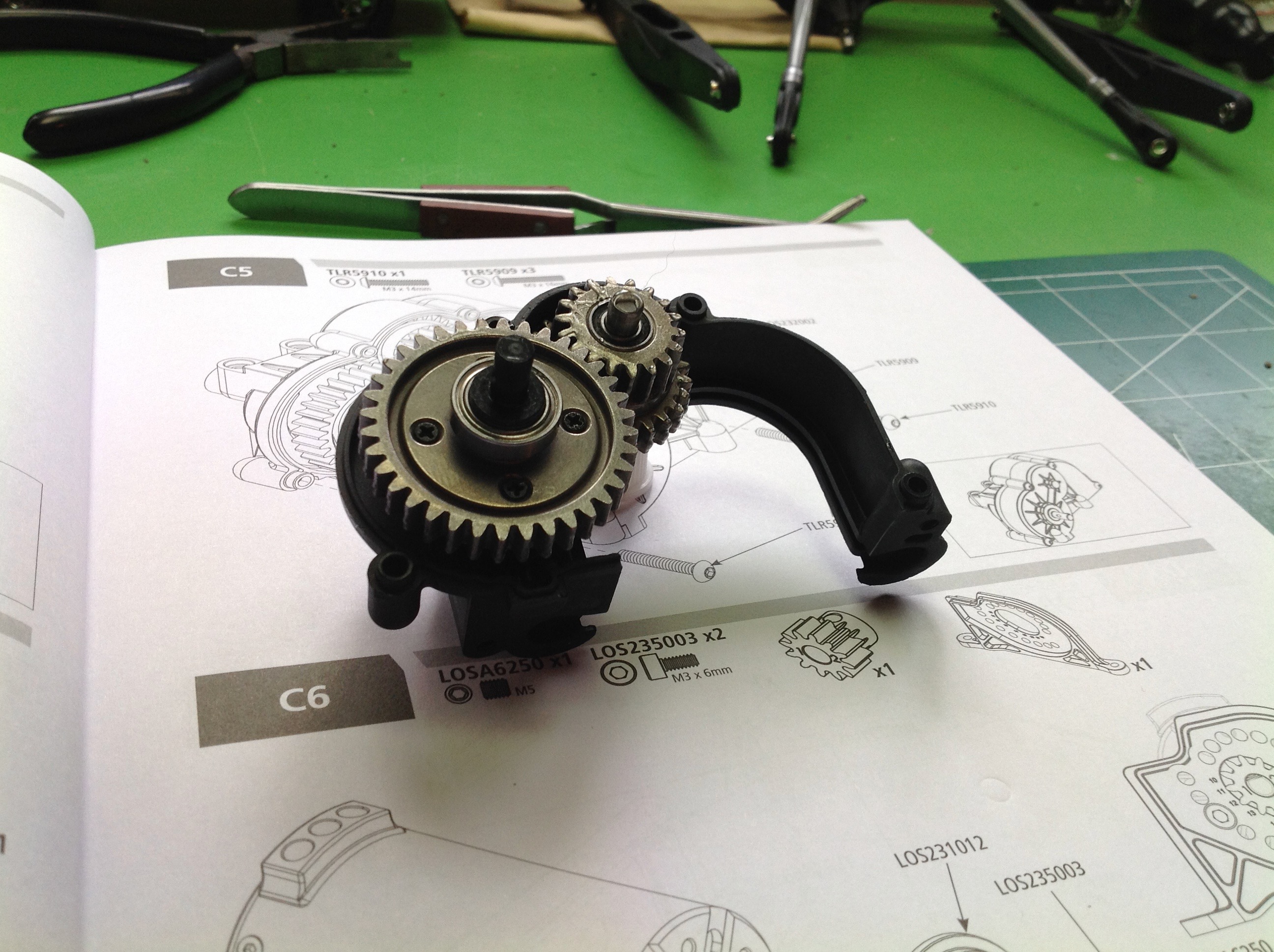
This model actually has a center differential which is pretty much like
the front one except that the ring gear is a spur instead of a
bevel. Lots more nice quality metal gears in this step.
The center differential is closed and then put into a gearbox with an intermediate gear set.
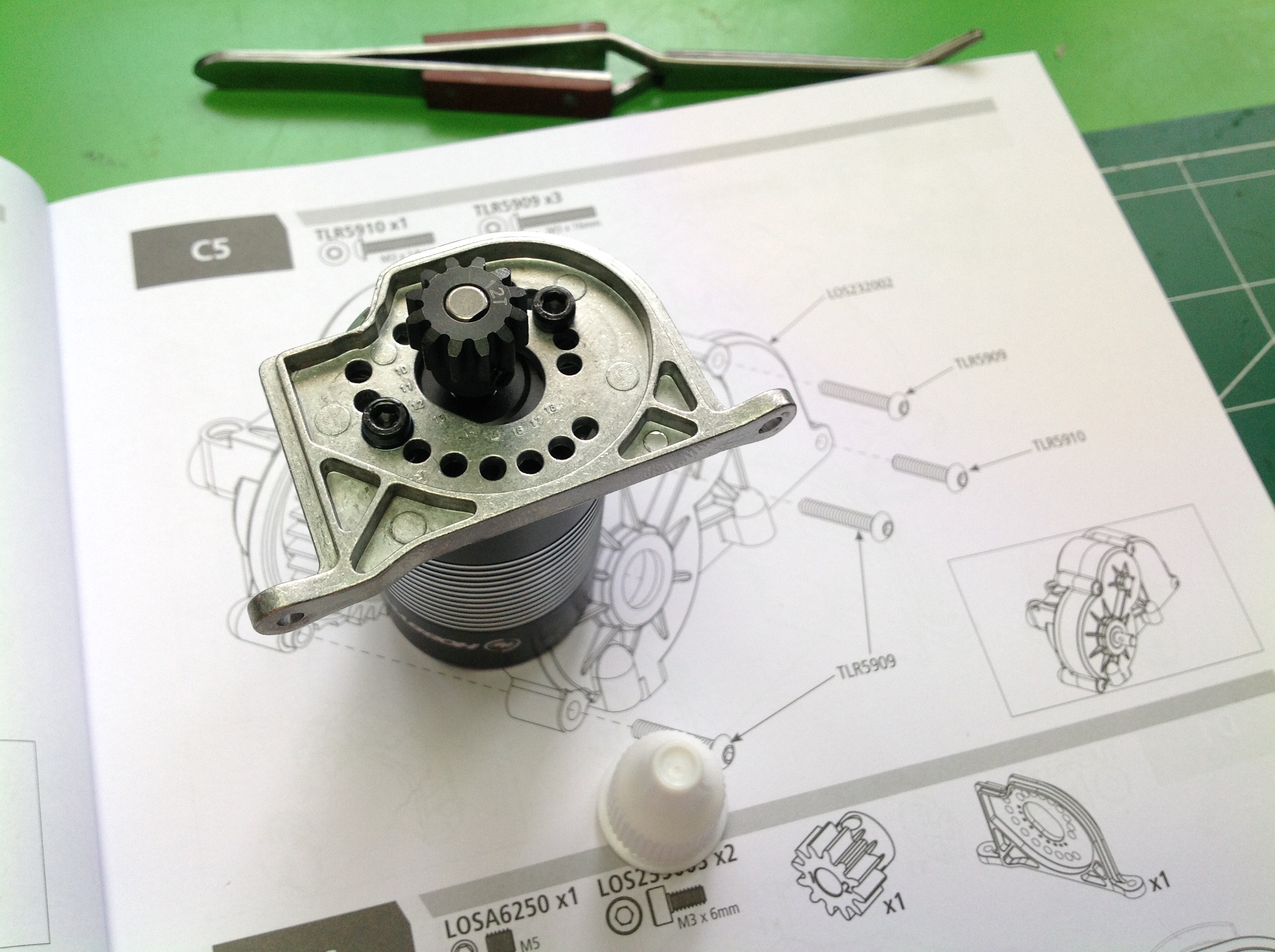
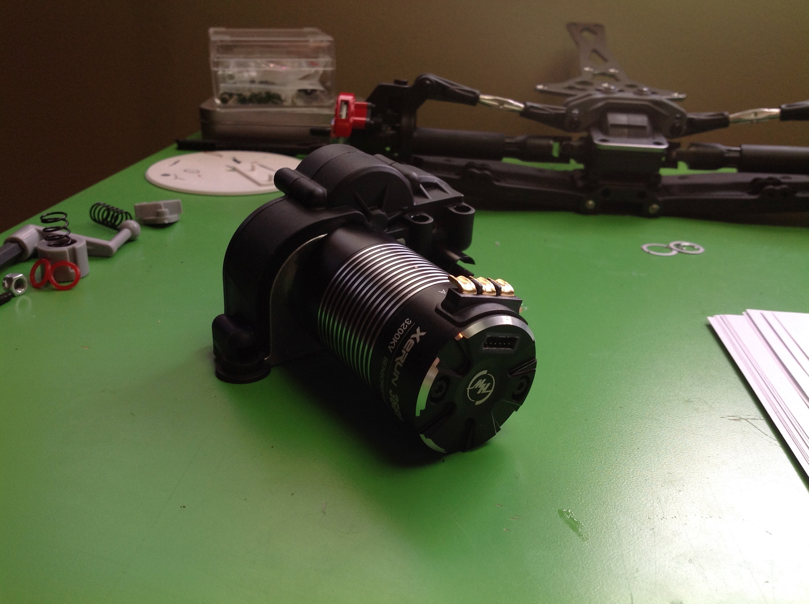
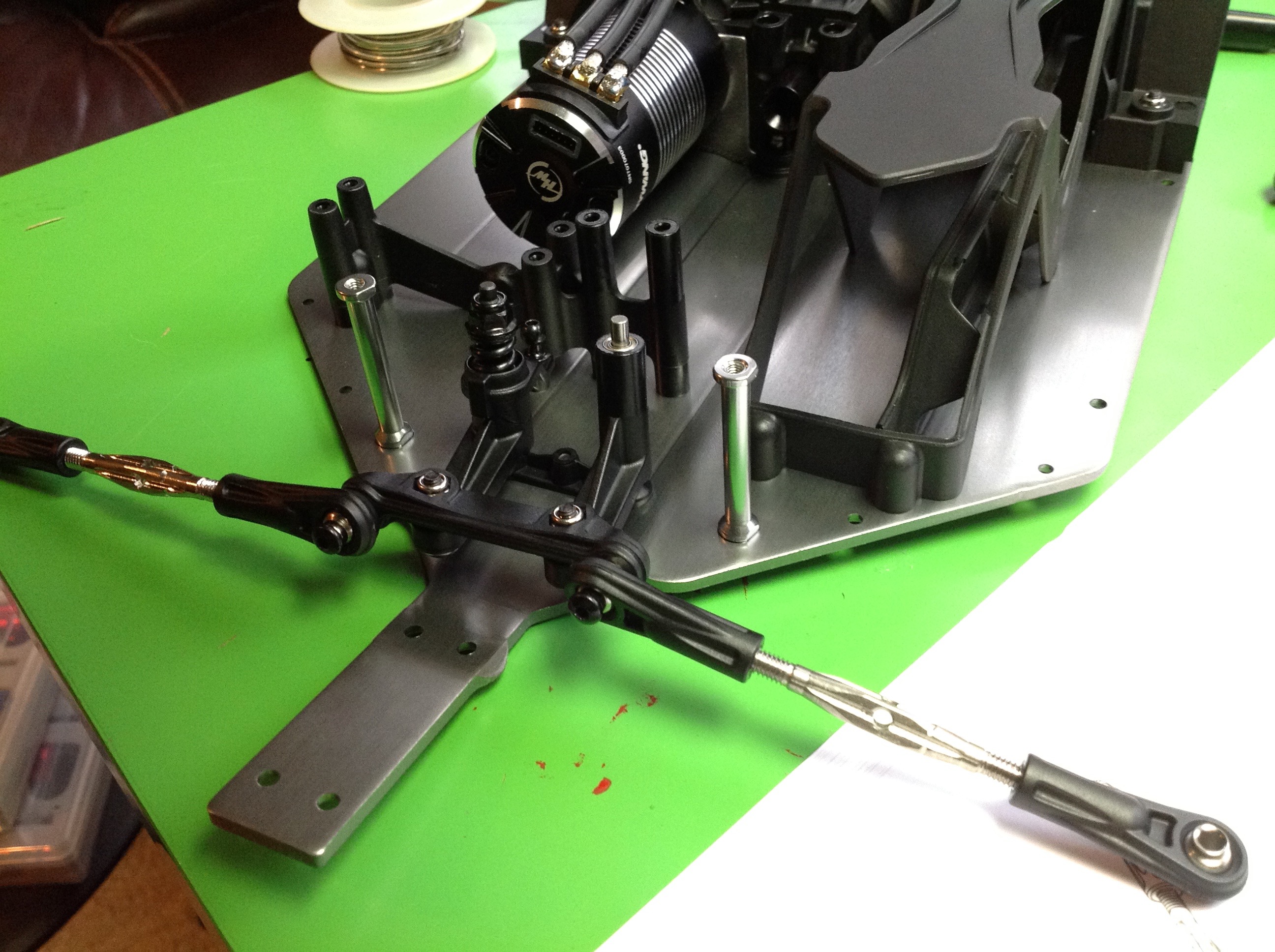
Now the motor is attached to the motor plate. This model uses a
determinant assembly here is which there is a different set of mounting
holes for each pinion size. The kit comes with a 12 tooth Mod 1
steel pinion. I chose a 3200 kV Hobbywing sensored brushless
motor.
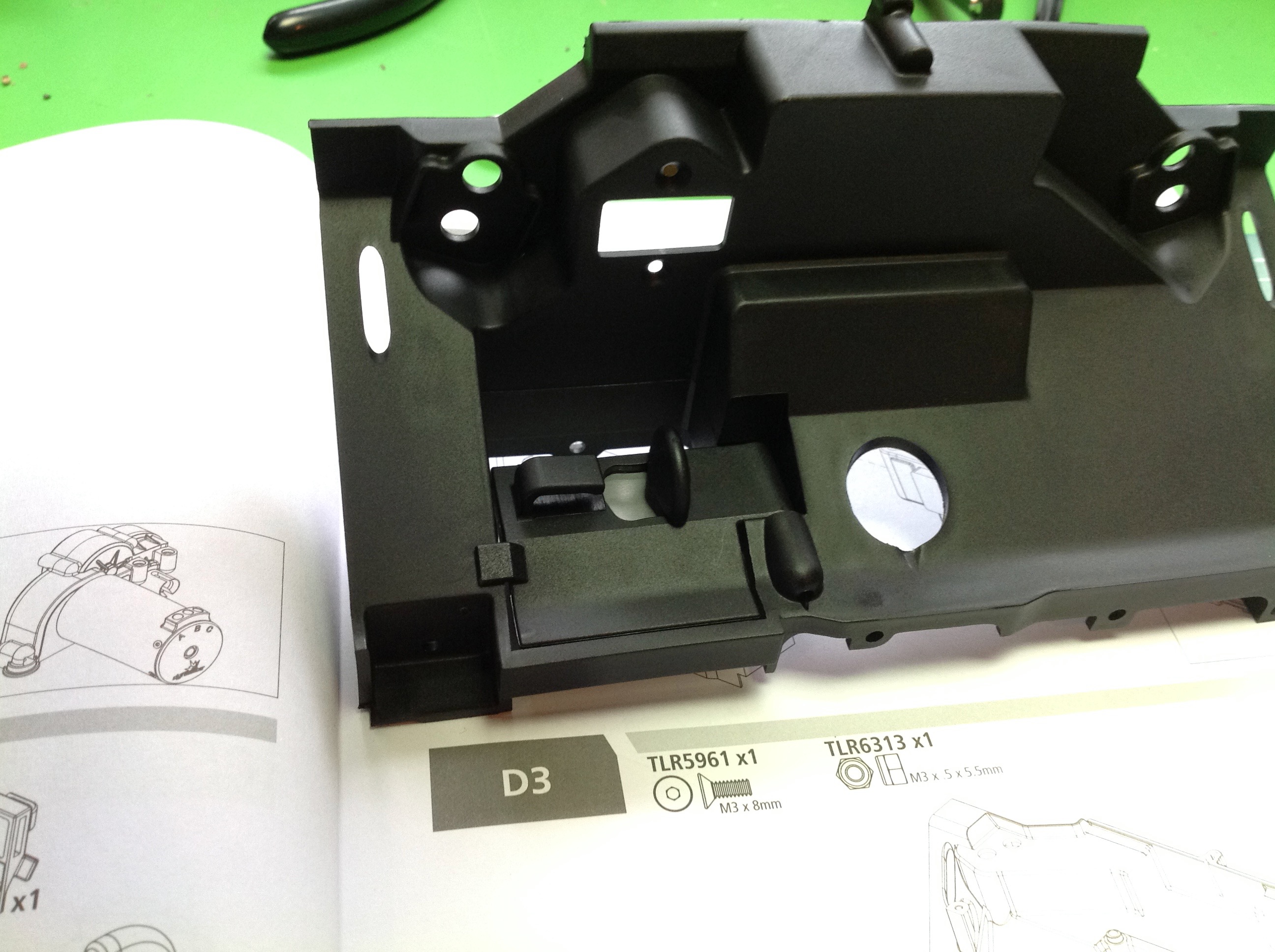
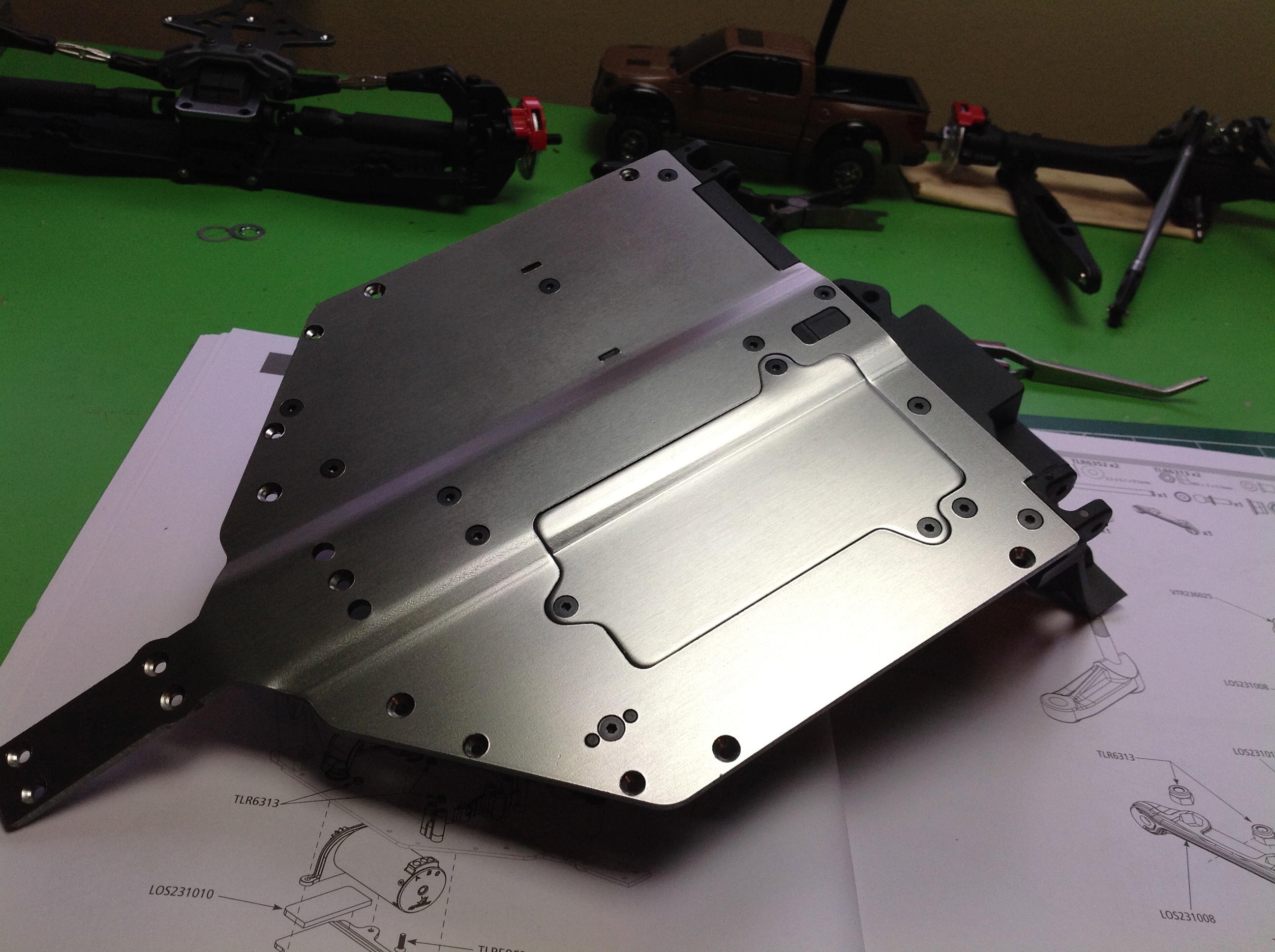
The left hand picture shows the battery hatch which sits under the
chassis facing aft. This will allow battery changes without
removing anything. The right hand image shows the lower chassis
plate along with the cage which will house the battery. Notice
that the lower plate is not flat. The bent areas will add a lot of
stiffness.
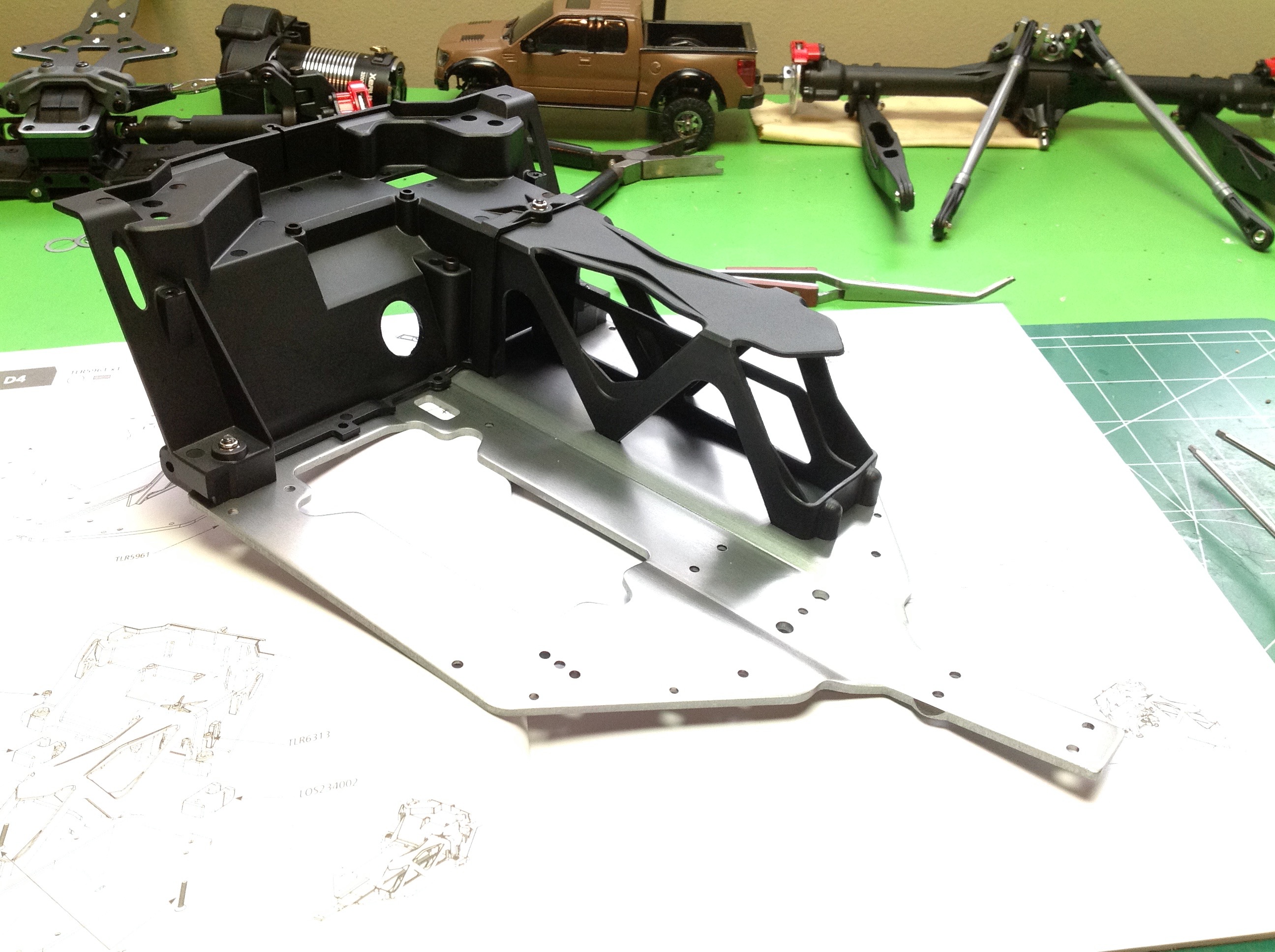
The gearbox is screwed to the chassis plate, but the motor is inserted
through a pocket from the bottom. This makes it possible to very
easily remove the motor without opening up the chassis (except for the
fact that I hard soldered all the wires). The shape of that
chassis plate reminds me of the bat plane.
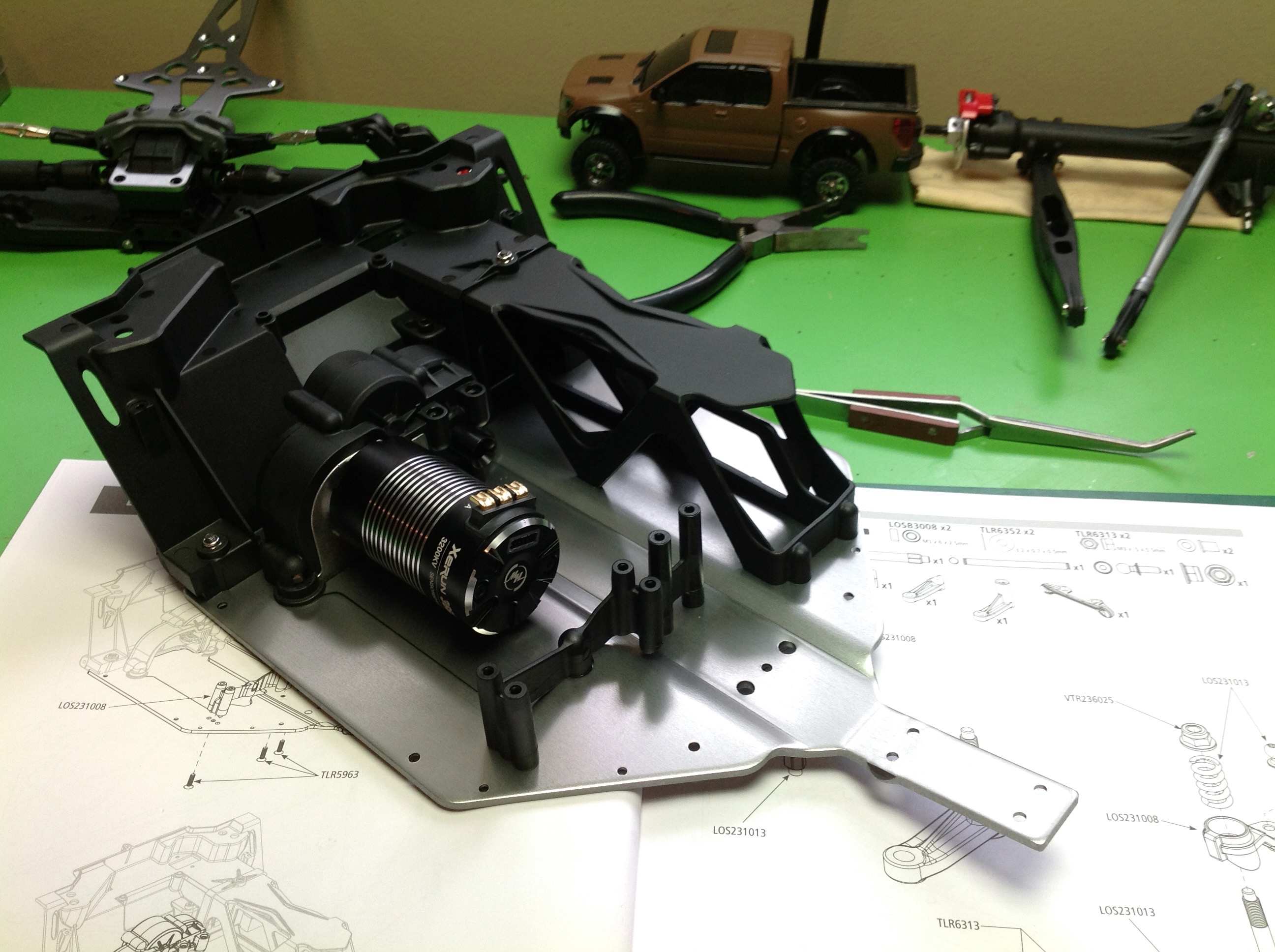
Now we'll build the steering mechanism. This is a dual bellcrank
system with full ball bearings. It will be captured between the
upper and lower chassis plates which makes it very strong but also very
hard to access later.
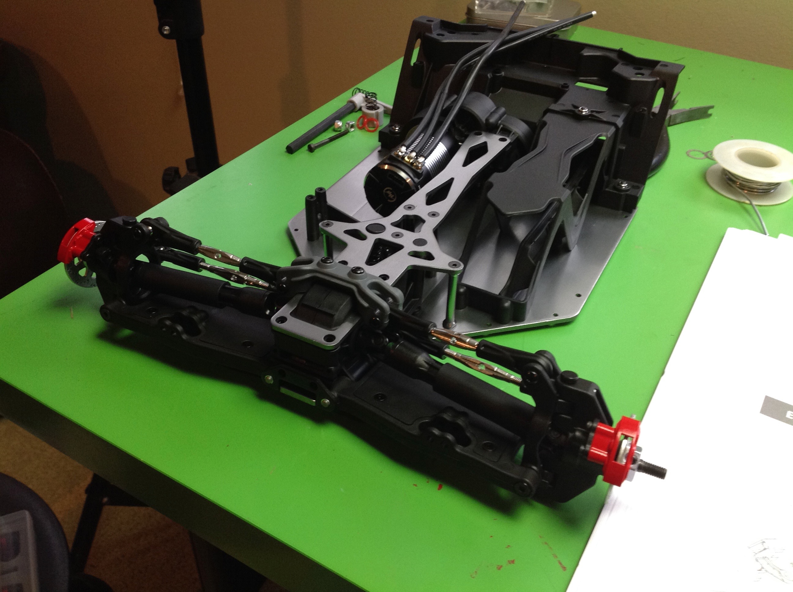
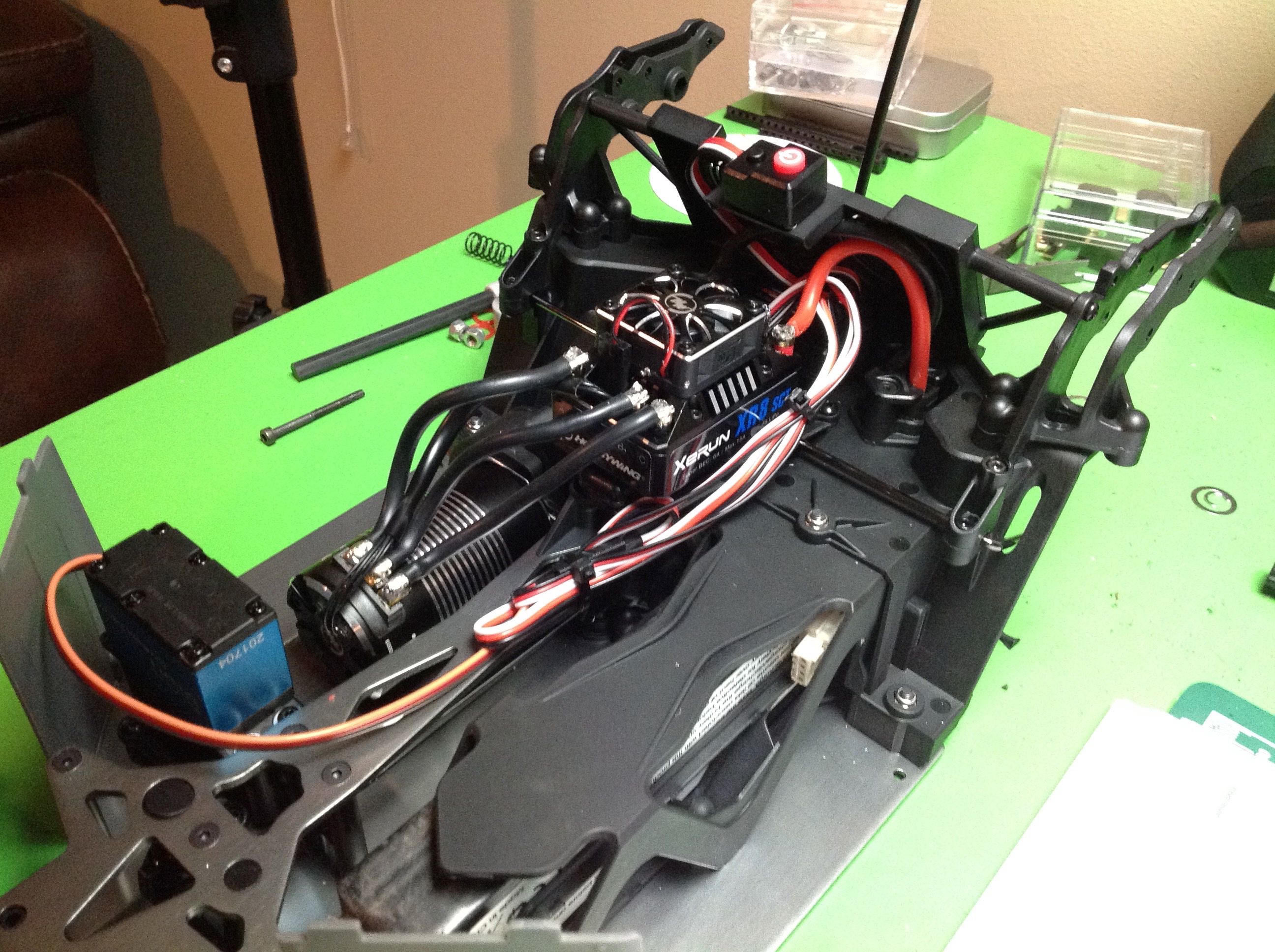
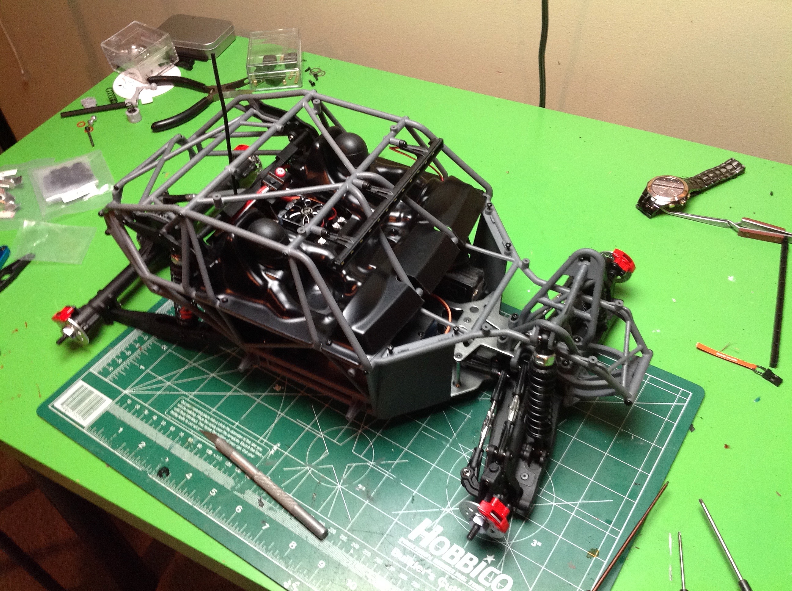
Finally the front and rear chassis sections are married together.
At this point the structure has become very strong even though the cage
is not installed yet. The second image shows the installation of
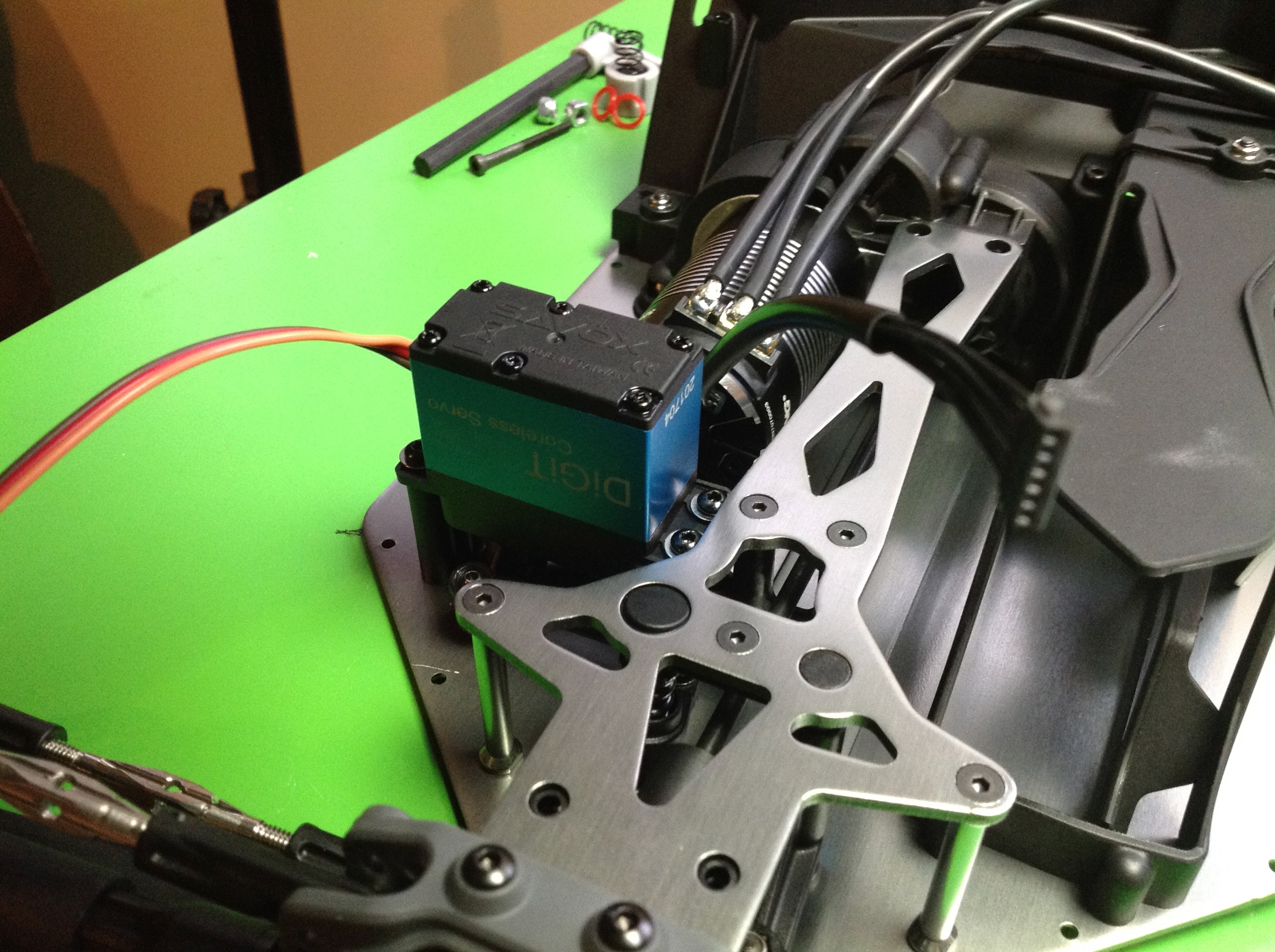
my waterproof servo. I am running this model on a 7.4V BEC to get
the most out of that servo.
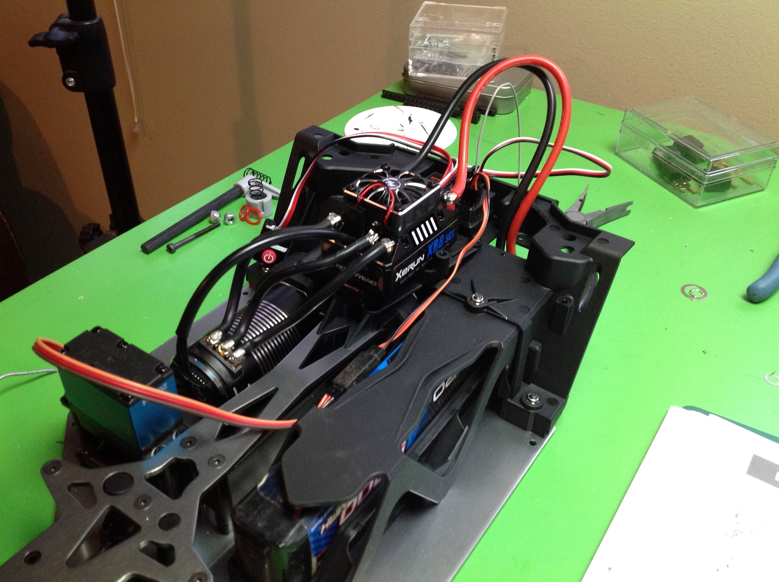
Time to do the wiring. This model is really designed as an RTR and
has provisions to screw in the stock speed controller. I am not
using the stock ESC, I am using a Hobbywing Xerun XR8 SCT. Luckily
it is about the same size so I was able to use the original location
but had to mount it with servo tape instead of screws. This is not
ideal since the wires end up providing some support that I'd rather
they didn't. The model is also designed to integrate the EC3
battery connector which I am not using. I was able to Dremel it
out and convert it to my standard Traxxas connectors.
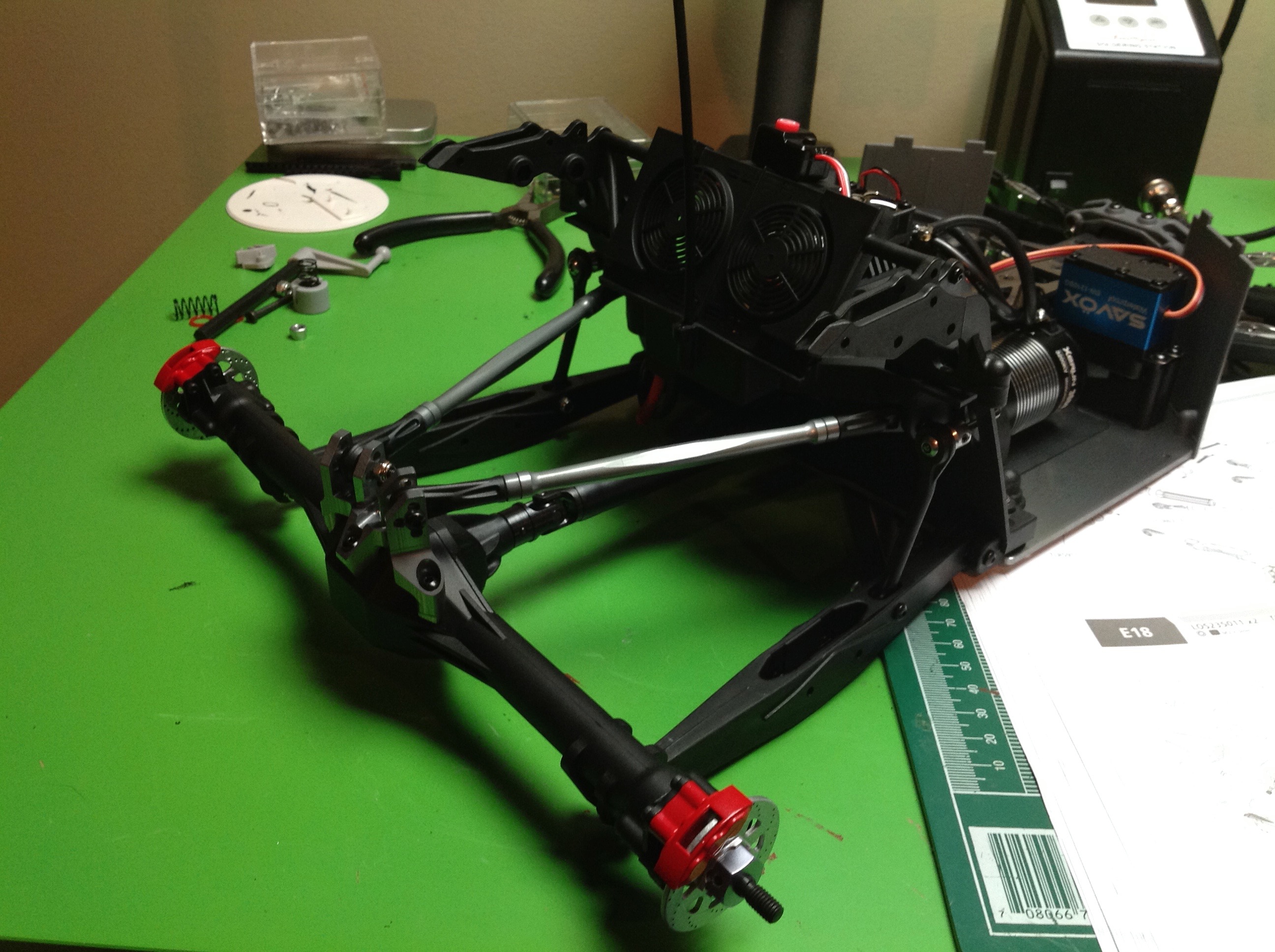
Attaching the rear axle is pretty simple. Just connect the four links and insert the drive shaft.
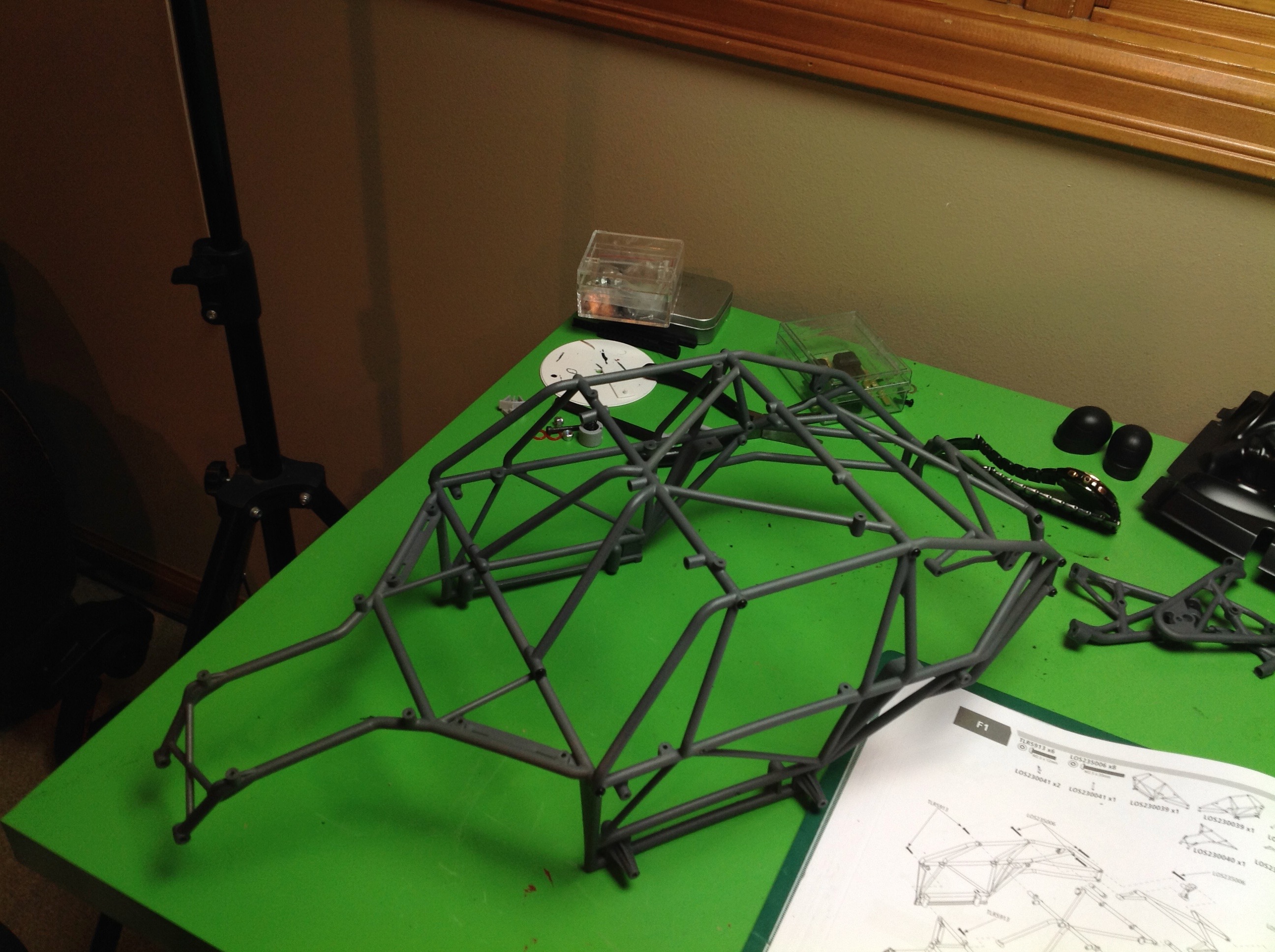
The cage is made up of 5 large sections bolted together along with some
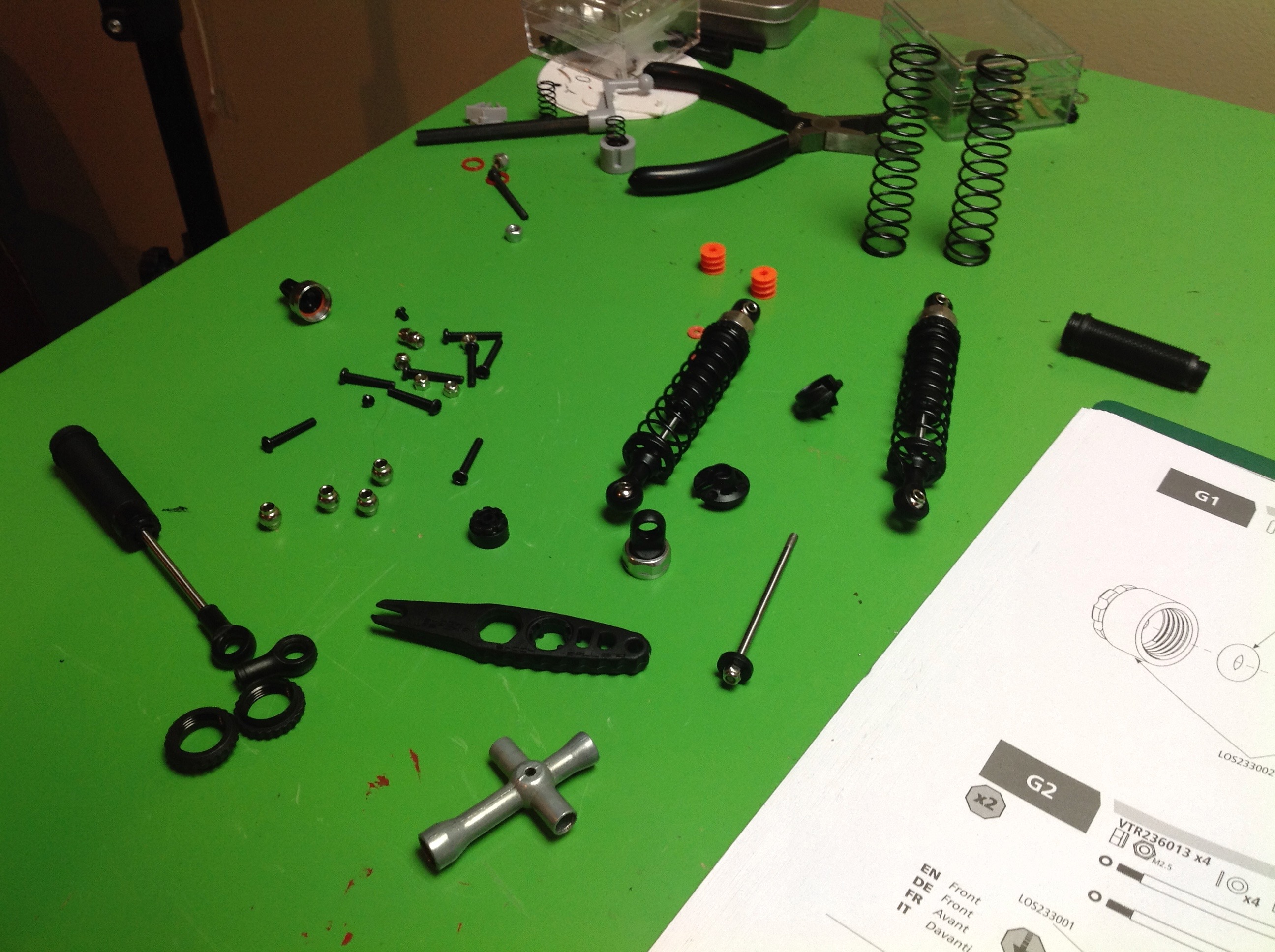
minor brackets. The fluid filled coil-over shocks are built
next. Only the upper cap collar is aluminum, the rest is plastic.
The cage attaches the chassis with a whole pile of screws, so you are
not going to want to take it off very often. However, if you want
to access pretty much anything inside then this is the only way.
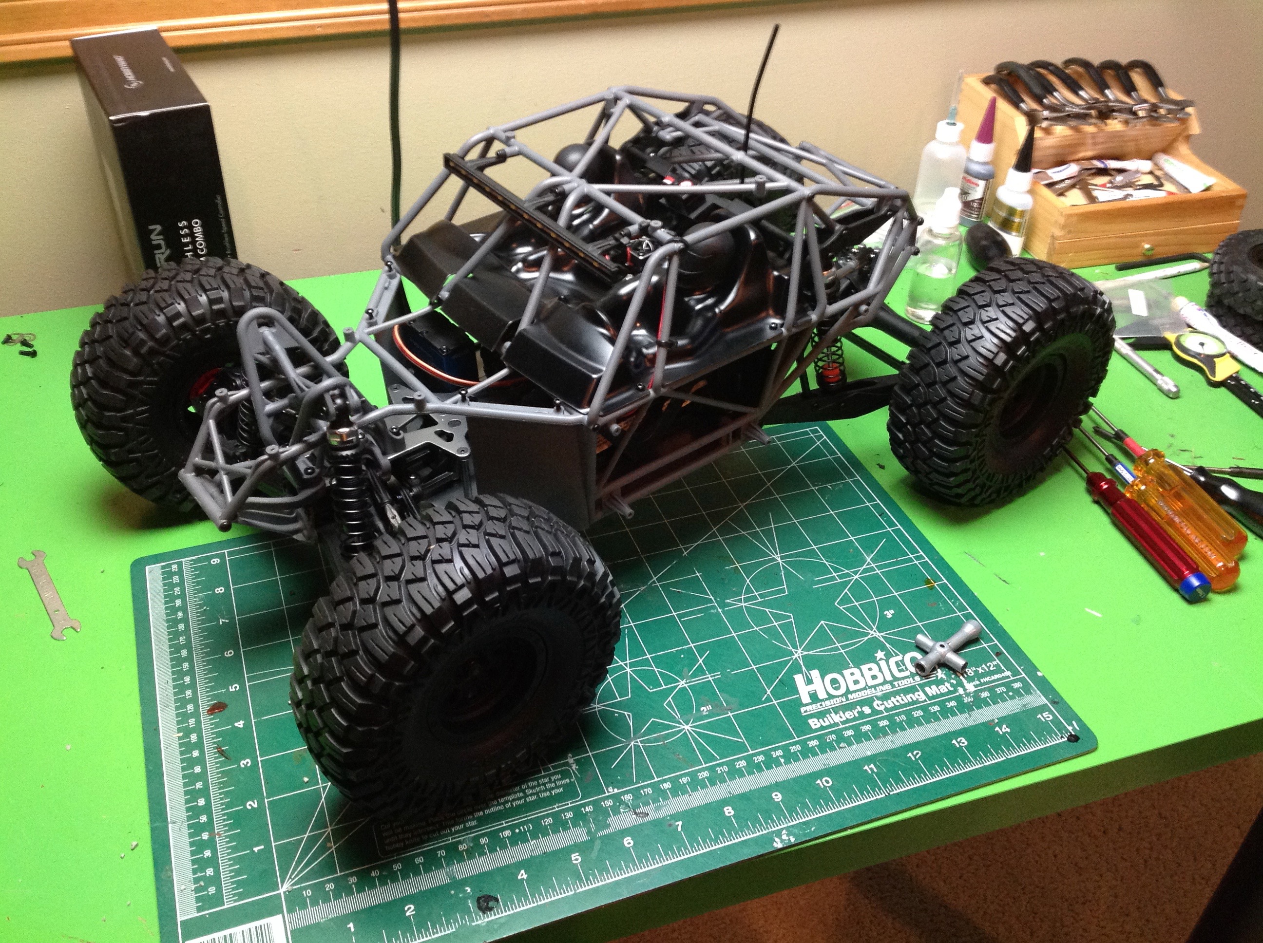
The hand image shows the completed model in stock form, but without the
body panels so you can see what's going on. There is a Lexan
driver piece which covers the internals, although the ESC
protrudes. The kit also came with a very nice LED light bar.
©2018 Eric Albrecht
 r
r