Axial SCX10 II Project
Page 1: Assembly
This build was early in my career when I didn't know what I was doing,
didn't know how to take pictures, and was generally winging it.
The fact that it worked so well anyway is a testament to the quality of
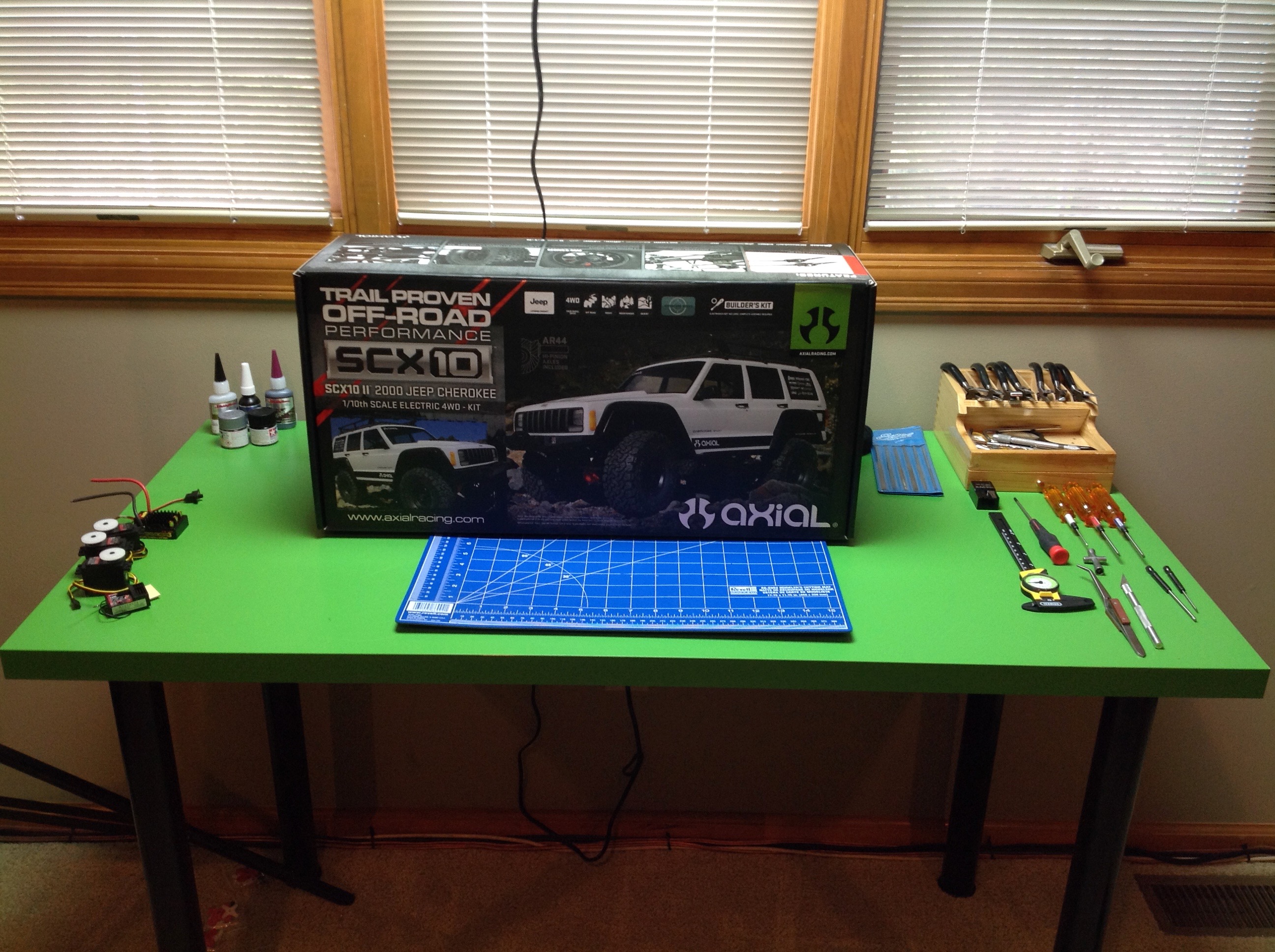
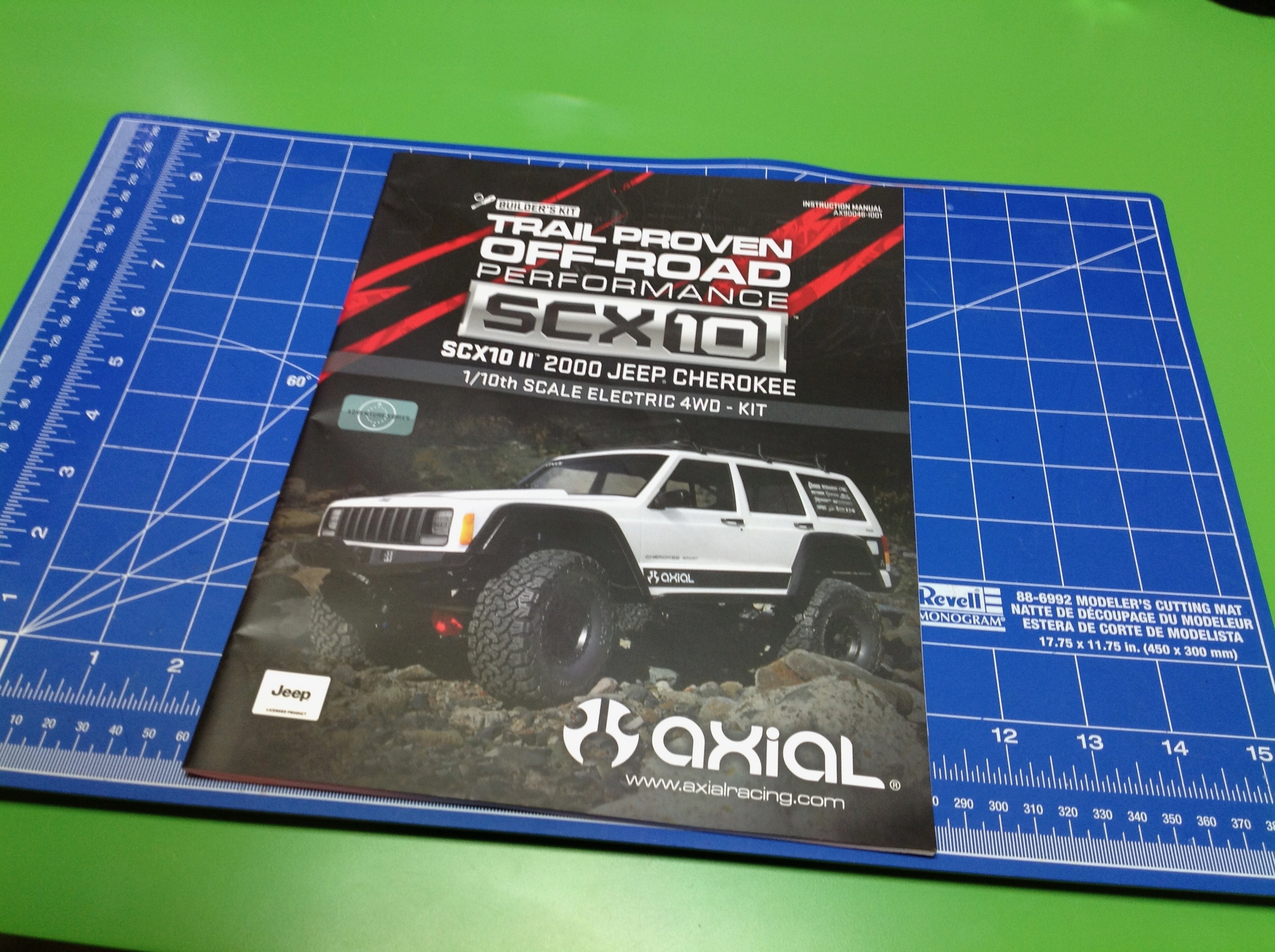
Axial's parts and instructions. Above you can see the box and the
nicely printed manual. The parts are packed in labelled bags for
ease of building.
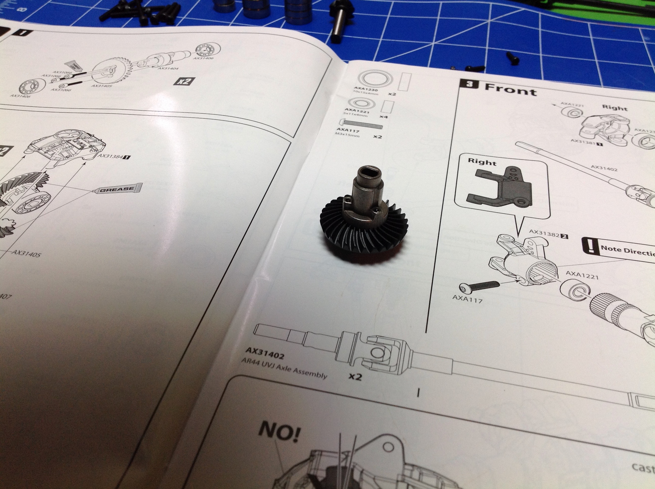
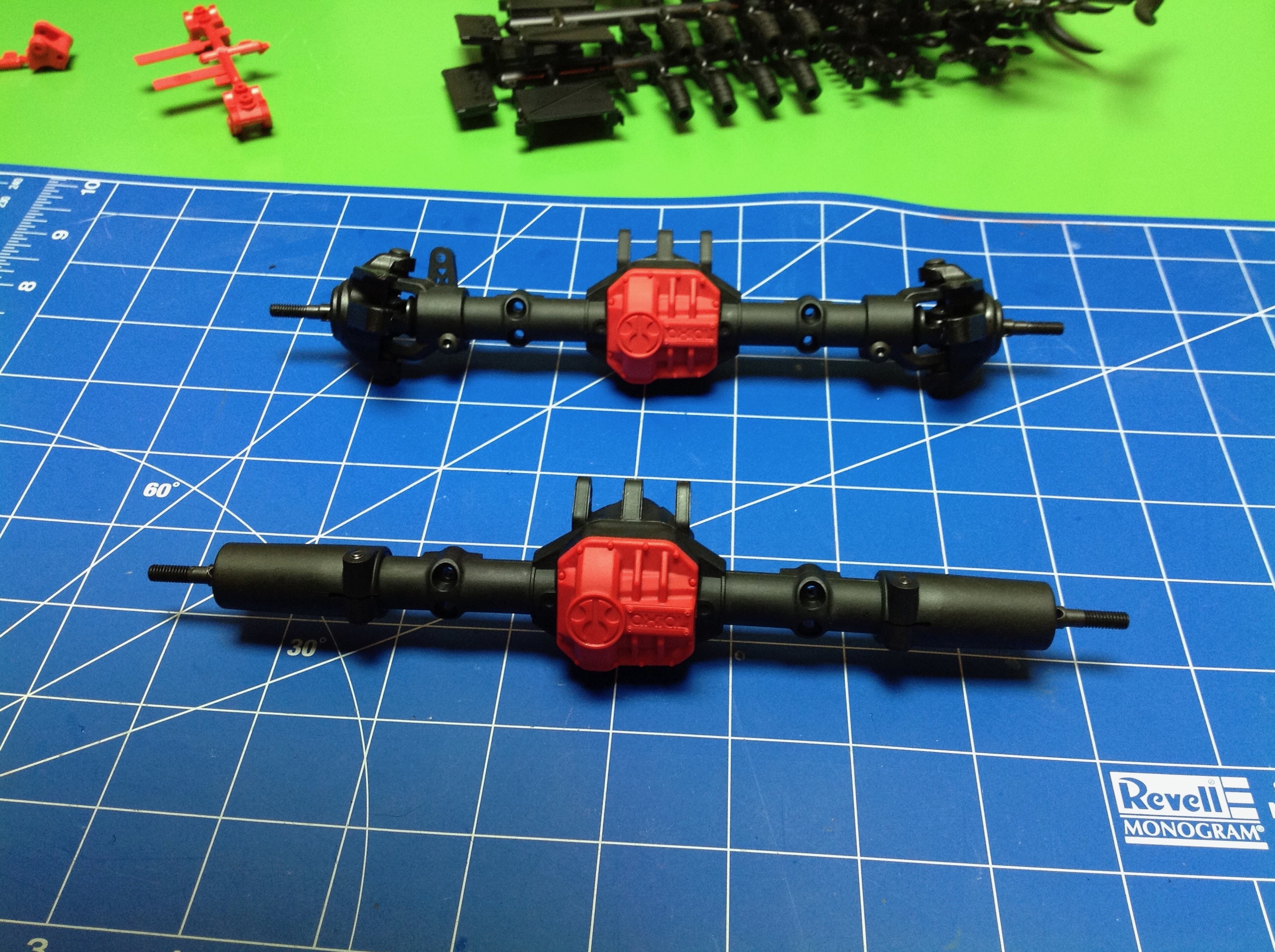
Being someone who works with gears for a living, I was really pleased to
see these spiral cut hypoid gears. This is the differential spool
ring gear. With this gear configuration, the pinion exits above
the axle centerline.
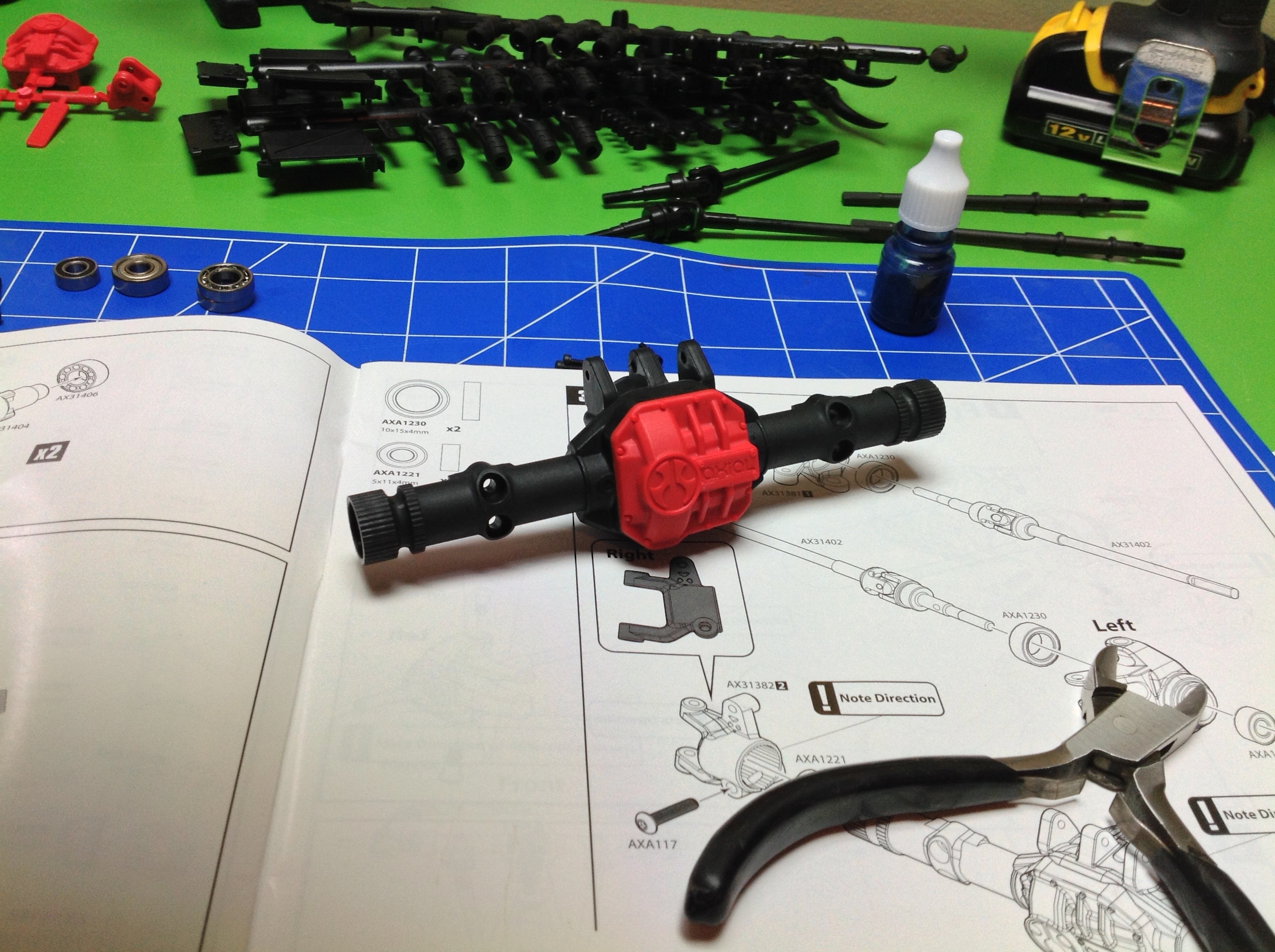
The axles are pretty easy to put together. The center section of
the front and rear axles is identical, but when you install the ends
they become unique. The rear uses straight ends and the front gets
C-hubs and steering knuckles. The kit includes full ball
bearings. Axles are steel.
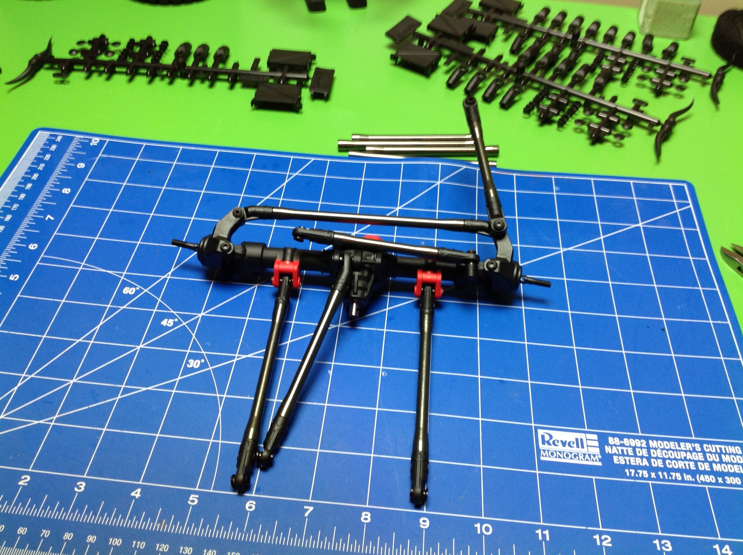
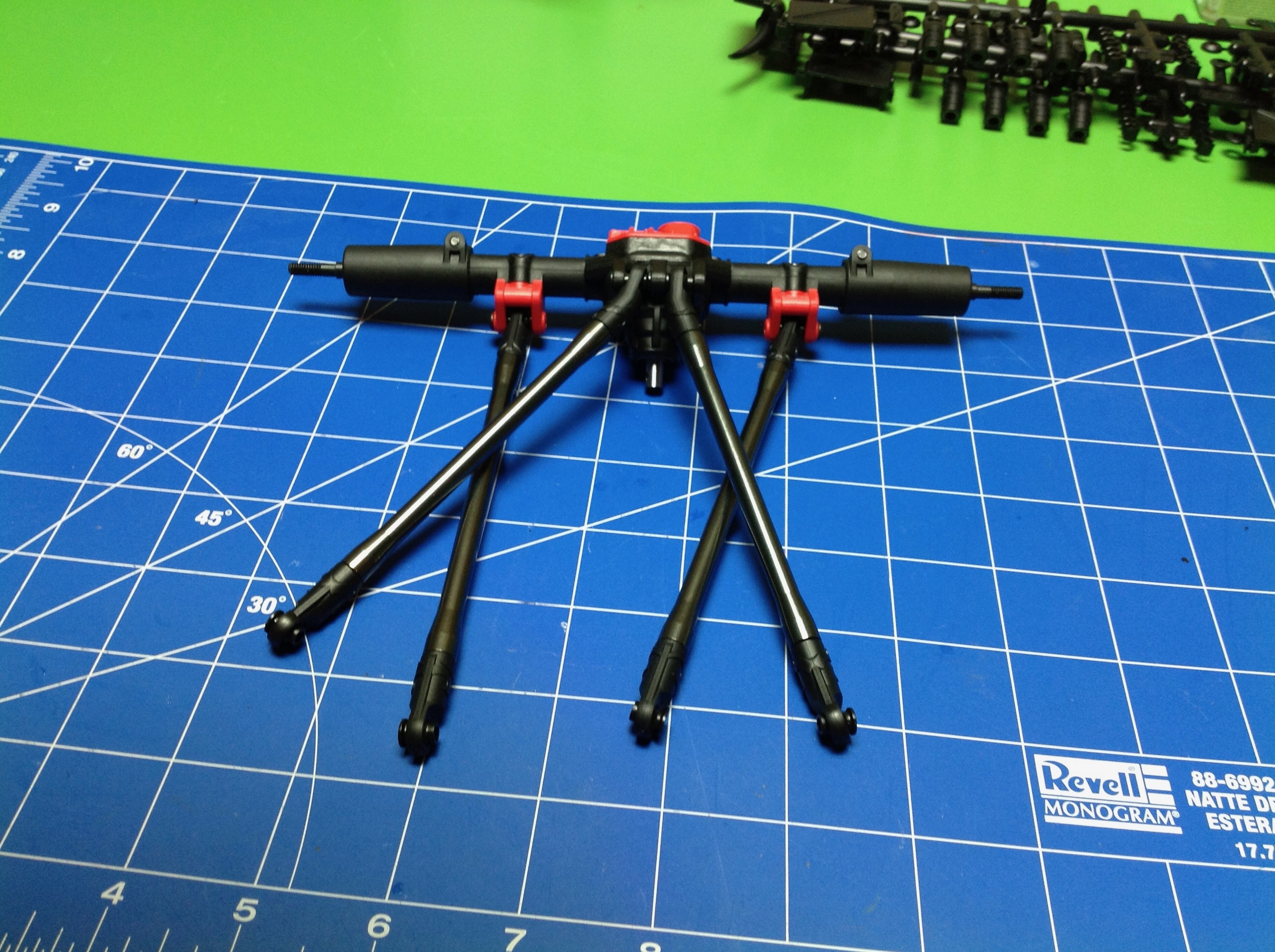
The front suspension uses a total of 6 links. The primary support
is a 3-link type. Then there's the servo link which connects to
the servo and a panhard bar which reacts the lateral forces from
steering. Finally there's the steering link which connects the
right and left hubs. In the rear we get a standard 4-link setup.
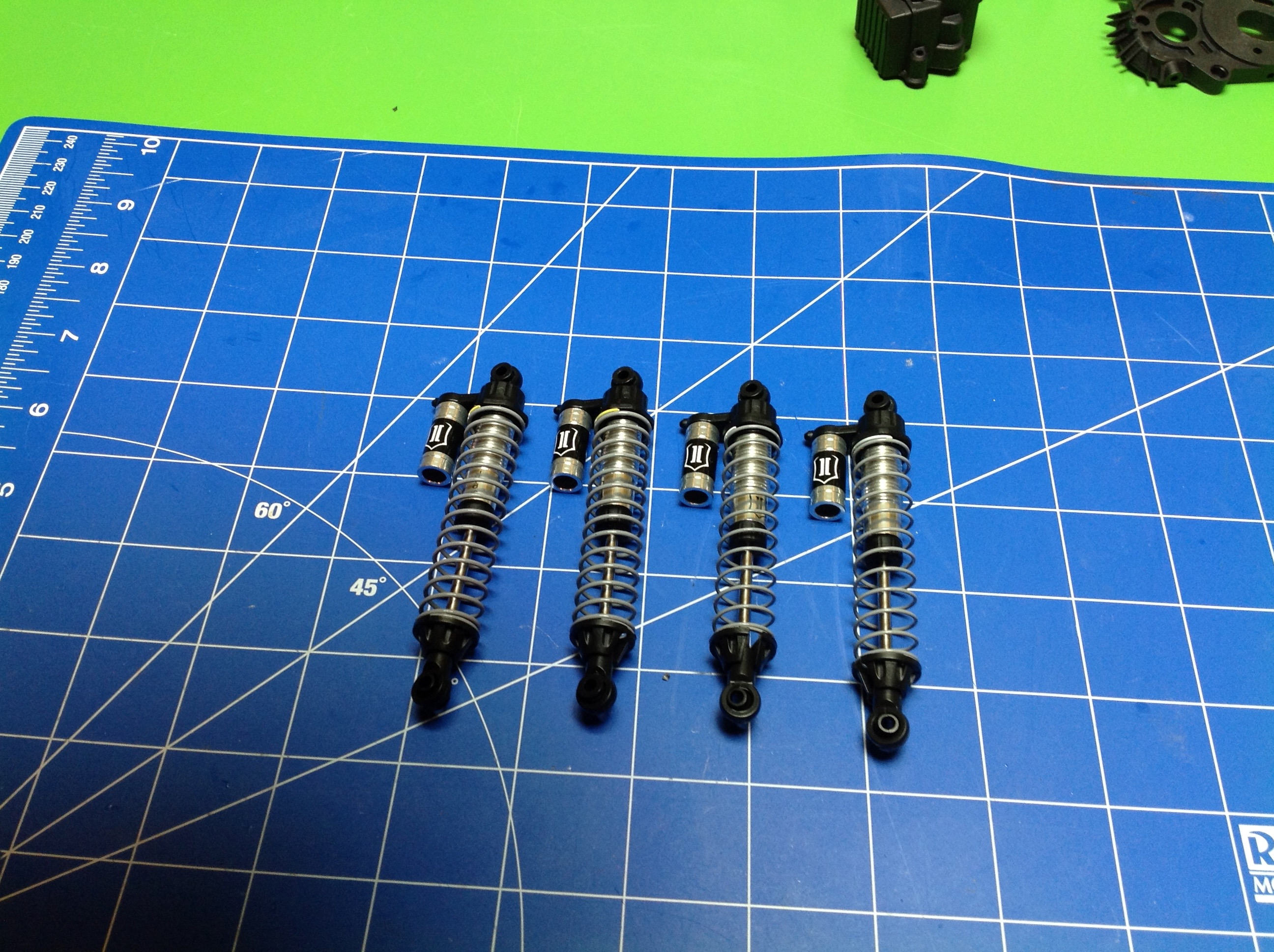
The shocks have aluminum bodies and are oil filled. At the time,
these were the first I'd built. The reservoirs you see are not
functional but are just there for appearance. The diameter of
these shocks is not very large but they supply plenty of damping for
this slow model and look scale while doing it.
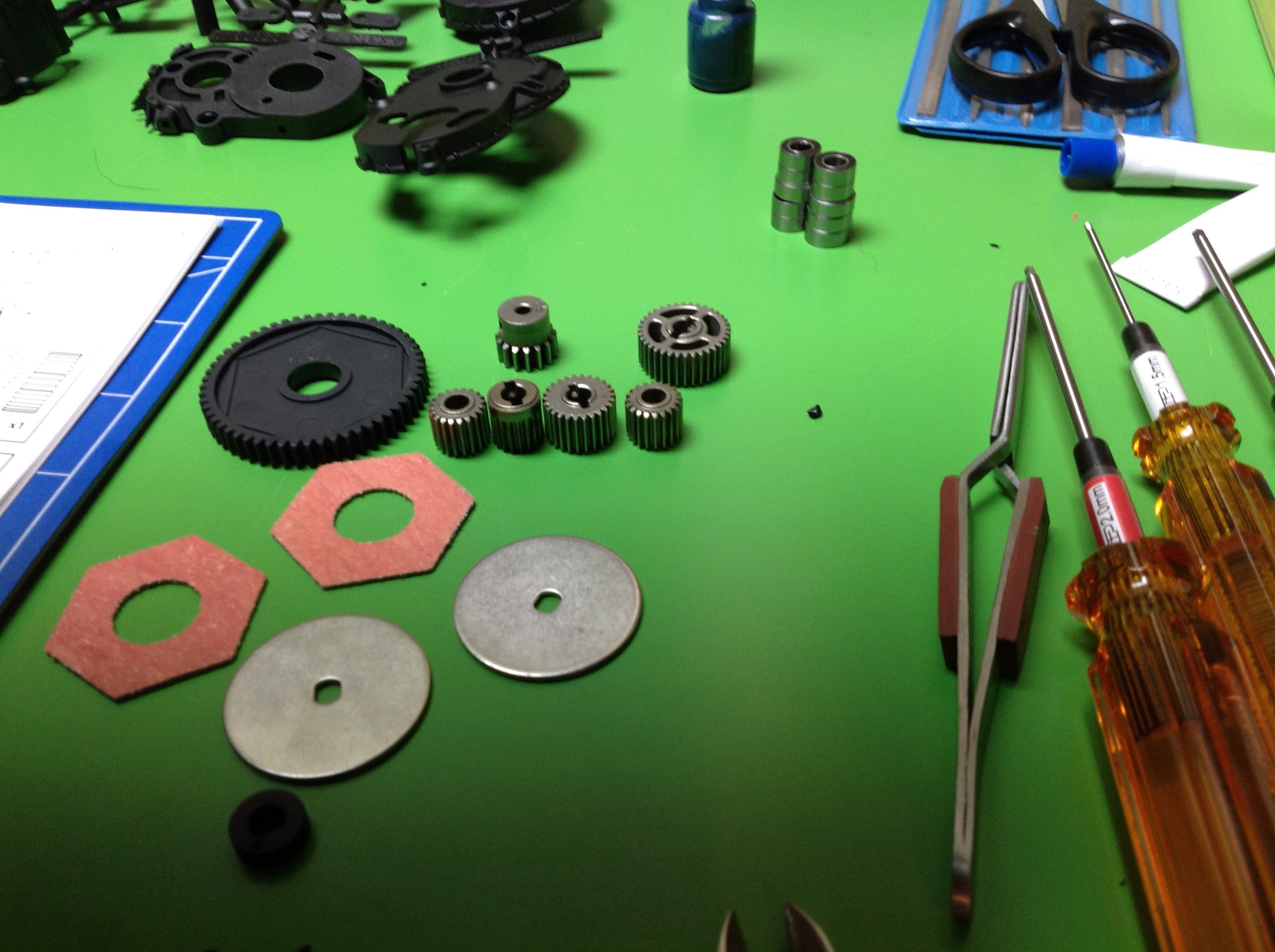
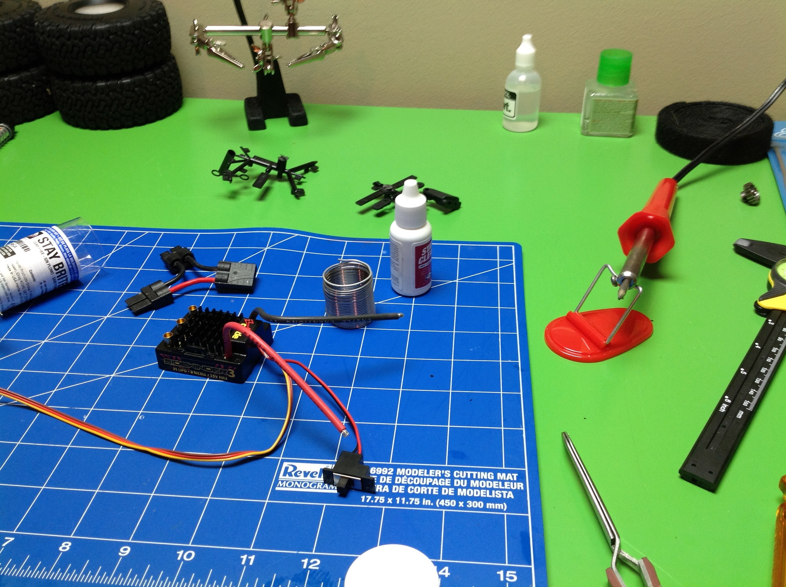
In the left hand image you see the parts for the transmission and
slipper clutch. There are a pile of nice metal gears. The
spur is plastic and uses a slipper with two friction discs. On the
right you can see the pathetic soldering equipment I had at the
time. It took me a long time to get anything connected and it was
done badly. I got a chance to go back and fix this much later.
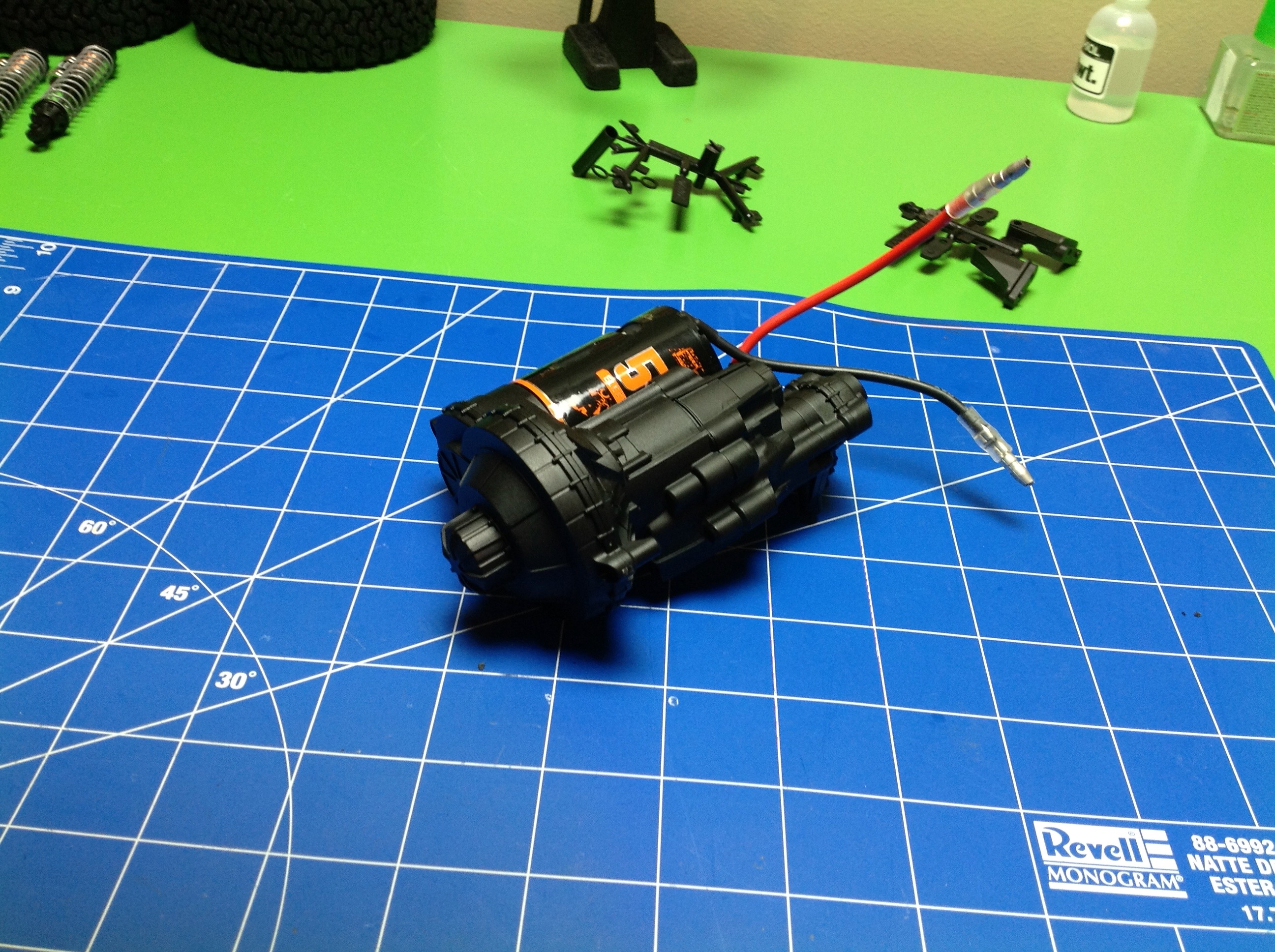
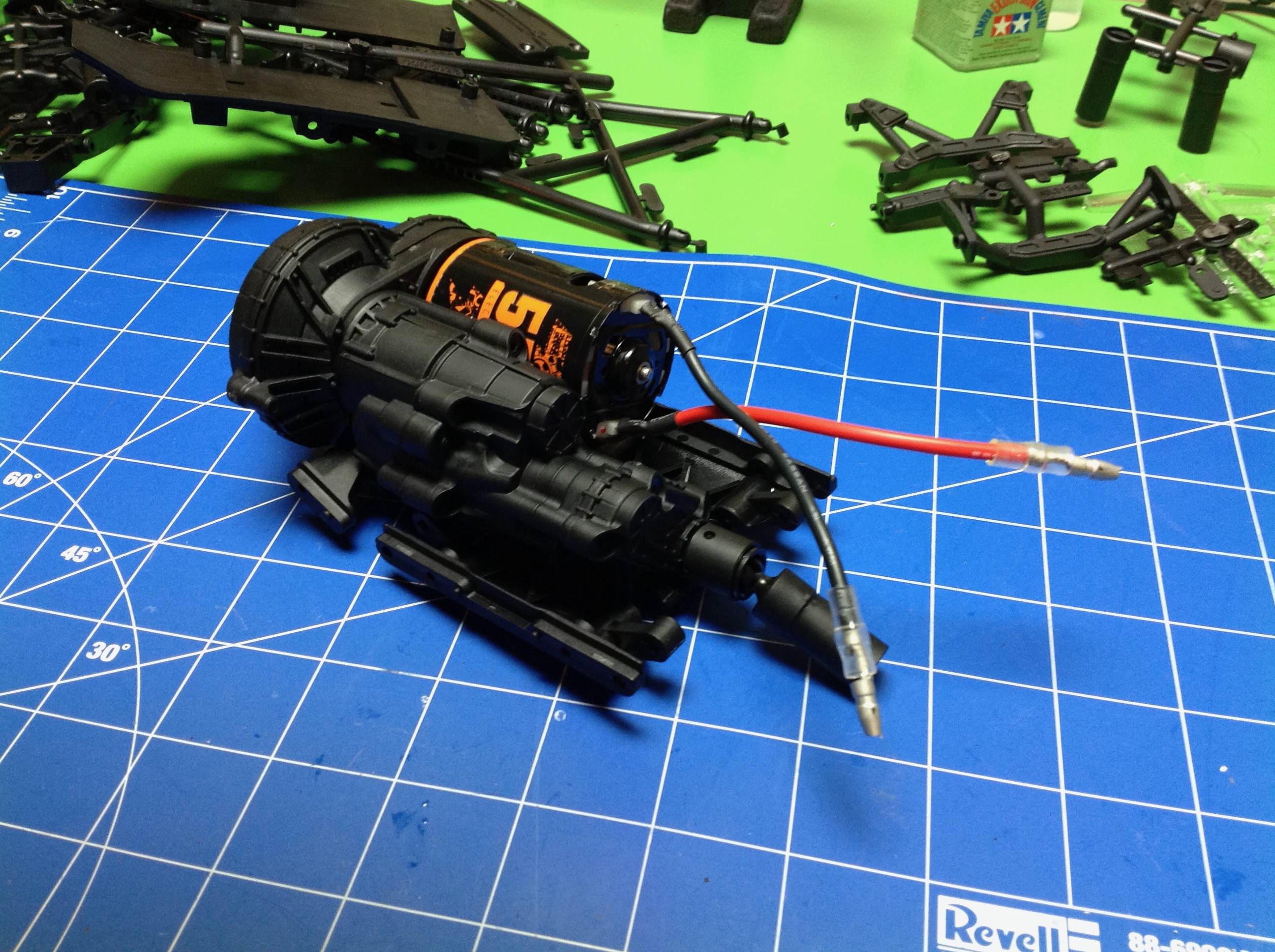
Here's the nice big transmission gearbox and the attached transfer
case. The motor you see is just a placeholder; I ended up swapping
it for a 35 turn Integy before I was done. This motor went in a
tractor truck.
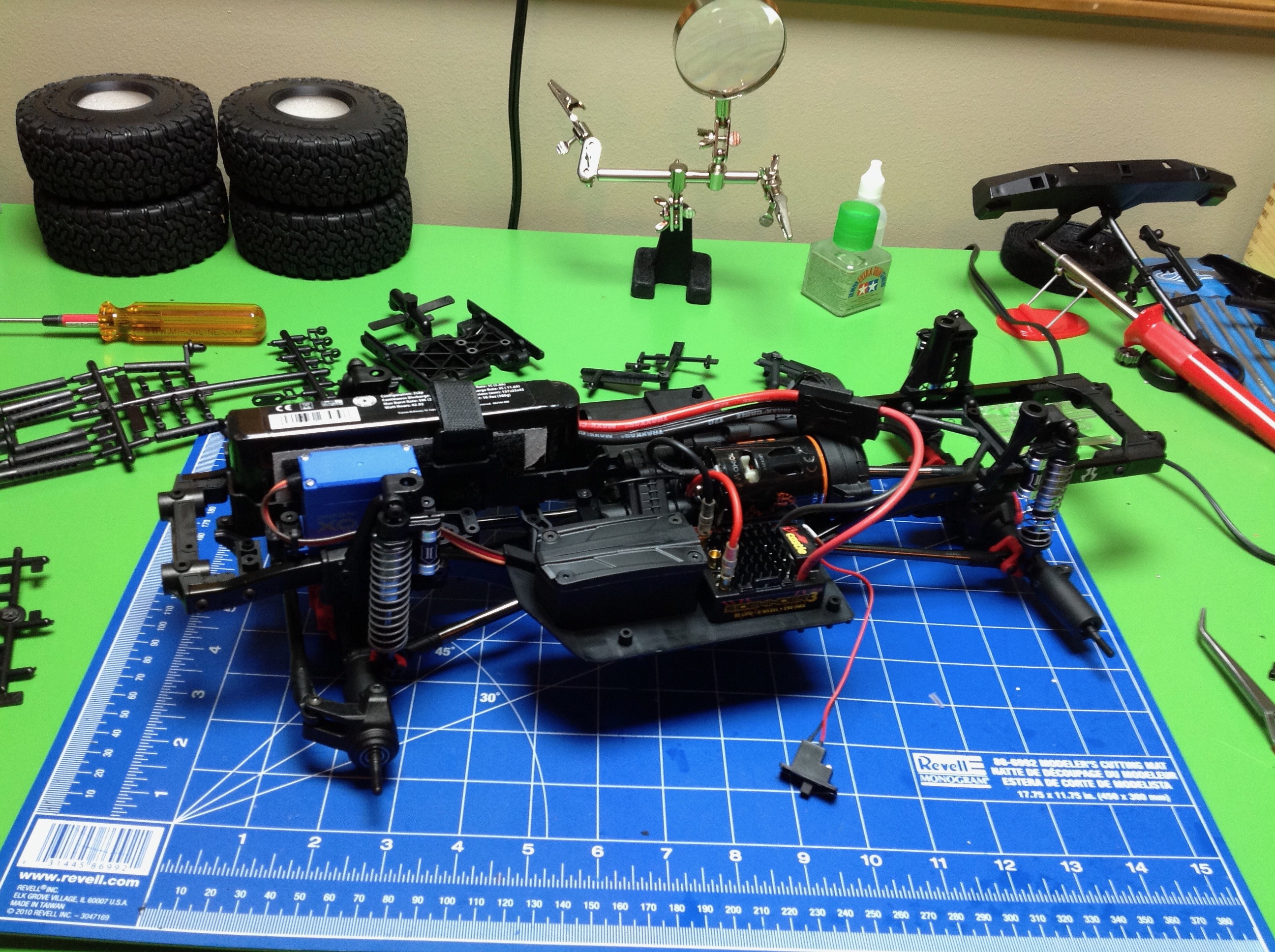
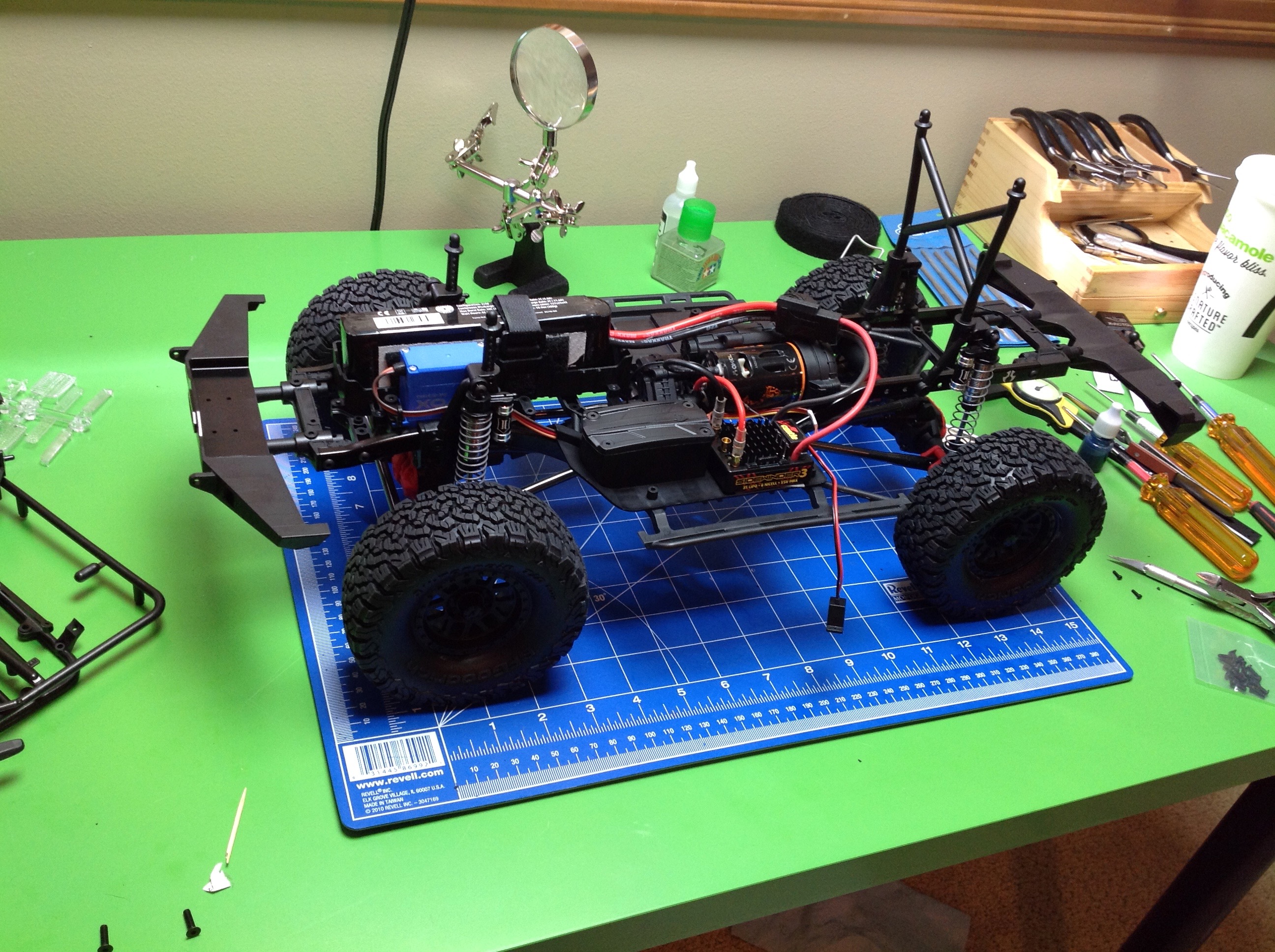
Now everything is stuck together. I skipped taking pictures for a
few steps. I never showed the frame going together, for
example. In any case, here you see the rolling chassis. The
battery is located in the front over the axle along with the steering
servo. The electronics box is sealed, and there are convenient
clips to help with routing the wiring neatly. Last step is the
bumpers and the tires. Bumpers are plastic but quite sturdy and
with provisions for adding a winch. You can see the tall body
mount tower in the back.
©2018 Eric Albrecht