Axial SCX10 III Project
Page 1: Chassis Assembly
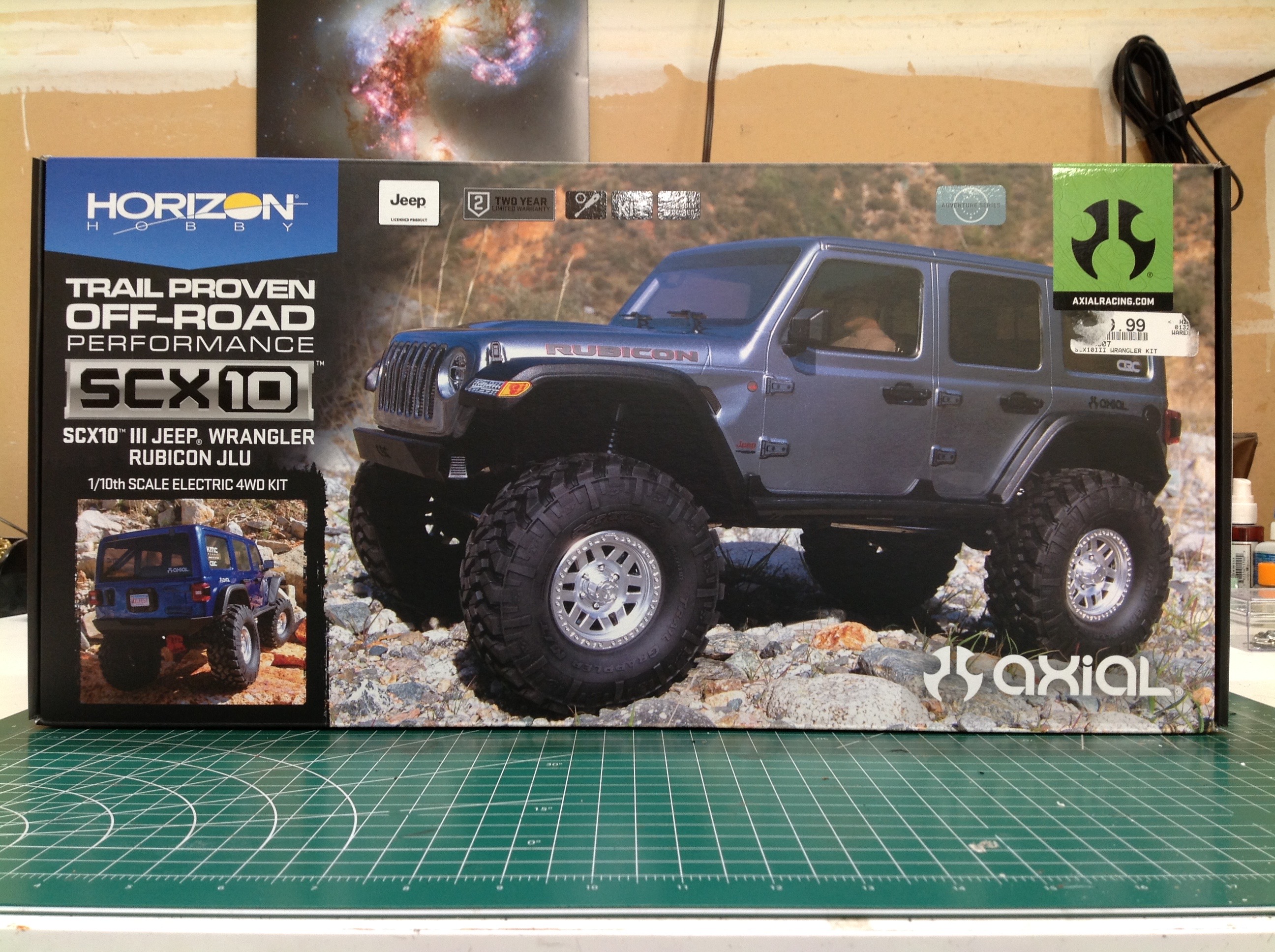
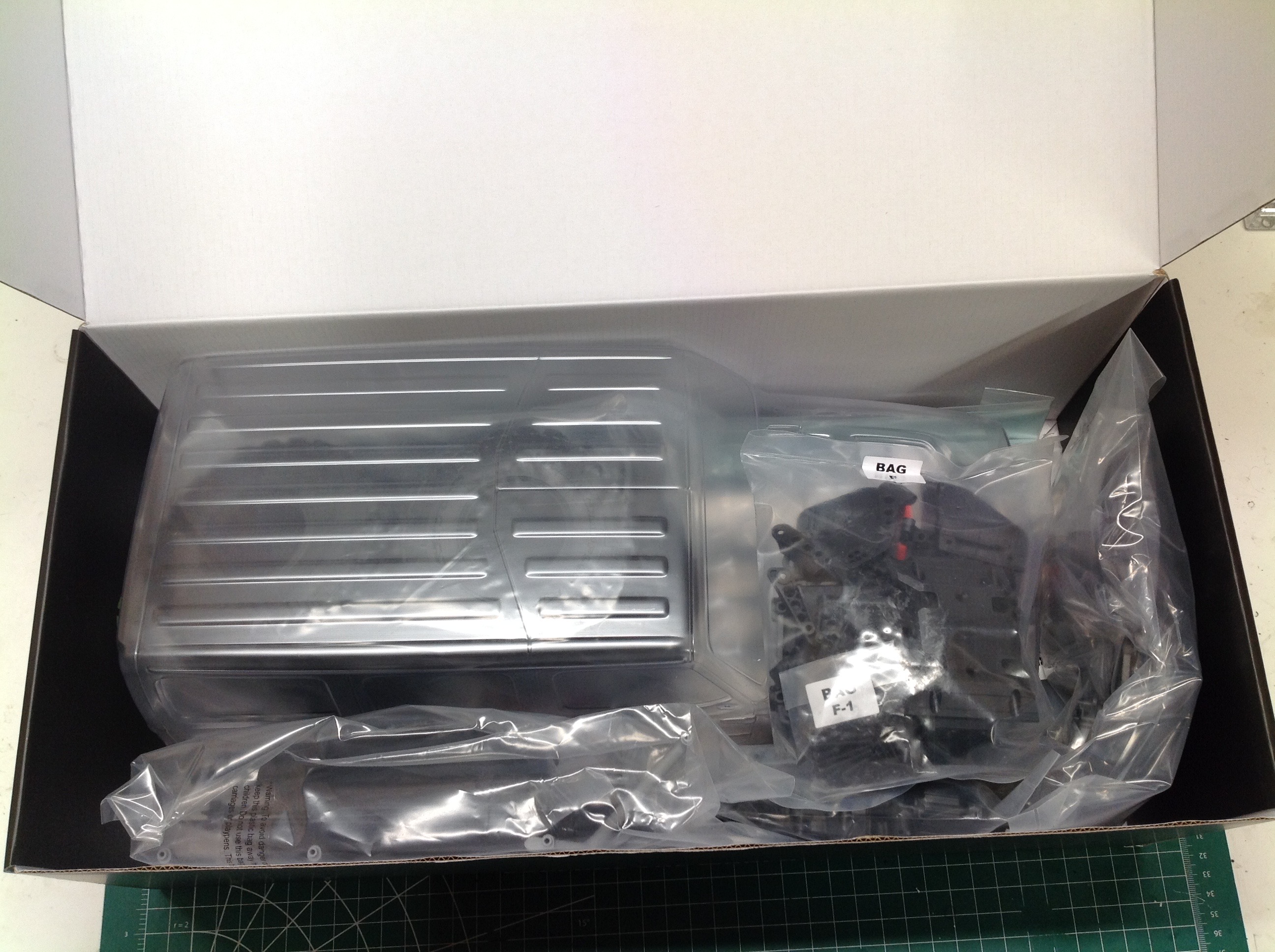
The Rubicon comes in a modestly sized box which is mostly filled by the
body alone. The majority of the parts sit underneath it or on the
hood.
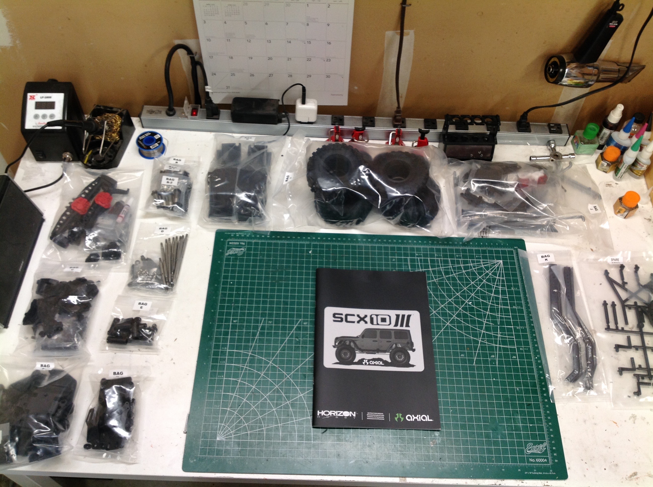
The image on the left shows all of the parts arranged on my build
table. The bags are arranged in labelled groups with each group
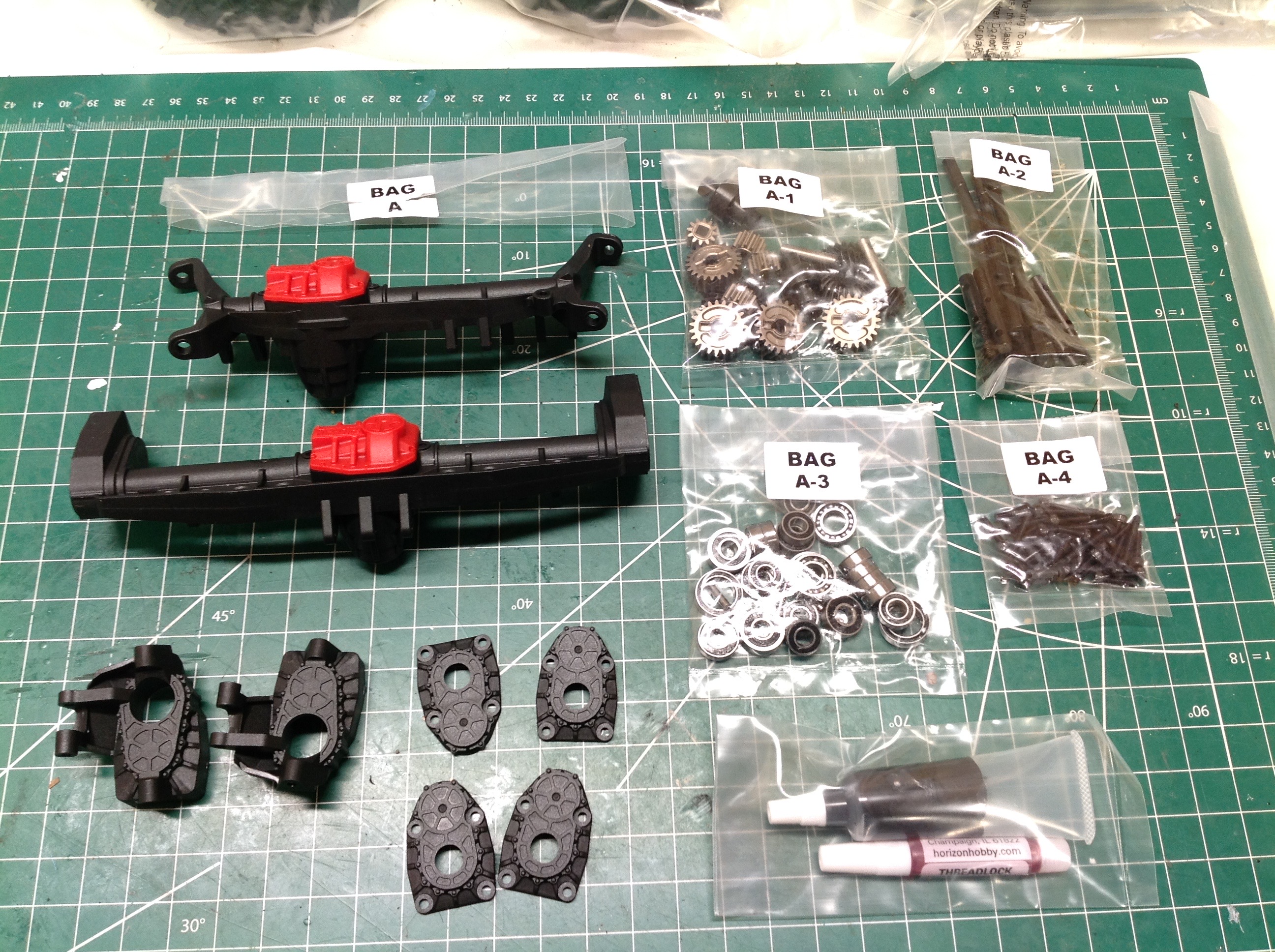
covering a logical series of steps. Bag A contains 4 sub-bags with
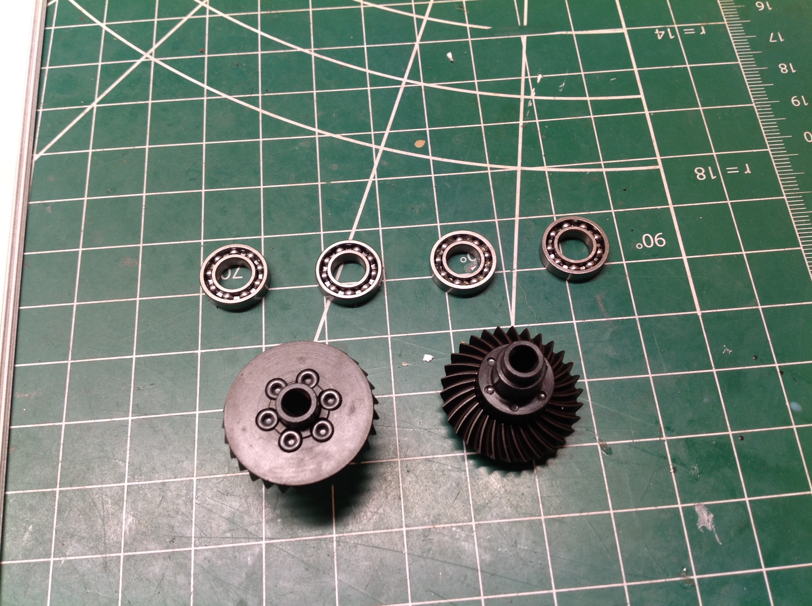
the parts needed to build the axles as shown on the right. Note
the full ball bearings included as well as the grease and thread lock.
The build begins by attaching the differential ring gear to the locker
with six cap screws. Note that bearings internal to the axle use
open cages for minimum friction and maximum lubrication while external
bearings are rubber shielded for water resistance. The steel diff
gears are spiral cut which makes them quiet and smooth.
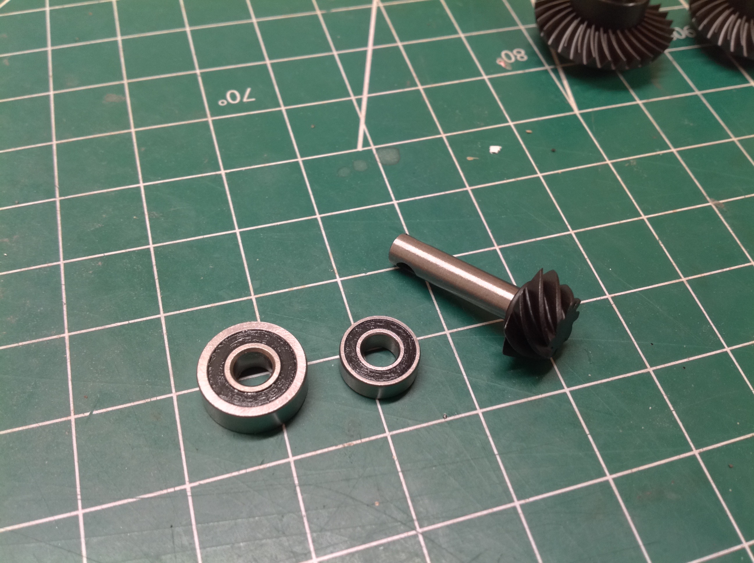
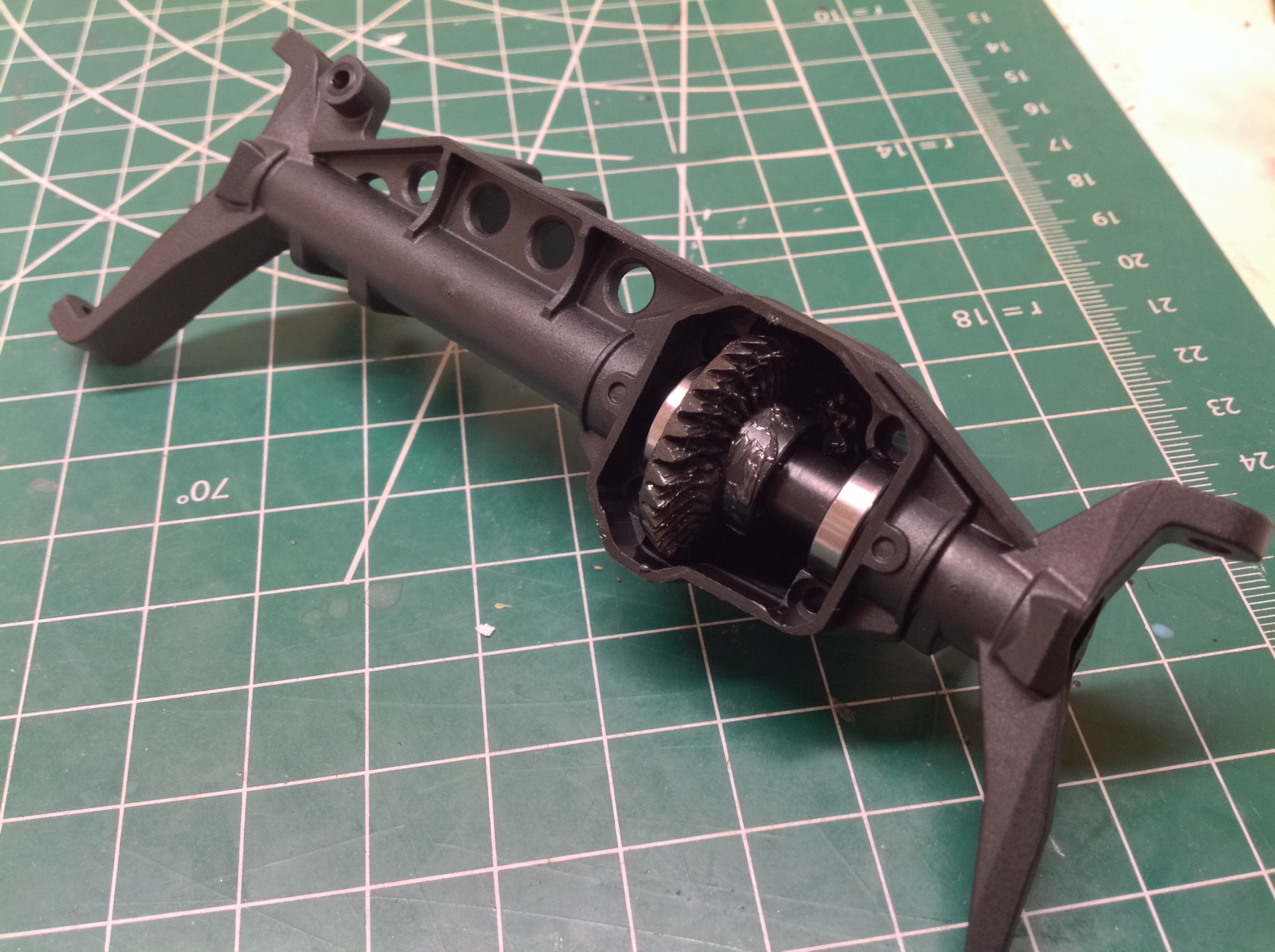
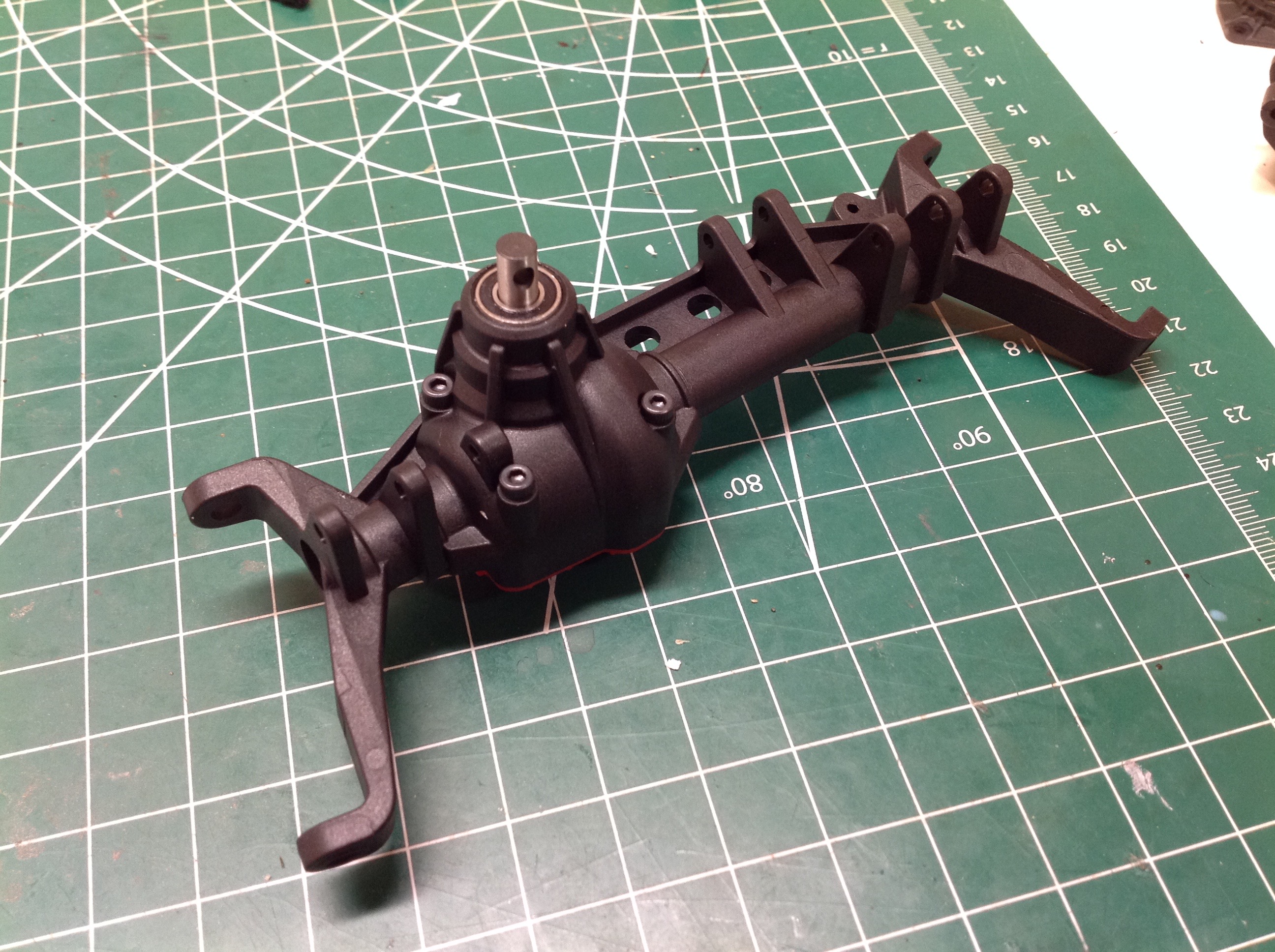
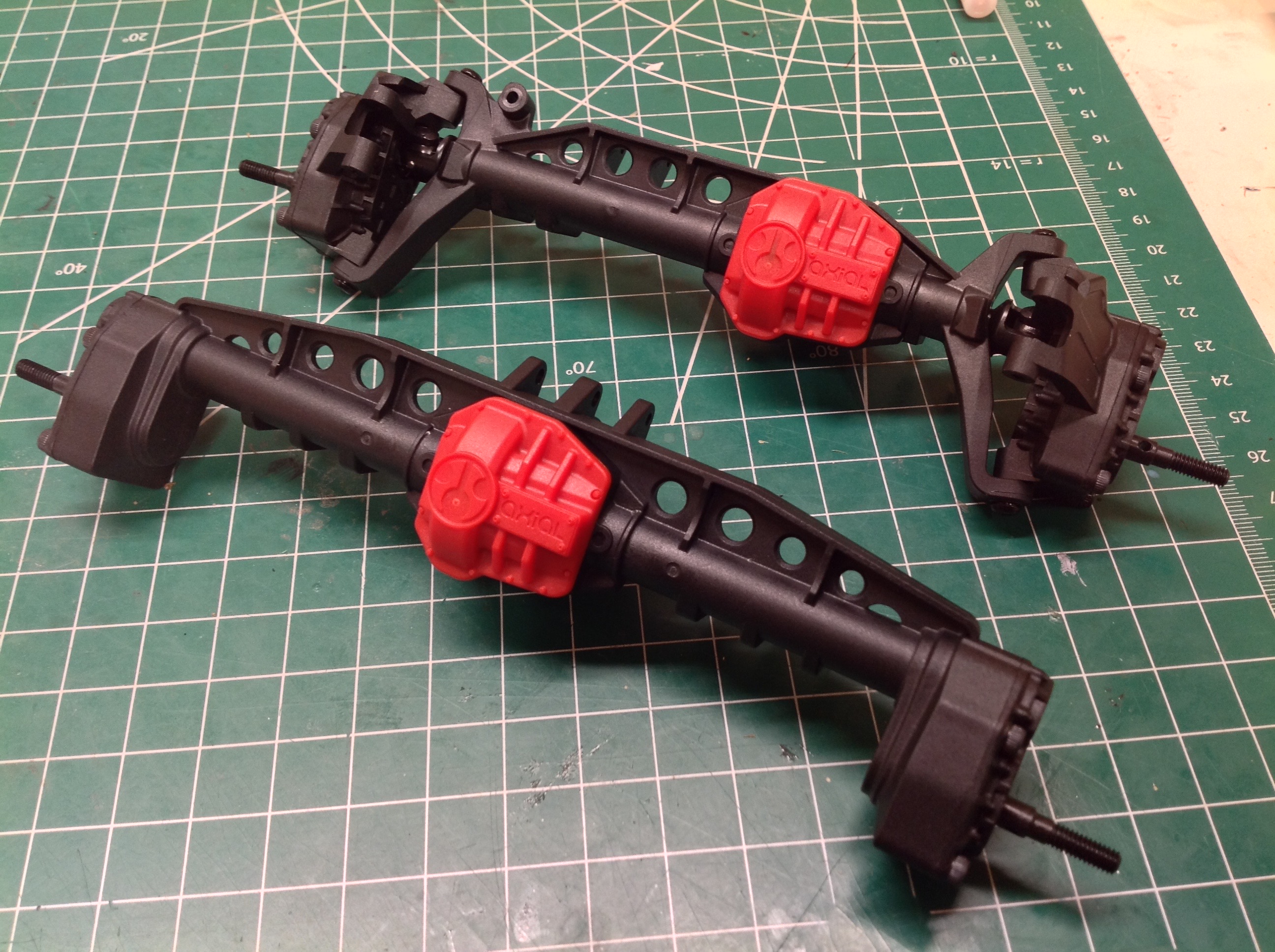
The plastic axle housings are fiber reinforced, and you also see the
huge stiffening beam running across the top. The greased diff
locker drops into the offset pumpkin and diff cover contains the pillow
blocks securing the bearings. You'll notice that the pinion gear
meets the axle above the center line which means that these are hypoid
gears for additional ground clearance and reduced drive shaft
angle. nice. You can also see the significant kingpin
inclination angle on the portal C-hubs.
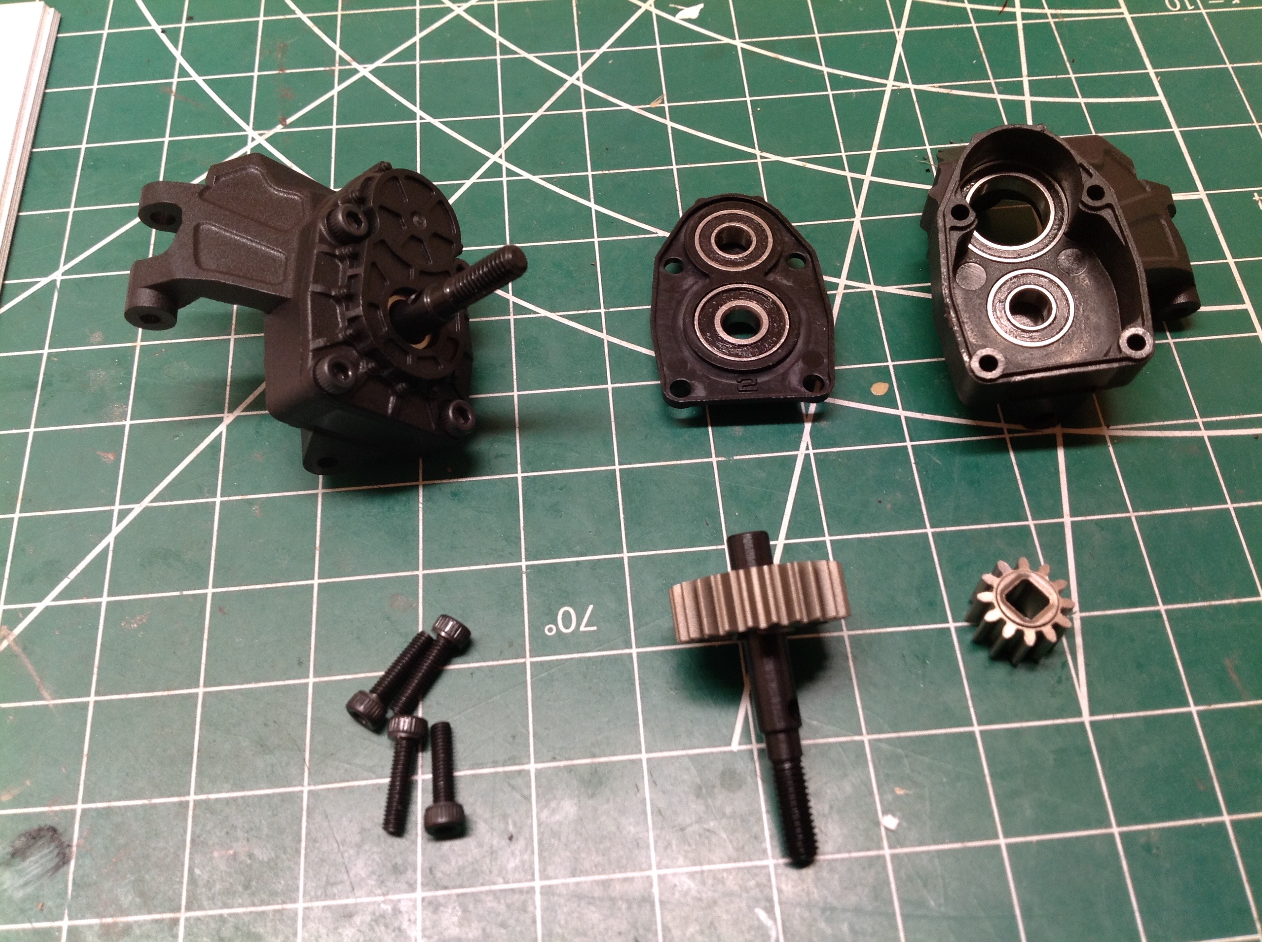
Next up are the front steered portal hubs. There is no idler gear
so that means these portals reverse the direction of rotation. The
picture on the left shows how they are assembled. The 32pitch
steel gears and 23T and 12T so the reduction is 1.92:1. I'm not a
big fan of the square drive corners on the small gear because they
introduce big stress concentrations, but at least the corners are
aligned with gear teeth crests and not roots. The picture on the
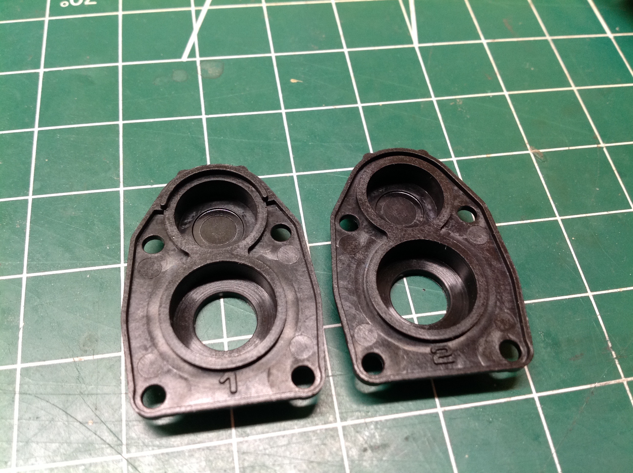
right shows that the portal hub covers are labelled "1" and "2".
The difference between them is very subtle which means they can easily
be installed wrong (1 is for the front) and they'll still kind of
fit. I have no idea why Axial didn't just make them common.
The difference seems to be the semi-circular flange sitting proud above
the upper bearing on the front covers. They should have been made
"Murphy Proof" by having different hole locations so they couldn't be
installed wrong.
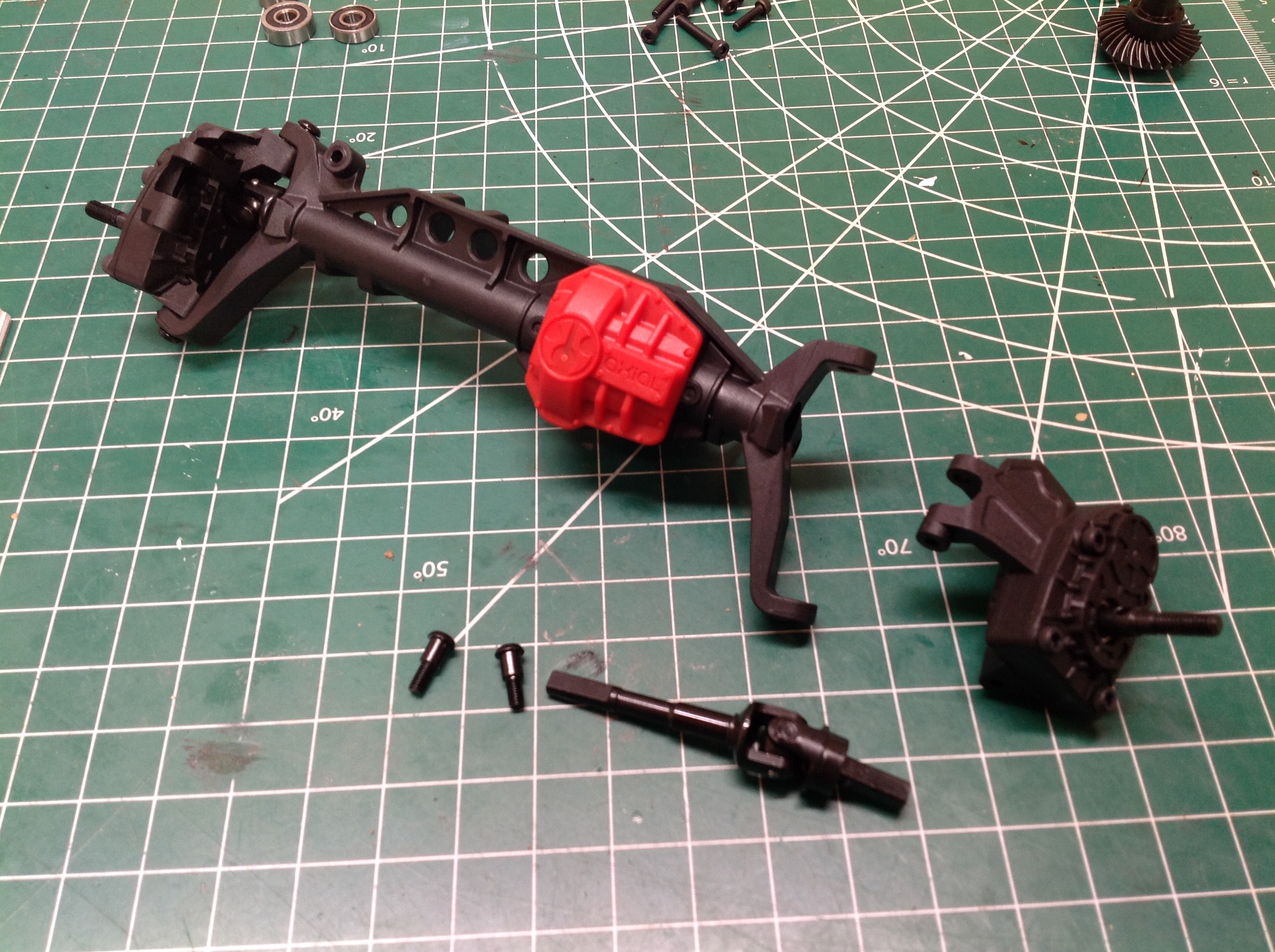
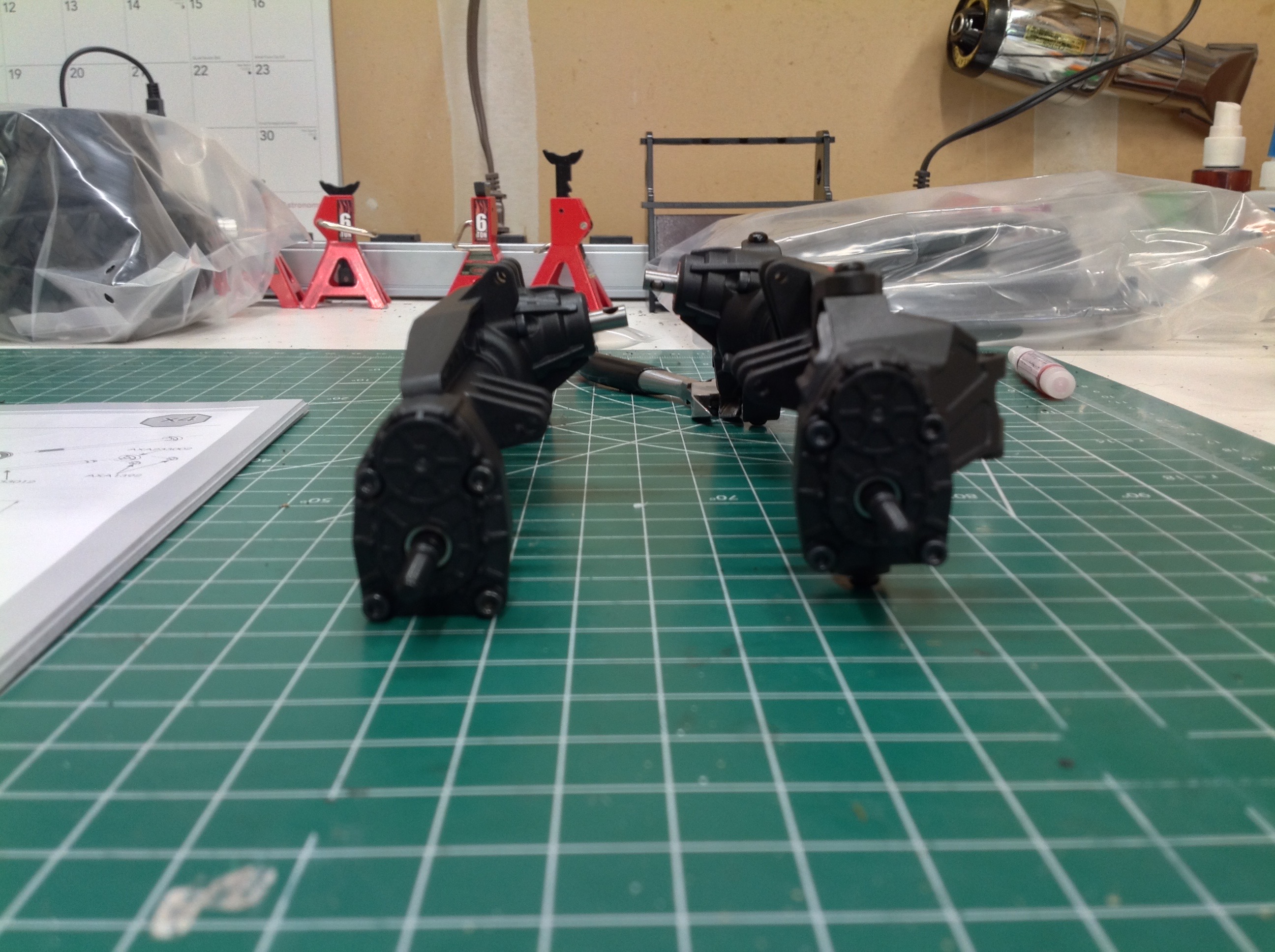
The front steel axle shafts have pre-assembled universal joints.
Since the pumpkin is offset, the left and right axles are very different
lengths. The rear axles are just straight shafts as shown on the
right. The rear axle uses all the same gears as the front.
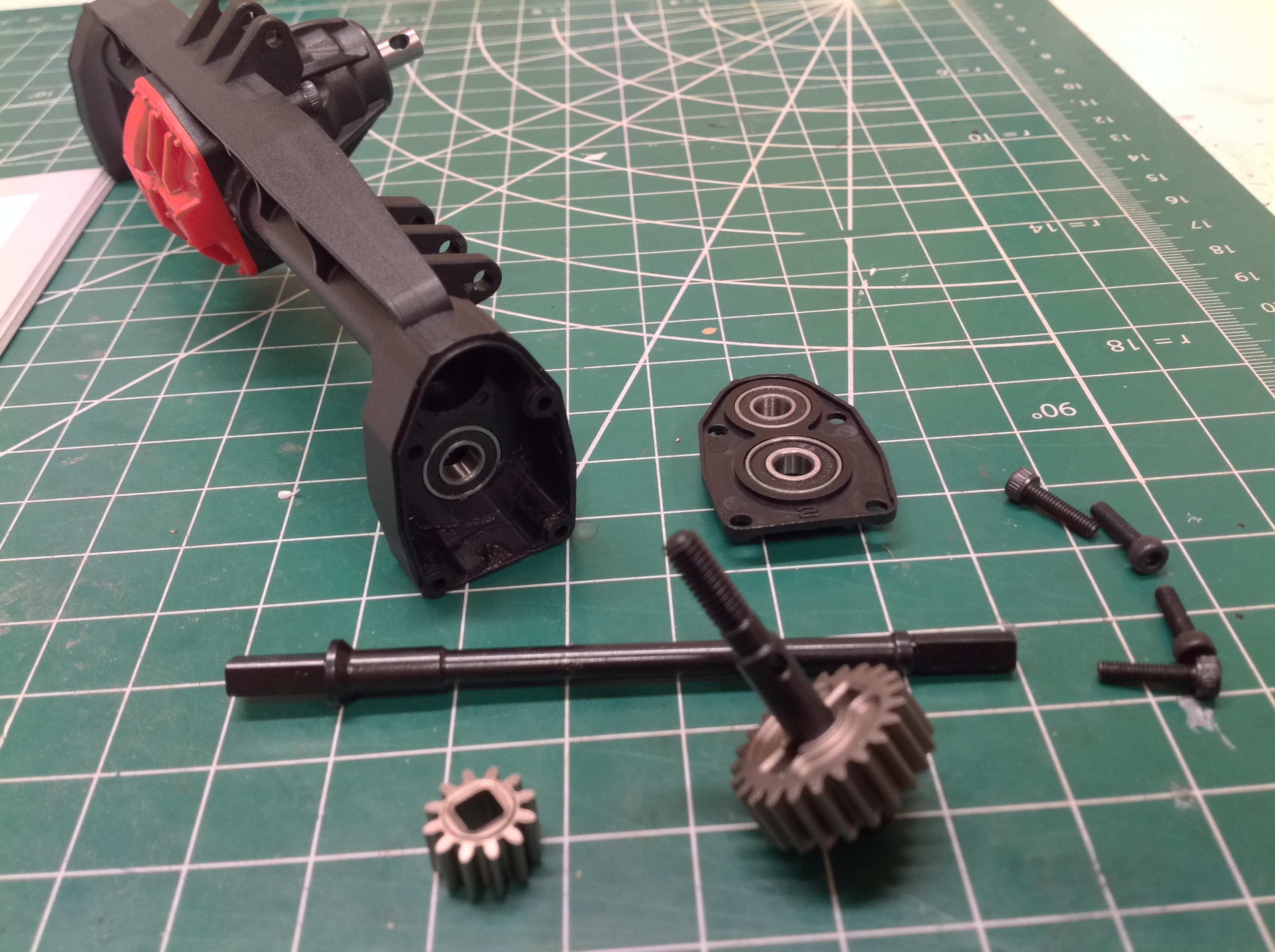
Looking closely at the picture on the left you can see that the pinion
gear of the rear axle comes out at a large upward angle but the front pinion
doesn't. This is opposite of what I would have expected and means
that there is no (or very little) caster angle on the steering. The completed axles
are shown on the right.
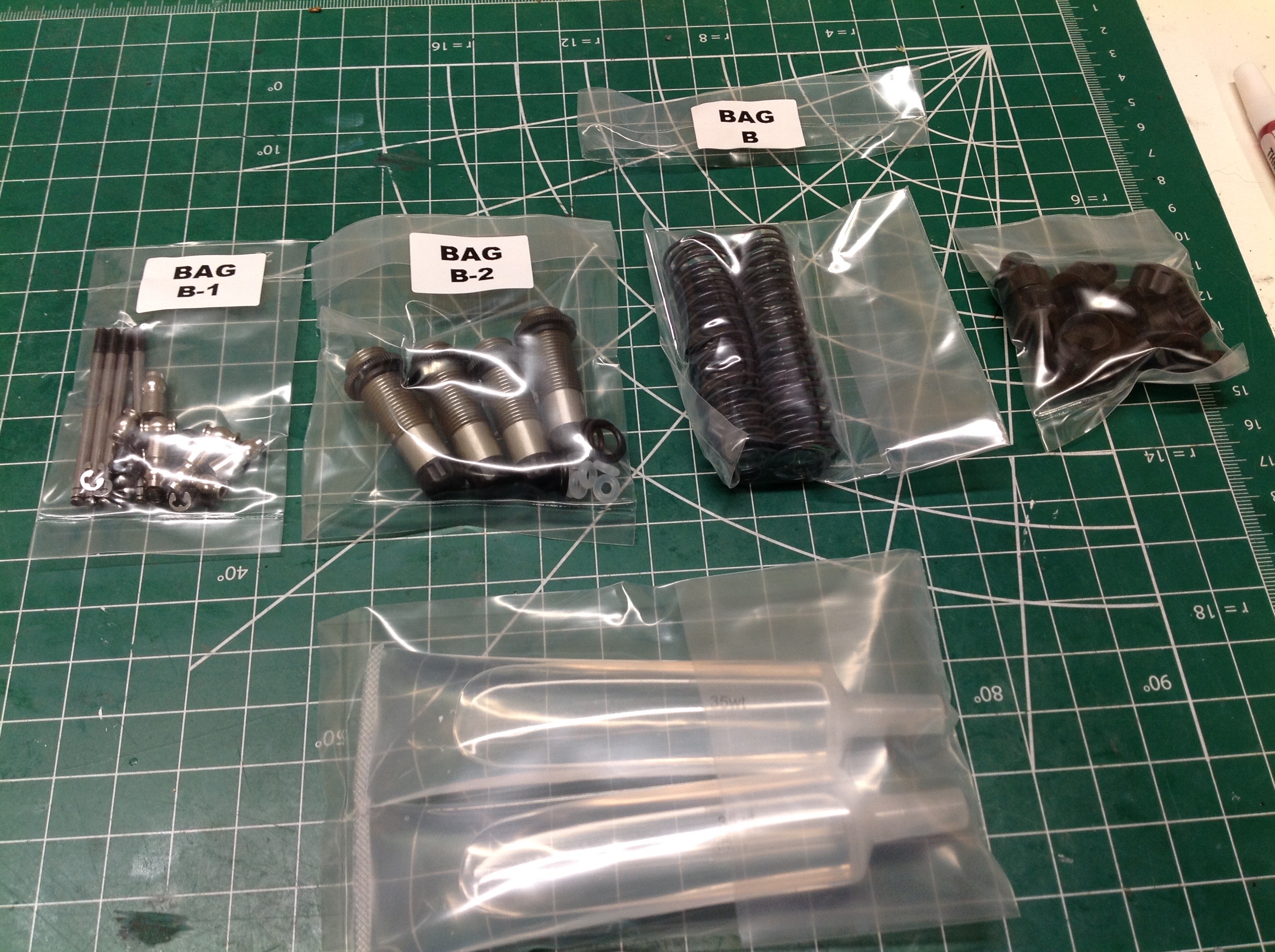
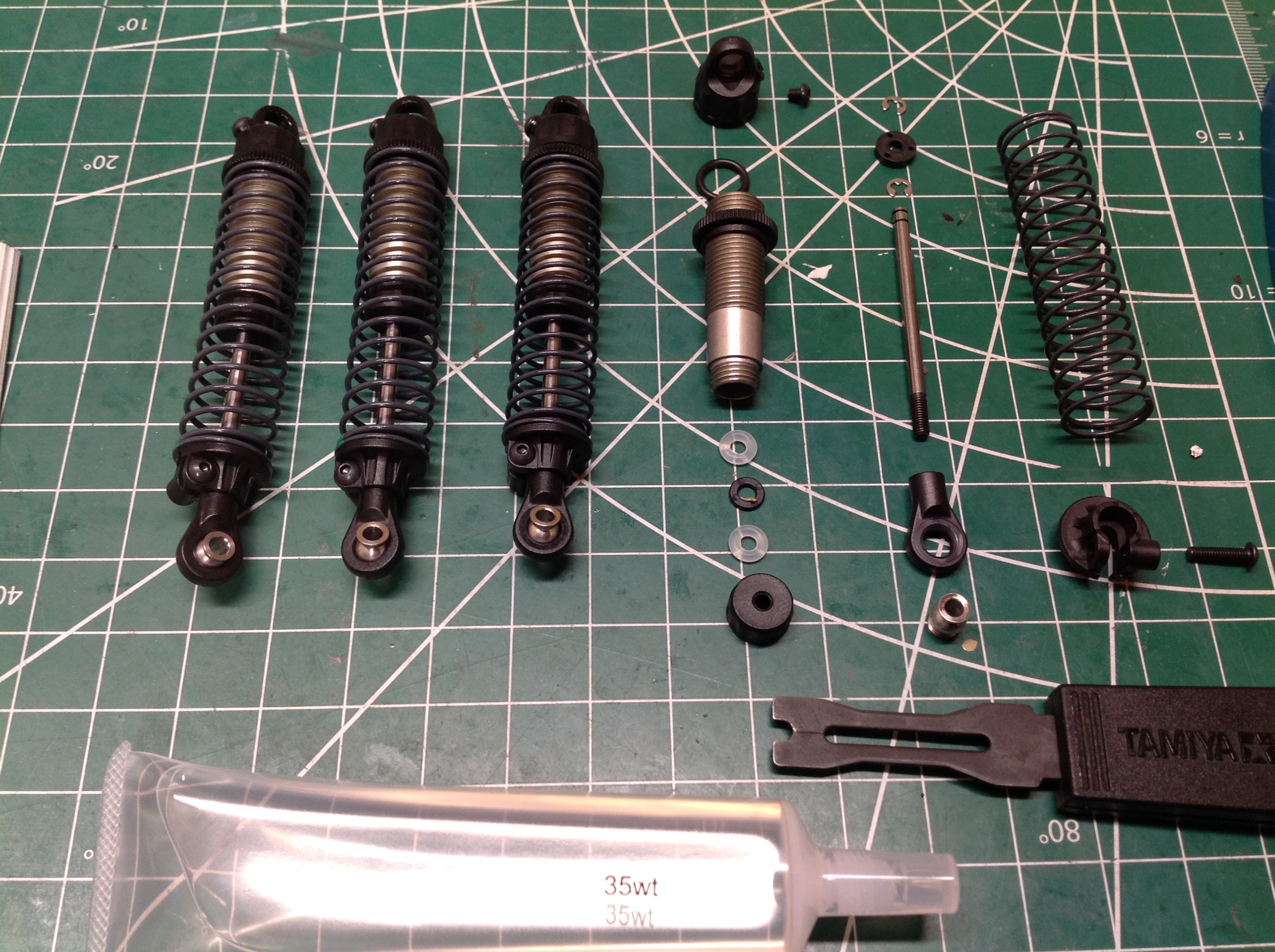
The B bags contain all the parts to make the shocks. The shock
bodies are machined aluminum with plastic caps and rod ends. An
exploded view is shown on the right. The kit comes with 35 weight
oil for all 4 shocks which are all built the same by default. The
pistons have 3 holes each. The pivot balls are steel. There
is no volume compensation in these shocks so the bleed screw in the cap
must be used to reduce the volume of oil until they don't hydraulically
lock. One nice feature of these shocks is that the spring perch
locks to the rod end to keep it from falling off and getting lost in a
rollover.
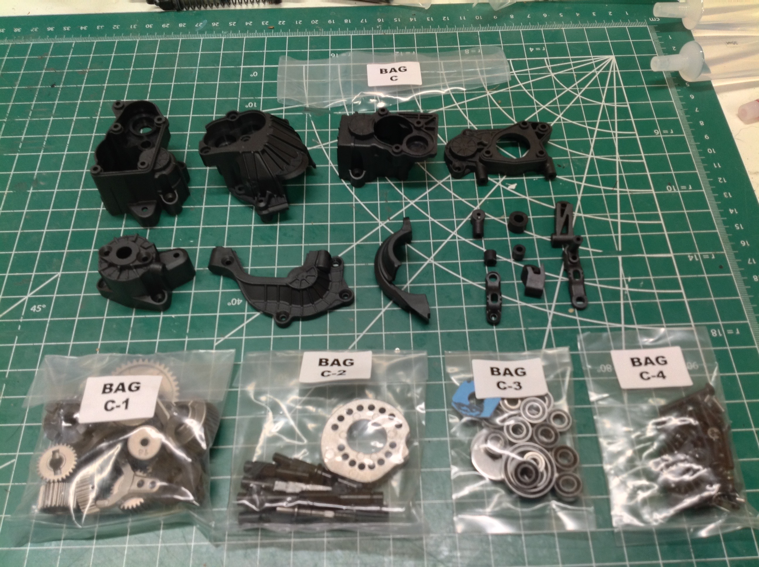
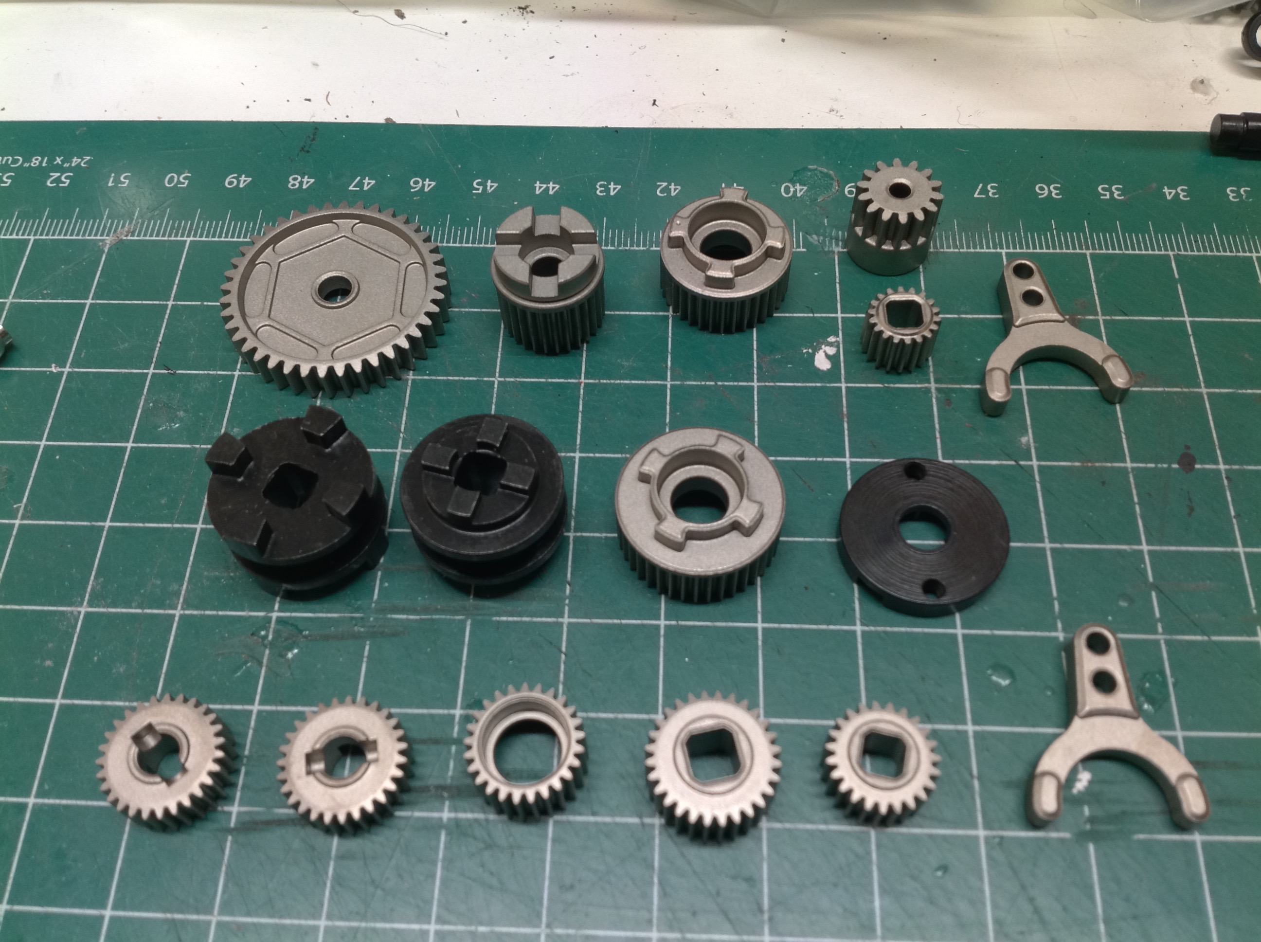
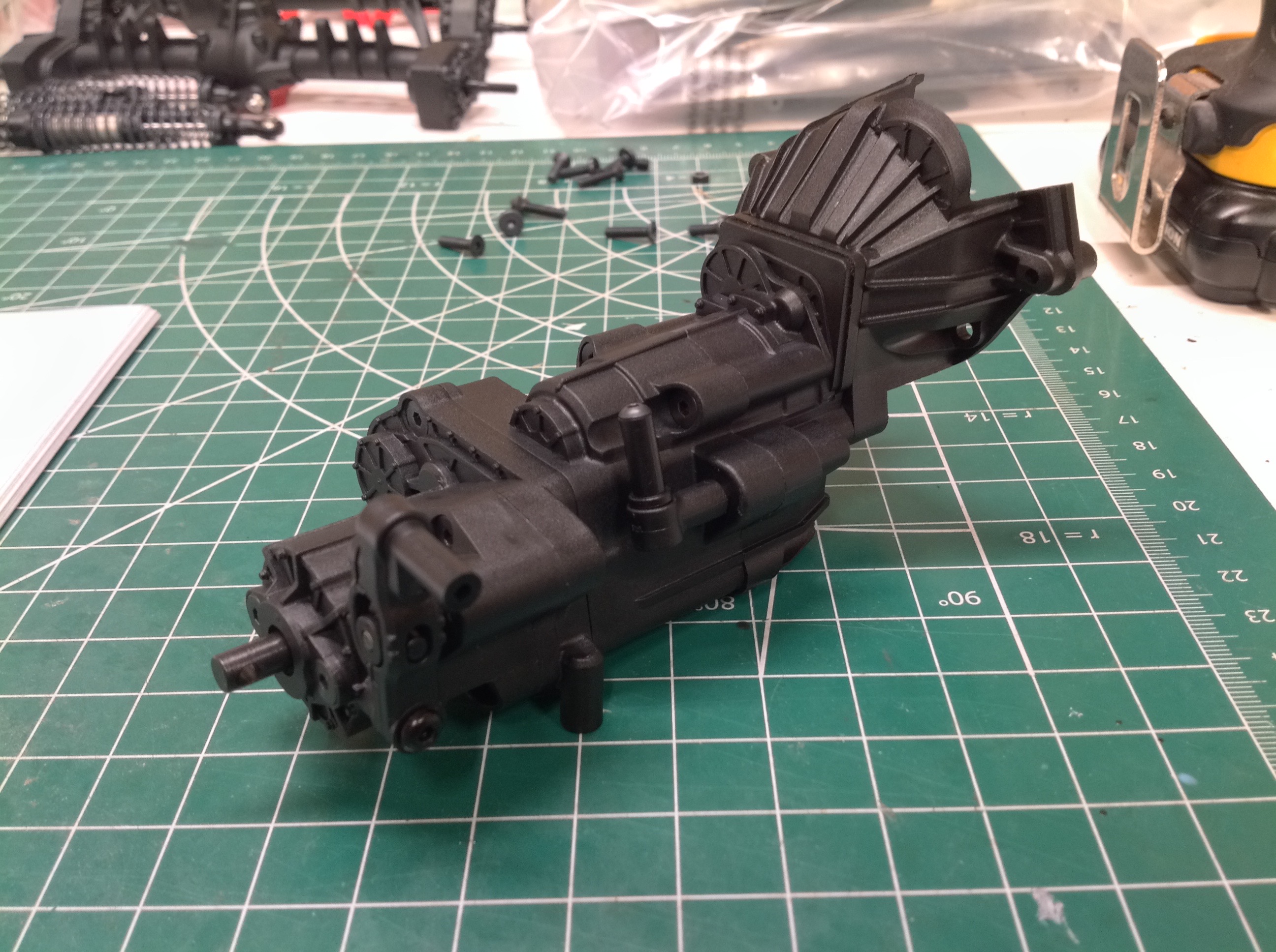
The C bags contain the parts to built the glorious transmission.
The right hand image shows the huge number of metal parts. All of
the gears are metal as well as the driving rings, shift forks, slipper,
and dog stops. Unlike the differential gears, these appear to be
sintered rather than machined.
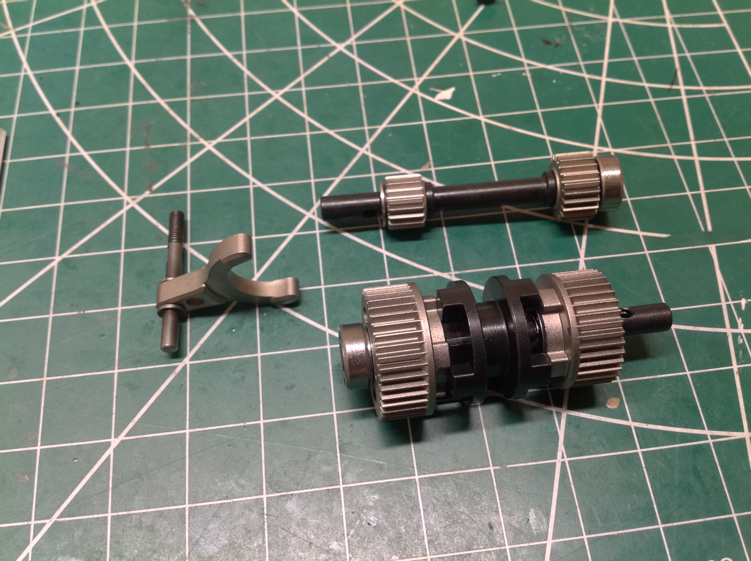
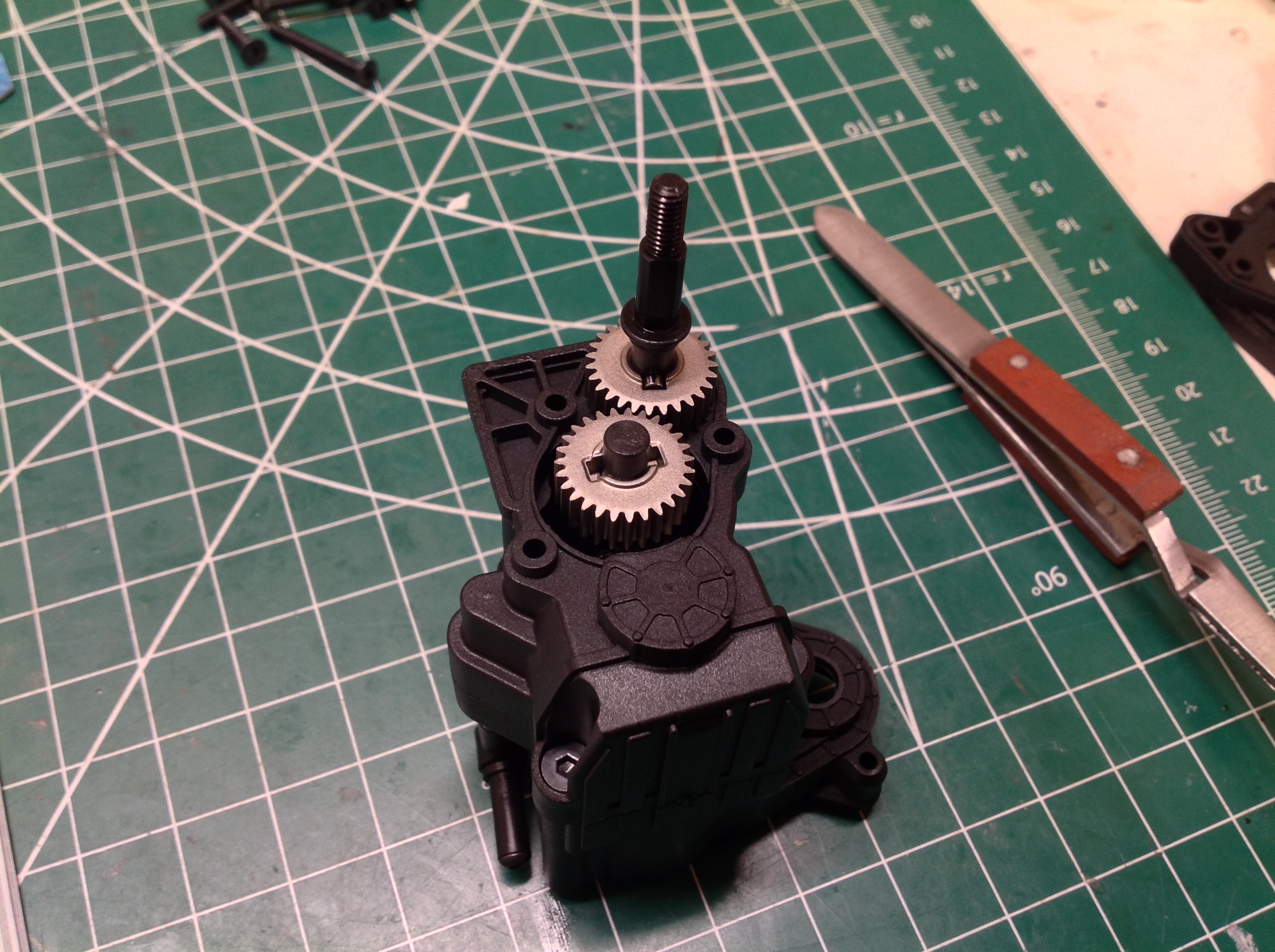
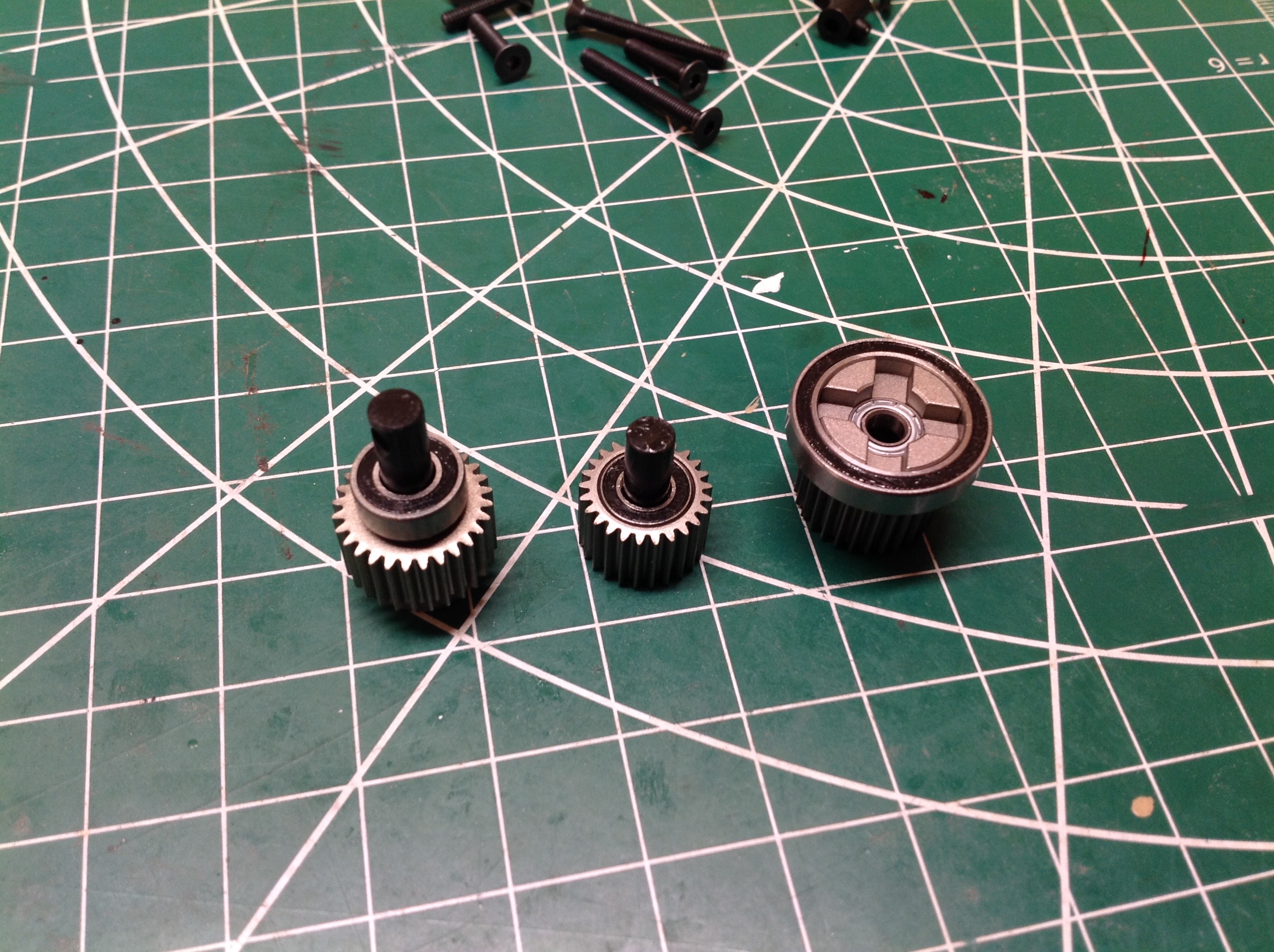
Here we see the input and output shafts for the two-speed
transmission. First gear is geared down 35:23 (1.52:1) while
second gear is 40:18 (2.22:1). In my opinion, this is too small a
difference between gears. You hardly notice the difference when
switching. I would have liked second gear to be taller. The
two smaller gears on the input shaft are locked to the shaft and driven
by the motor while the two larger gears on the output shaft ride freely
on bearings. The black driving ring between them is locked to the
shaft,so whichever is engaged drives the output shaft. The shift
fork translates the driving ring. There is technically a very
small neutral range between the gears, but it is not intended to be
used. The shift servo should be set as with a two position
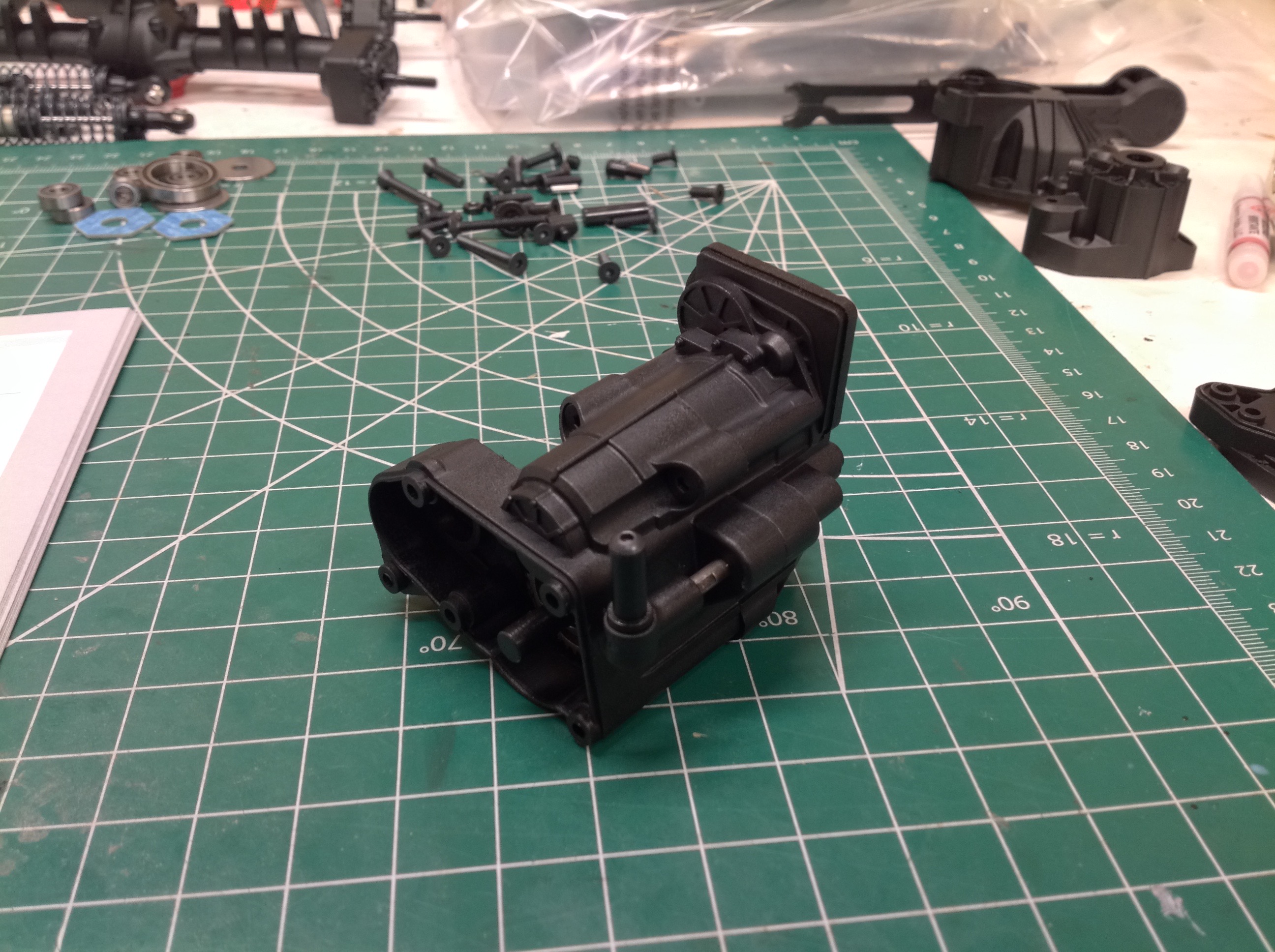
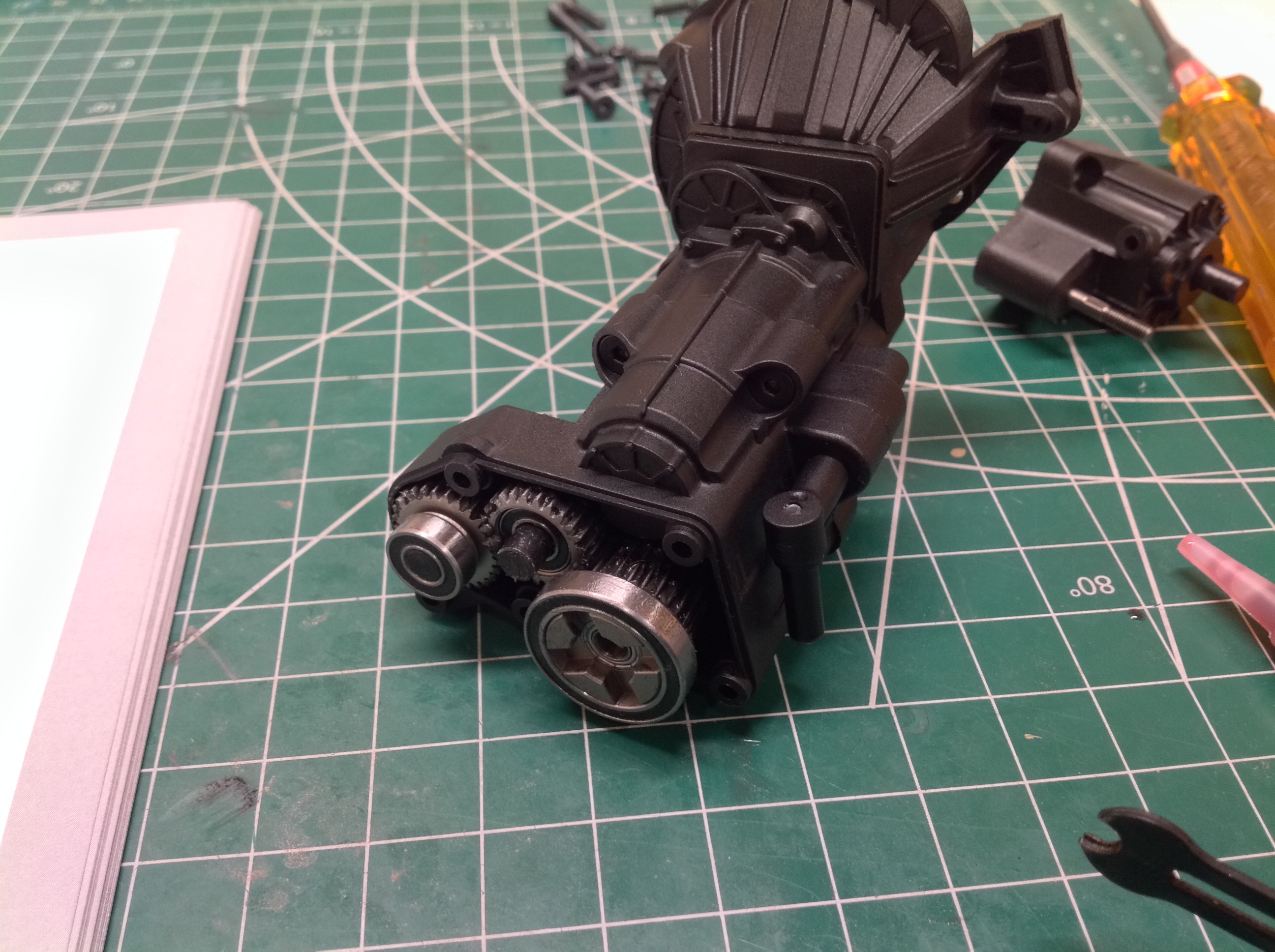
switch. The picture on the right shows these gears installed in
the housing which completely obscures them. The shaft protruding
from the lower right is the output shaft.
This set of gears sits on the input side between the motor and the
two-speed. These gears serve two purposes. Firstly, they
reverse the direction of rotation from the motor which is needed because
the portal hubs introduce another reversal later on. The second
purpose is less apparent. These gears are the same size so they
have a ratio of 1:1, however an alternate set of 1.7:1 can be installed
instead for further reduction. These are intended to be used if
you build the model with straight axles instead of portals since the
portal reduction will be lost. Alternately, if you wanted your
truck to crawl really slowly you could use them even with the portals. Note that these optional gears are not included with the kit.
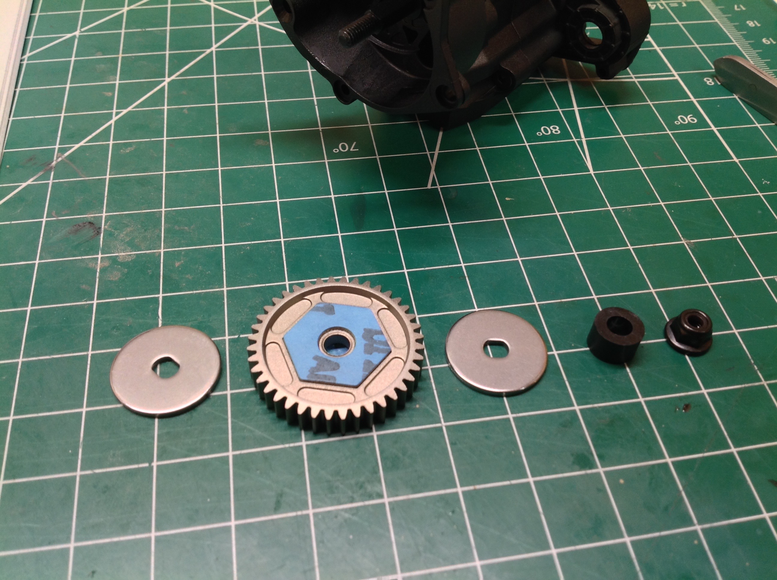
Now we build the slipper clutch which is built into the 40T metal spur
gear. There is a friction disk on either side of the spur which
lock to the shaft. The motor drives the gear, but the gear is only
coupled to the shaft through friction. The amount of torque
required for slippage is adjusted via the nut on the end. But now
comes a big "however". However, there is no spring in this
slipper. Instead there is a solid spacer. This essentially
means that once you tighten the nut down the slipper is locked which
makes the whole thing pointless (and not adjustable). Why?
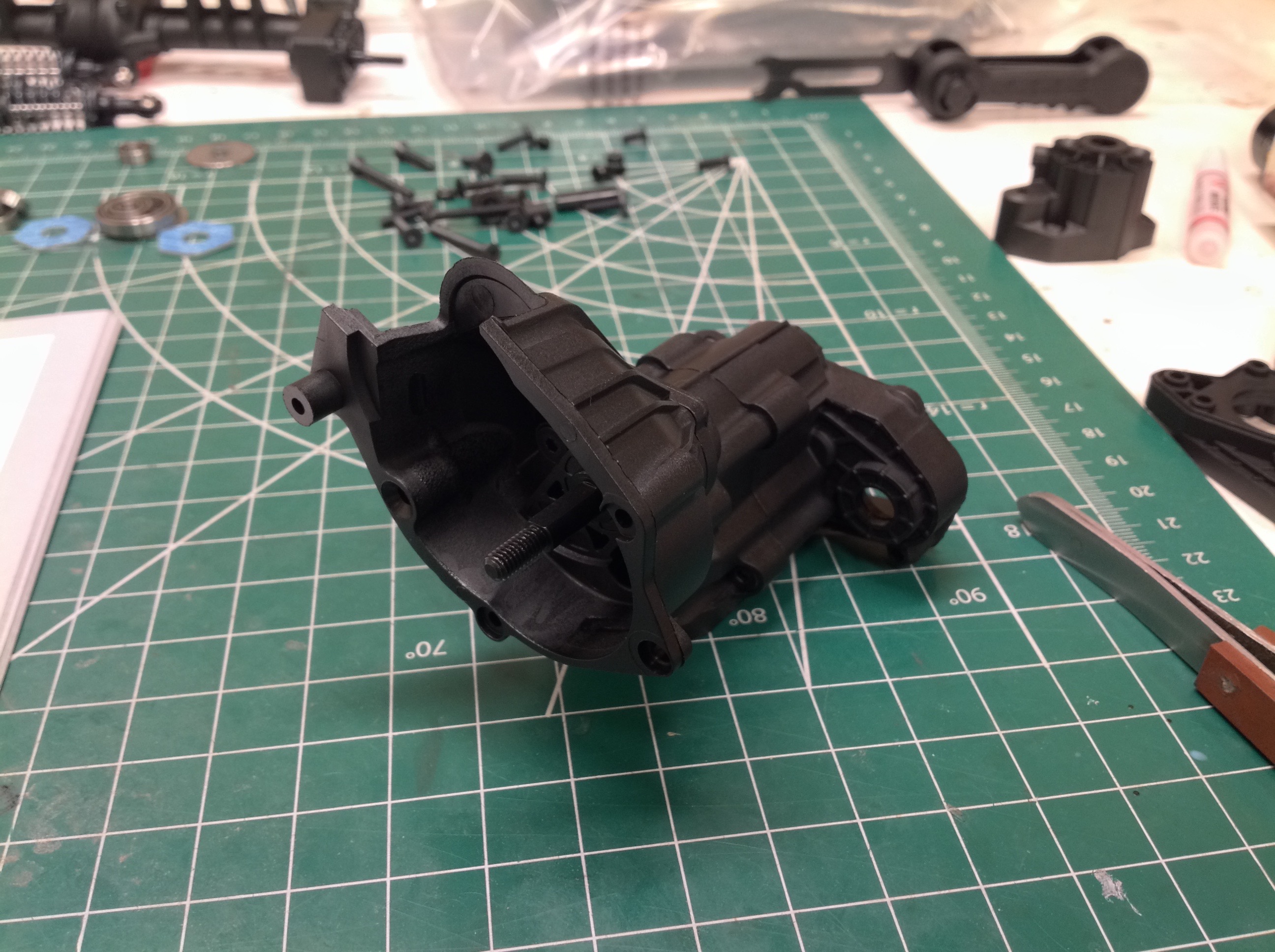
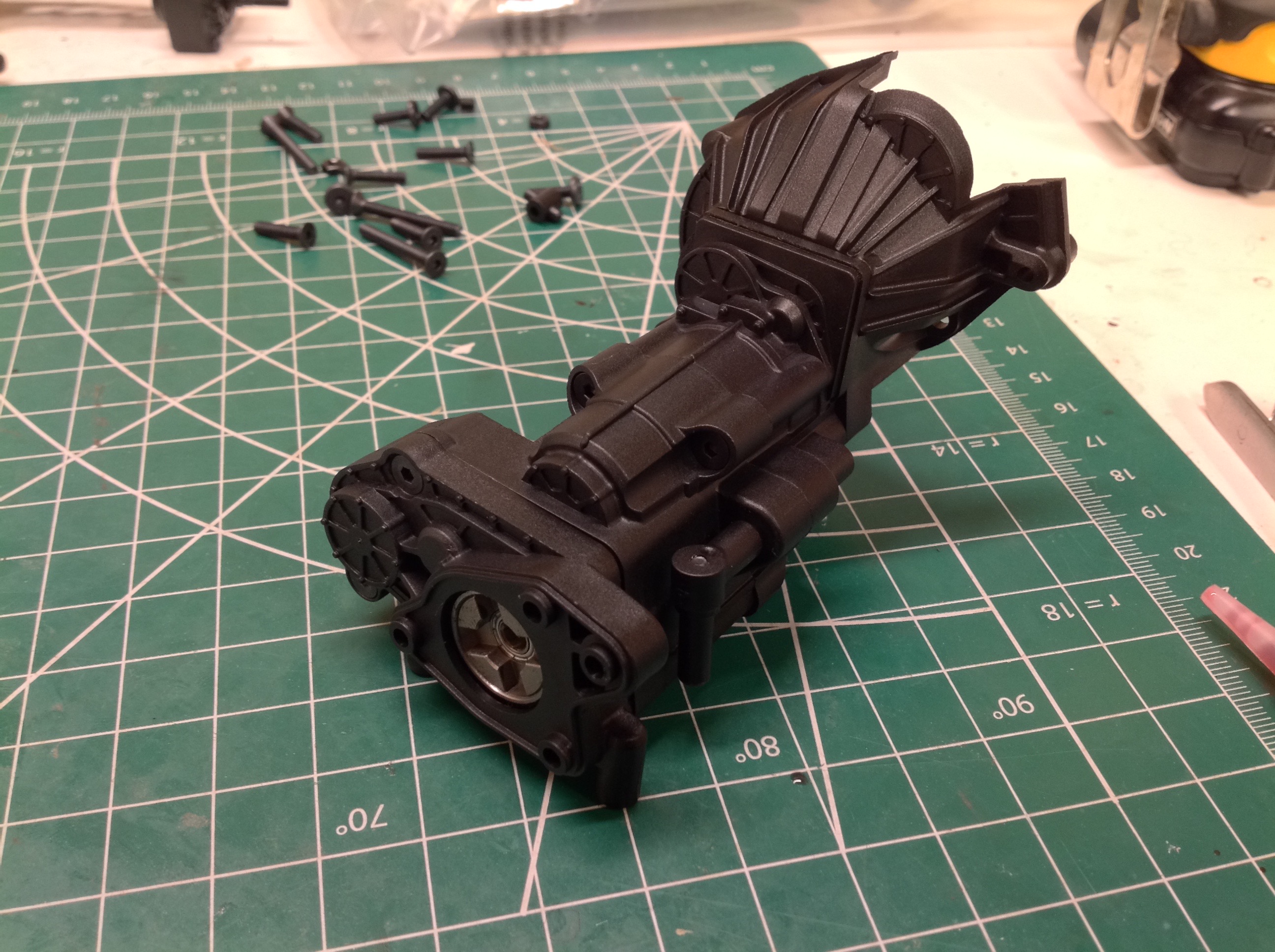
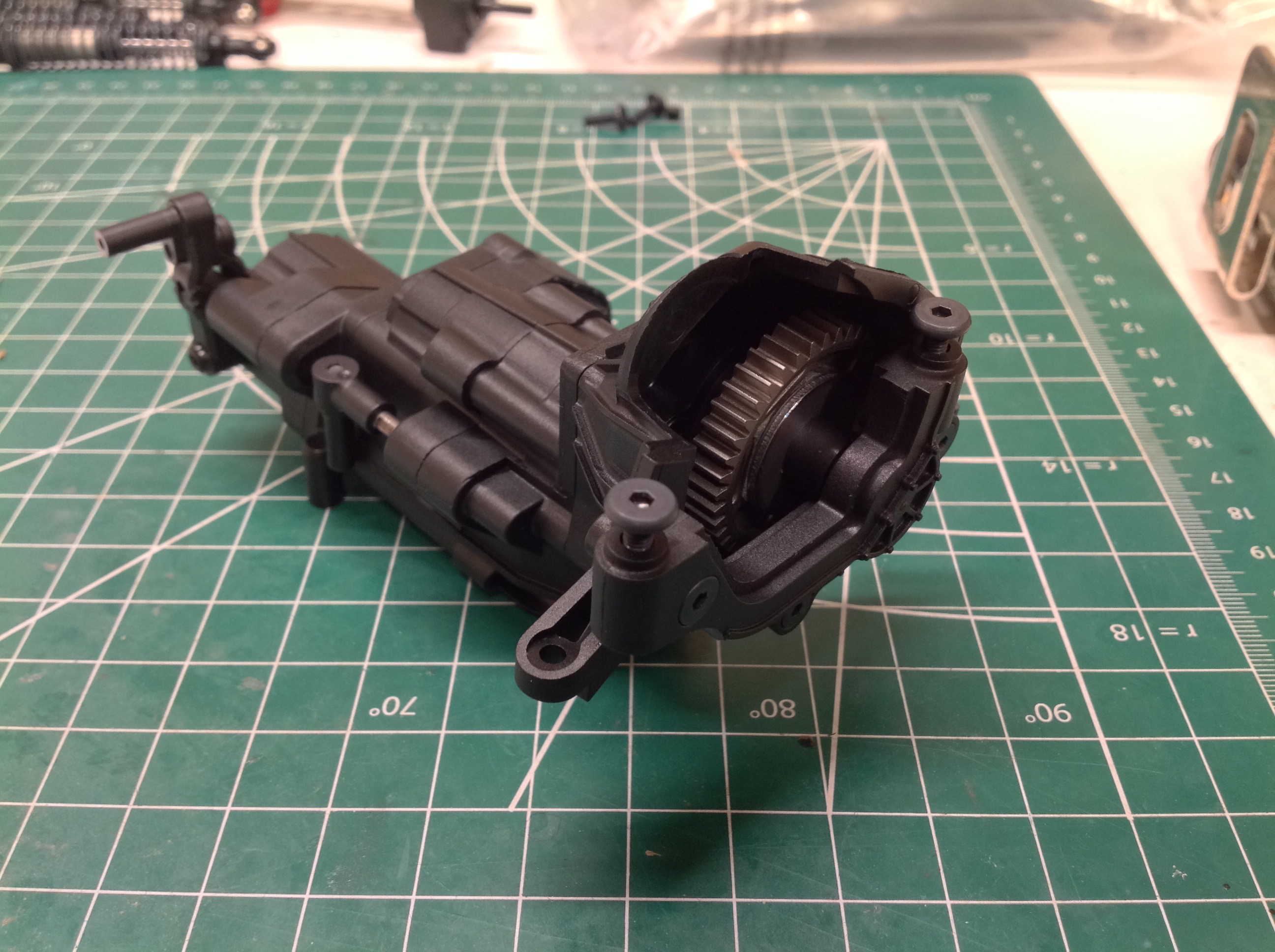
The dig function is built into the transfer case. The gear on the
right is connected to the transmission output and drives directly
through to the rear drive shaft. The gear on the left connects to
the front driveshaft and rotates the same direction because there is an
idler gear between. The front and rear rotate at the same speeds,
but overdrive is possible by changing the left and center gears.
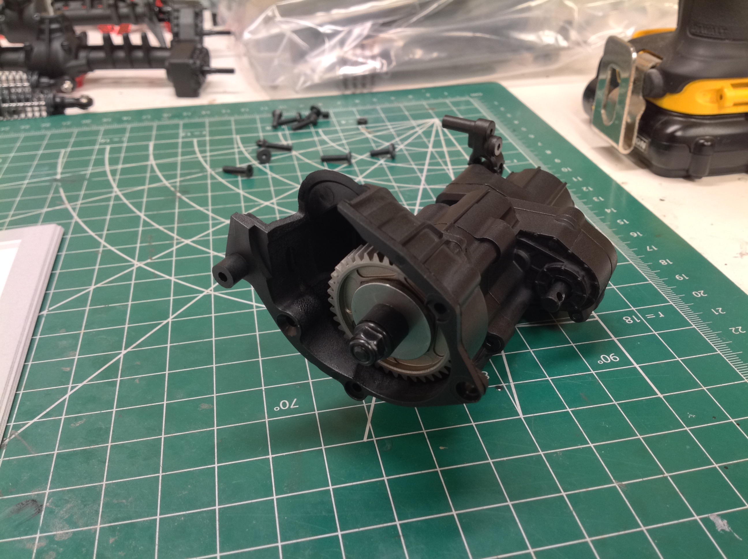
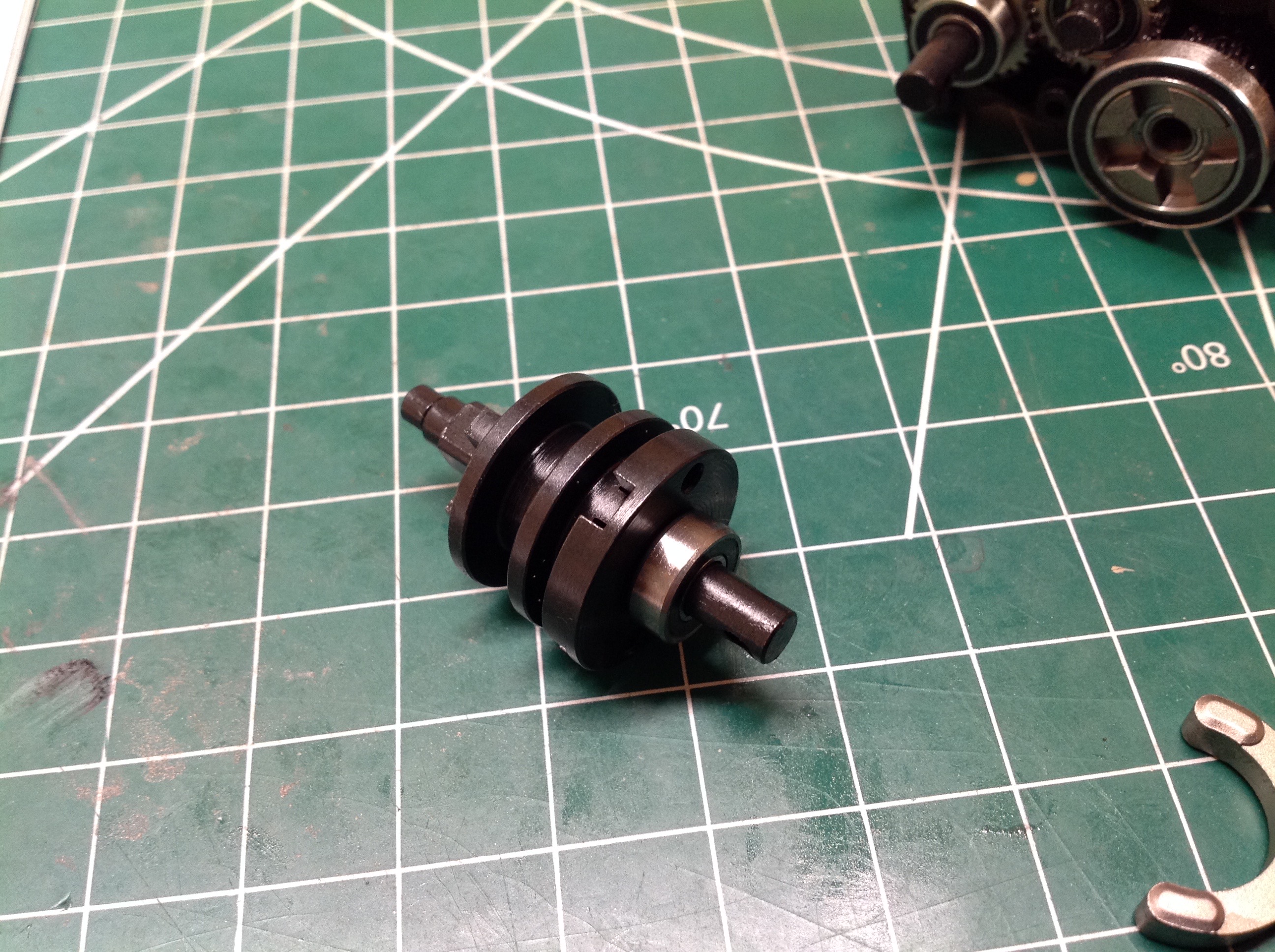
Now we'll build the dig. The driving ring shown on the right can
either slide into the transfer case to mate with the driving dogs on the
output resulting is a direct pass-through, or it can be translated back
to ground to the housing. This locks the rear drive shaft but
allows the front to continue to be driven by the motor.
These photos show the shift levers used to control the
transmission. The lever further aft rotates and controls the dig
while the lever further forward translates to control the two-speed.
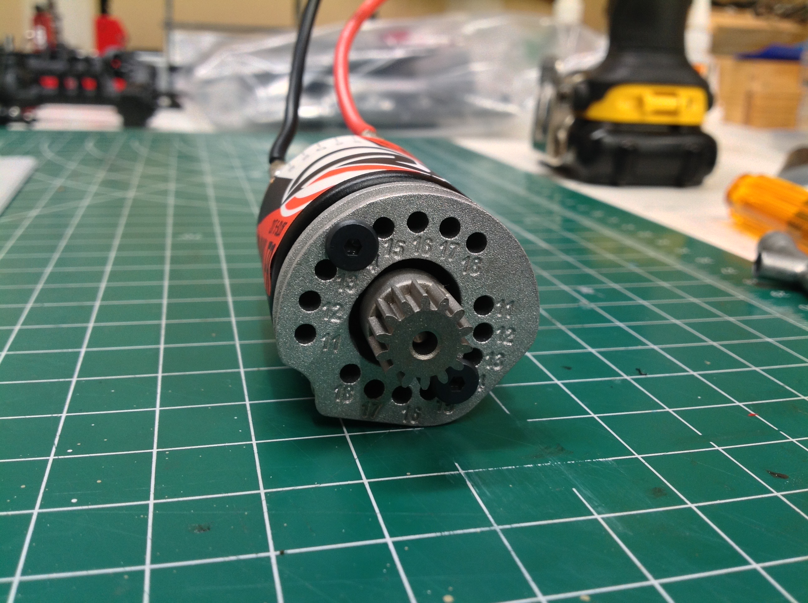
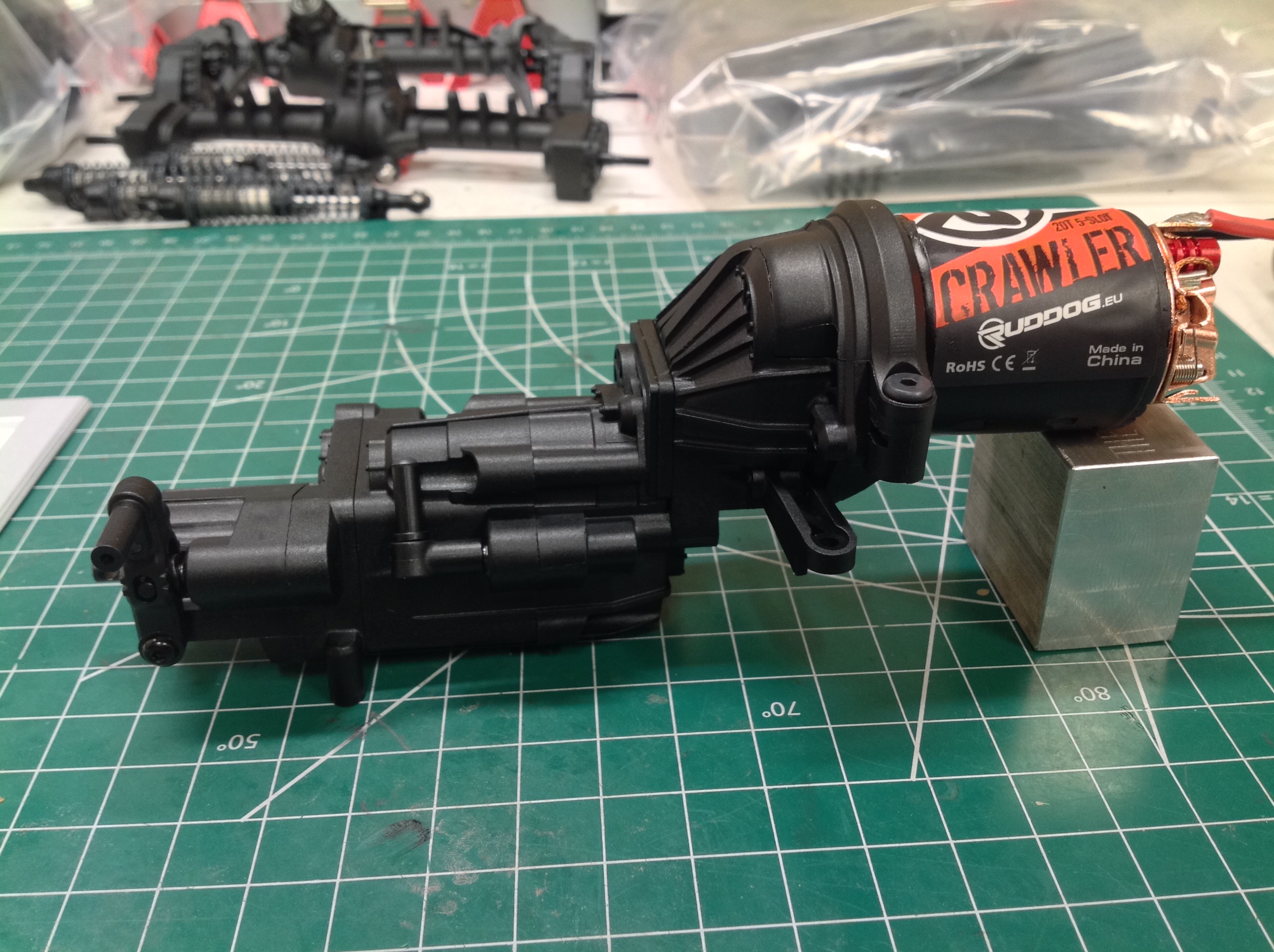
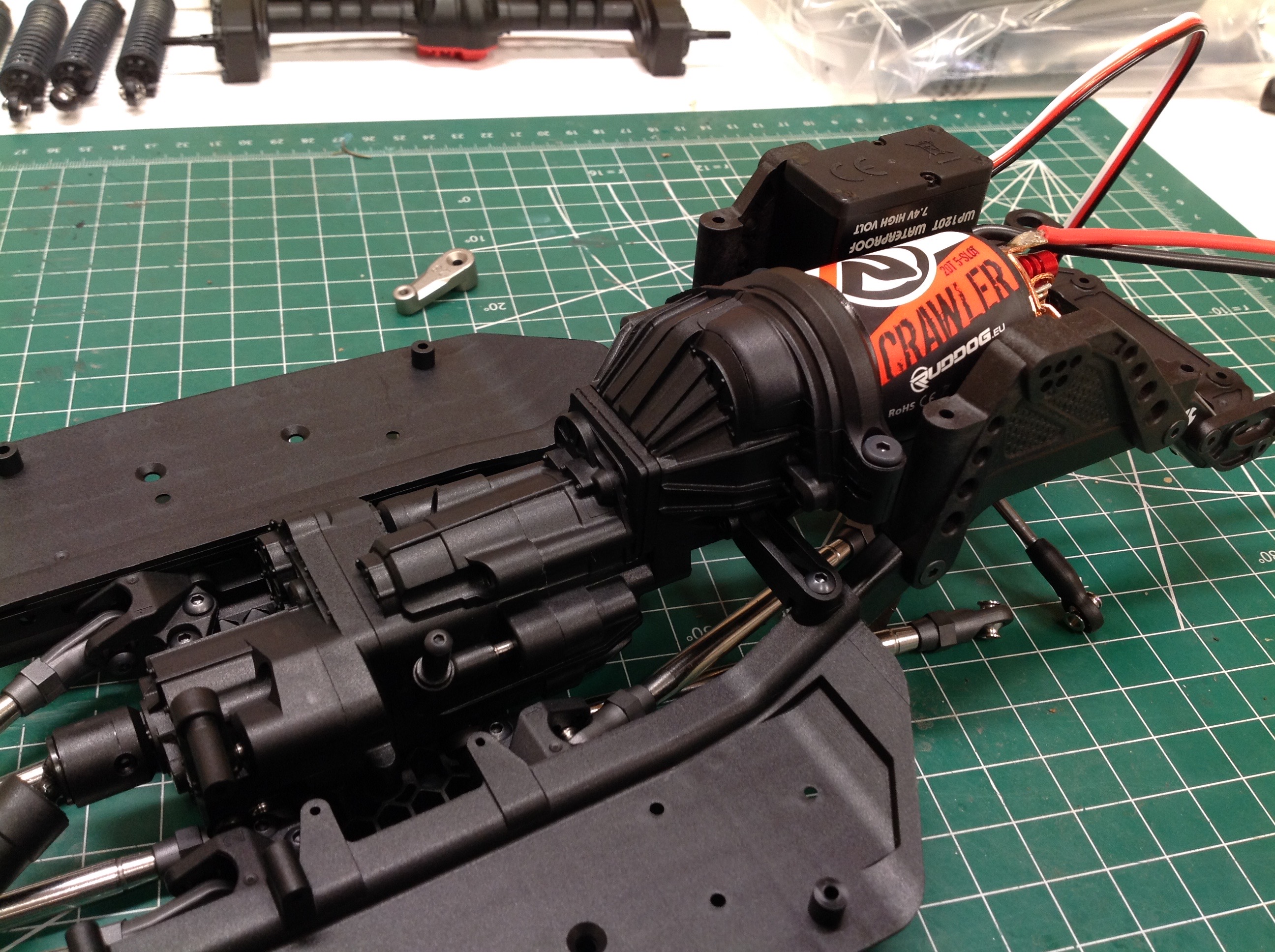
The aluminum motor plate is drilled to support pinion gears from 11 to
18 teeth using a determinant assembly so no gear mesh adjustment is
needed. The kit standard pinion is 14T. I ended up with a Ruddog 20T 5-slot brushed motor just
because that's what my local hobby store happened to have in
stock. The fully completed transmission is shown on the right.
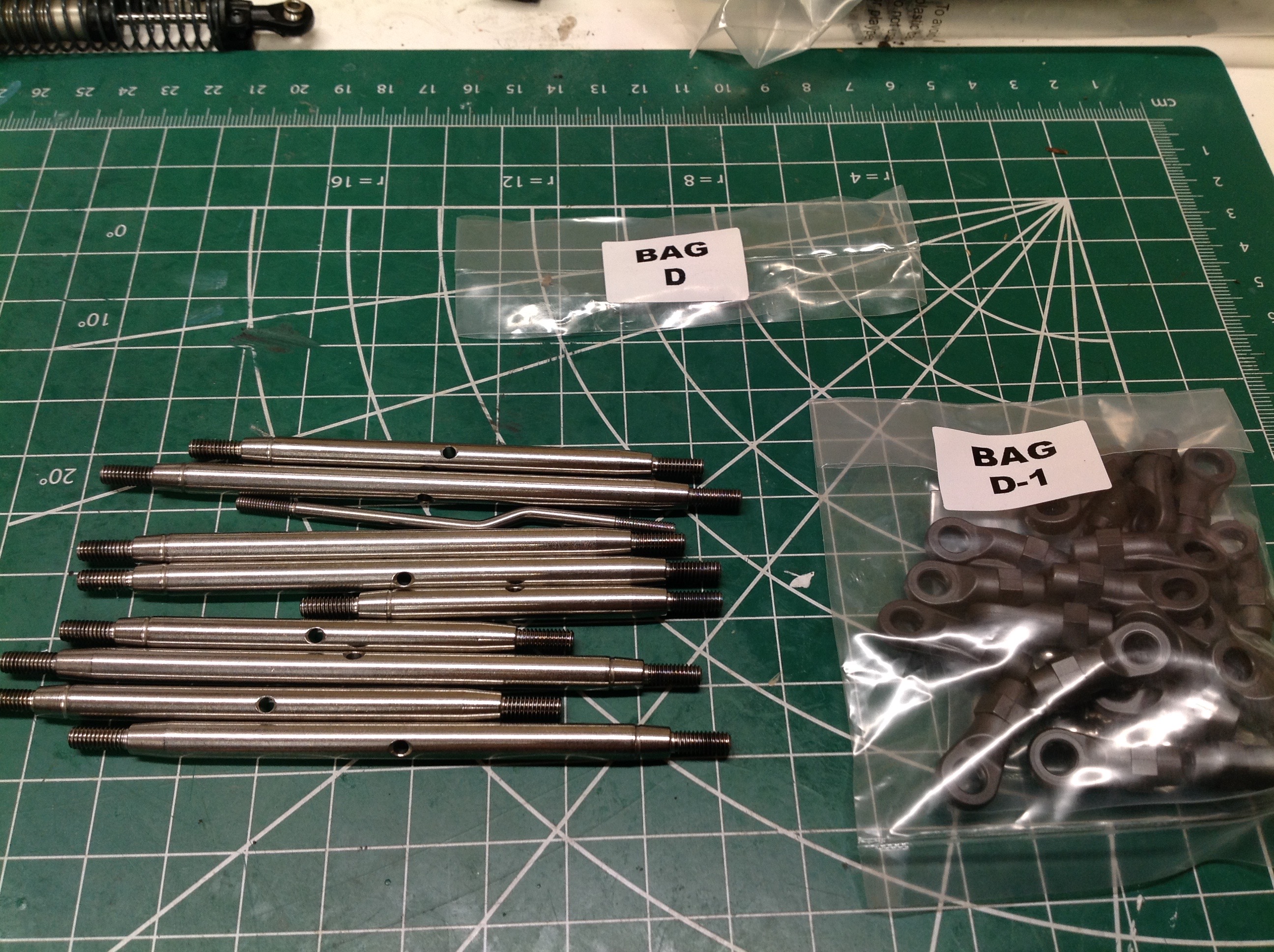
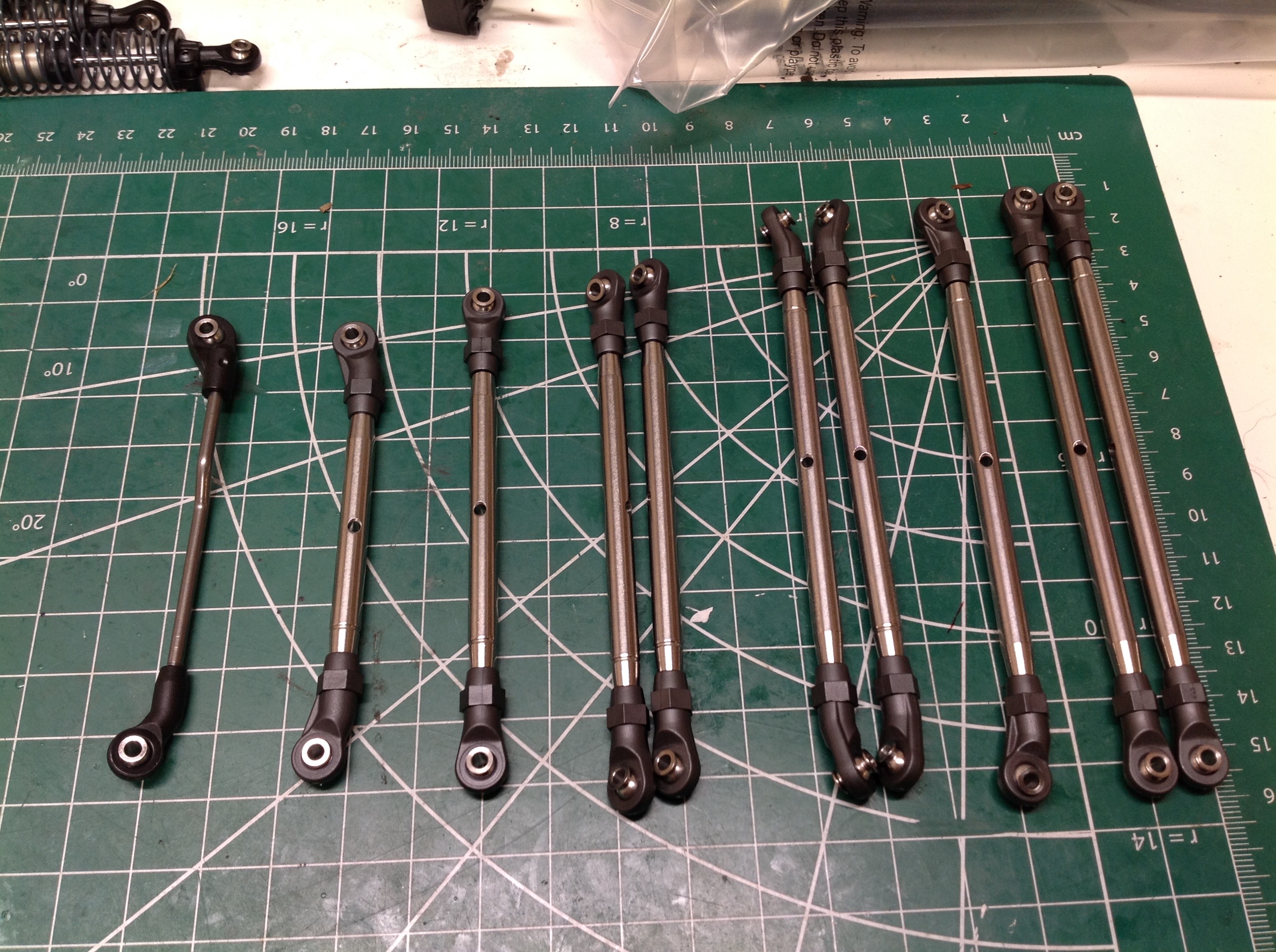
The ten metal links come in six lengths with five different types of rod
ends in the D bags. The rear suspension uses four links, and the
front uses three with a panhard bar. The remaining two are for
steering. Each link has a central hole you can pass a tool through
to help with installing the rod ends.
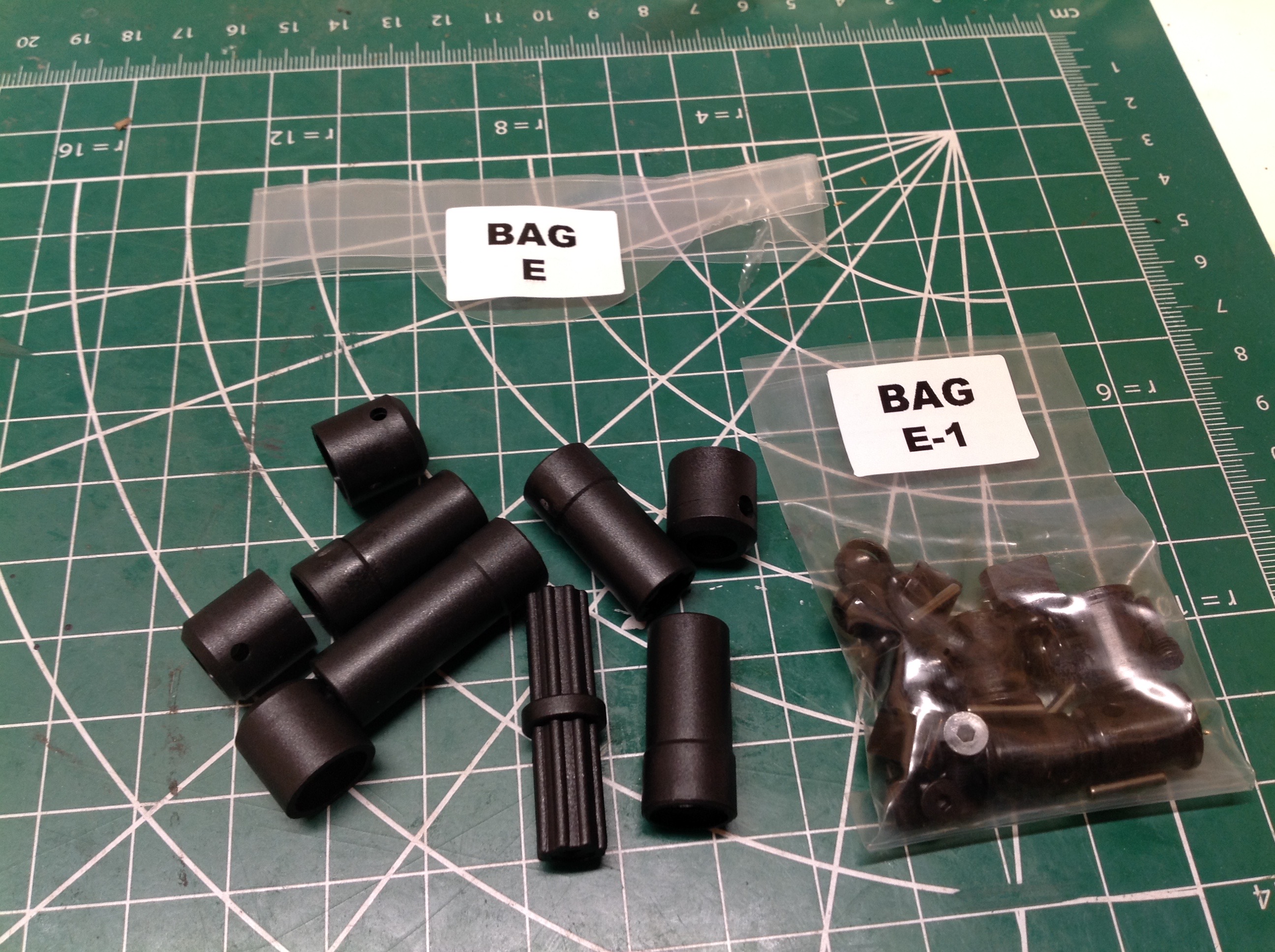
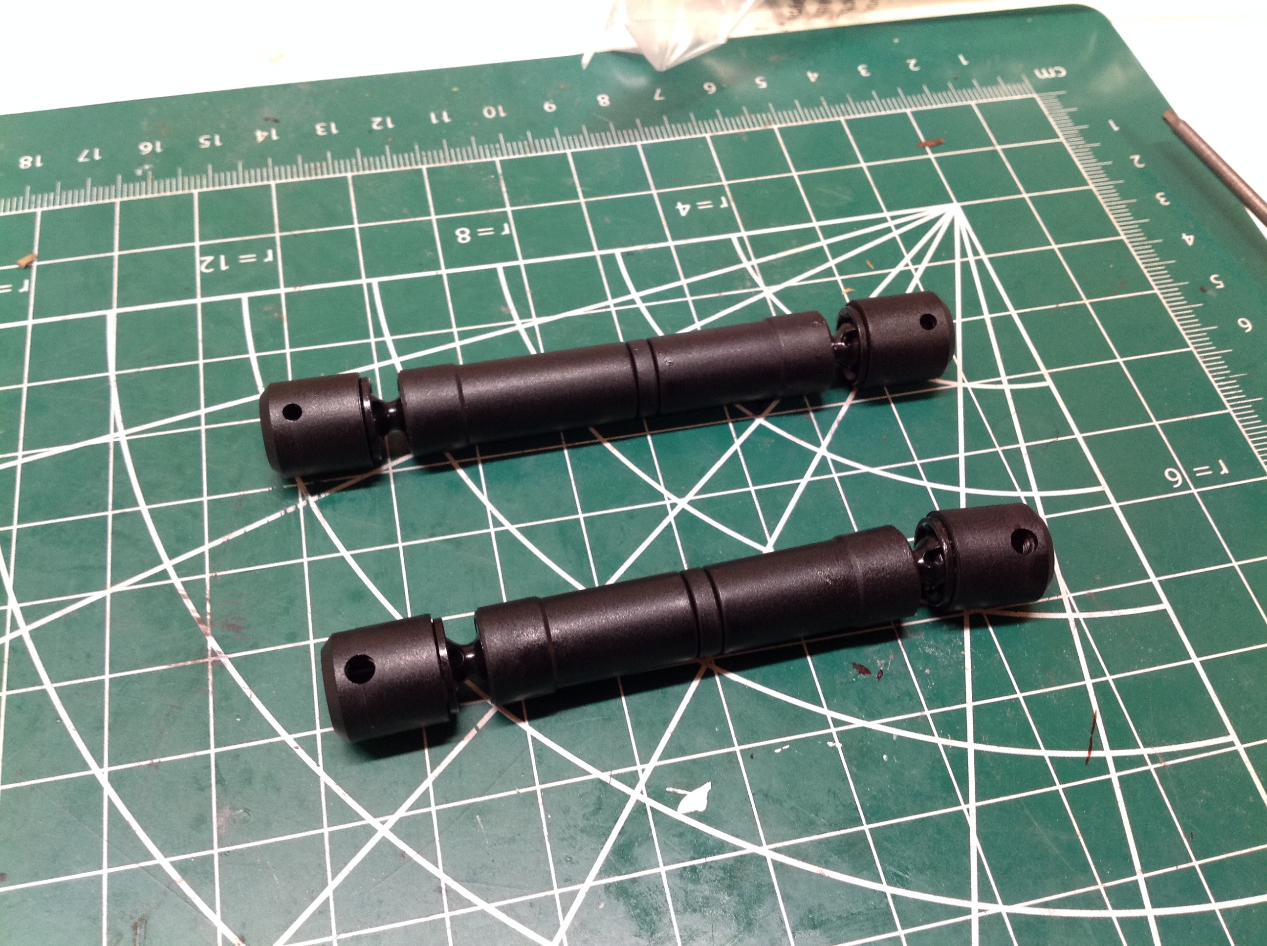
This image shows the contents of the E bags which build the drive
shafts. The drive shafts come in parts and must be built up.
Each has a CVD style end and a sliding spline in the center.
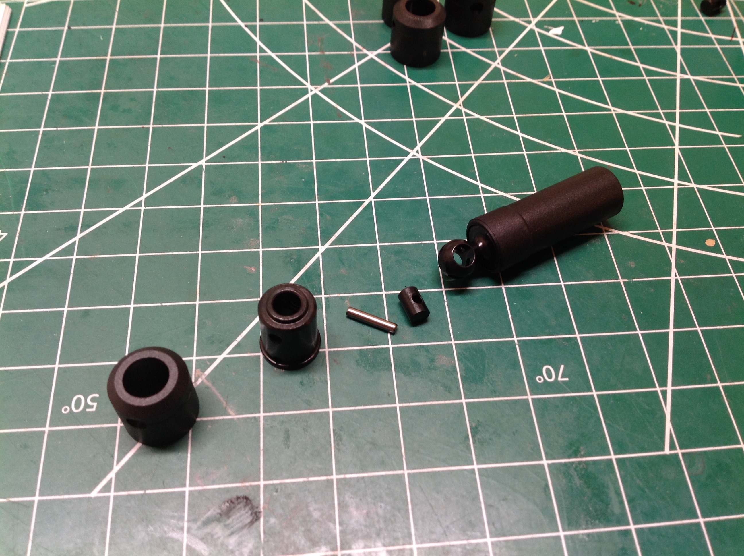
This exploded view shows how a CVD joint goes together. The cross
pin is inserted into the spherical socket, the mating cup is installed
over the top, and then a drive pin goes through the whole
assembly. The final plastic ring retains the pin and has a hole
for installing the set screw to attach the drive shaft to the
transmission or axle. The front and rear drive shafts are slightly
different lengths. Three of the half shafts are the same length
with one longer version for the rear.
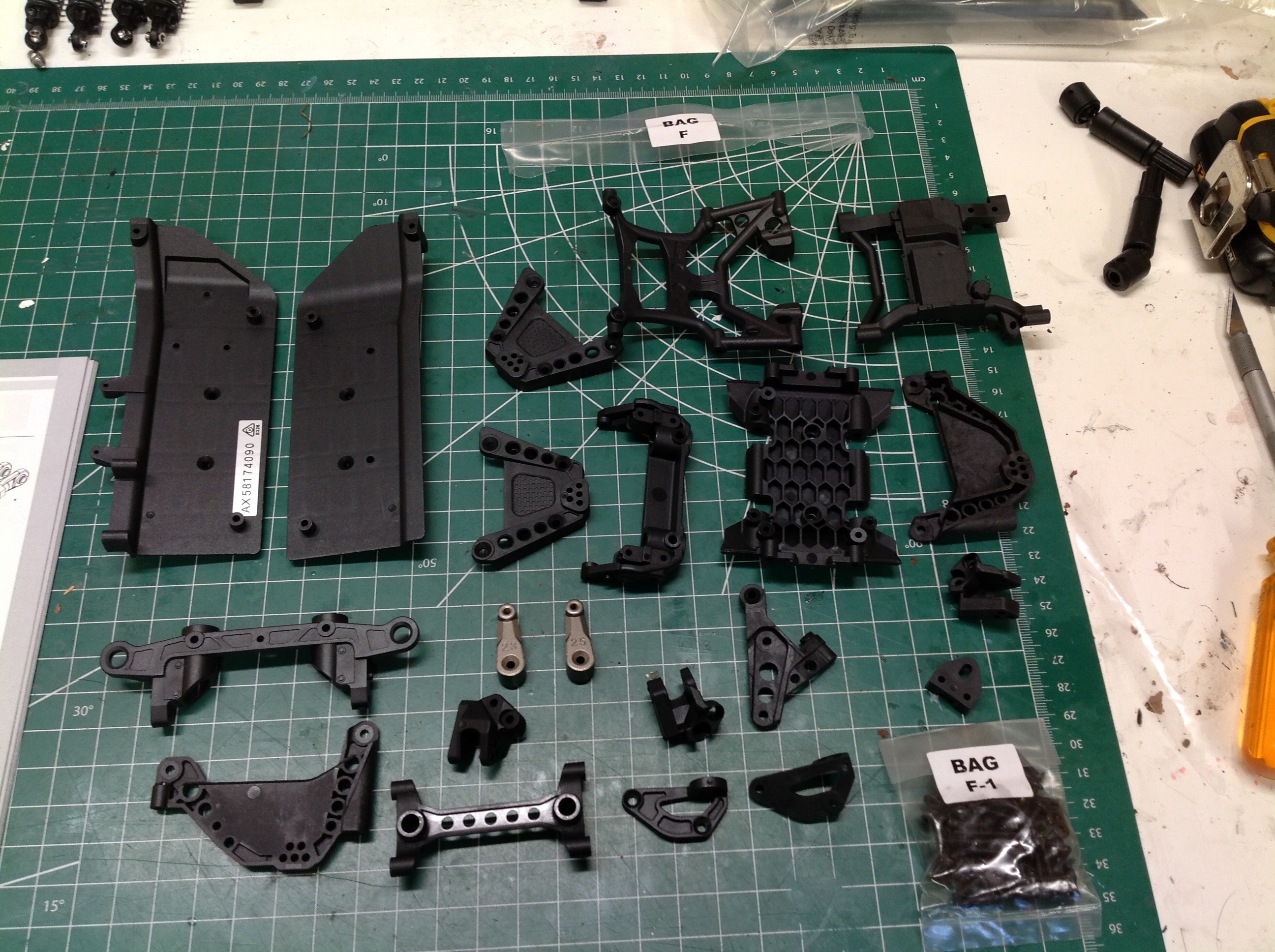
Now that all the sub-assemblies have been built, we can finally start on
the main chassis. The F bags contain the massive pile of plastic
that will make up all the attachments to the chassis rails.
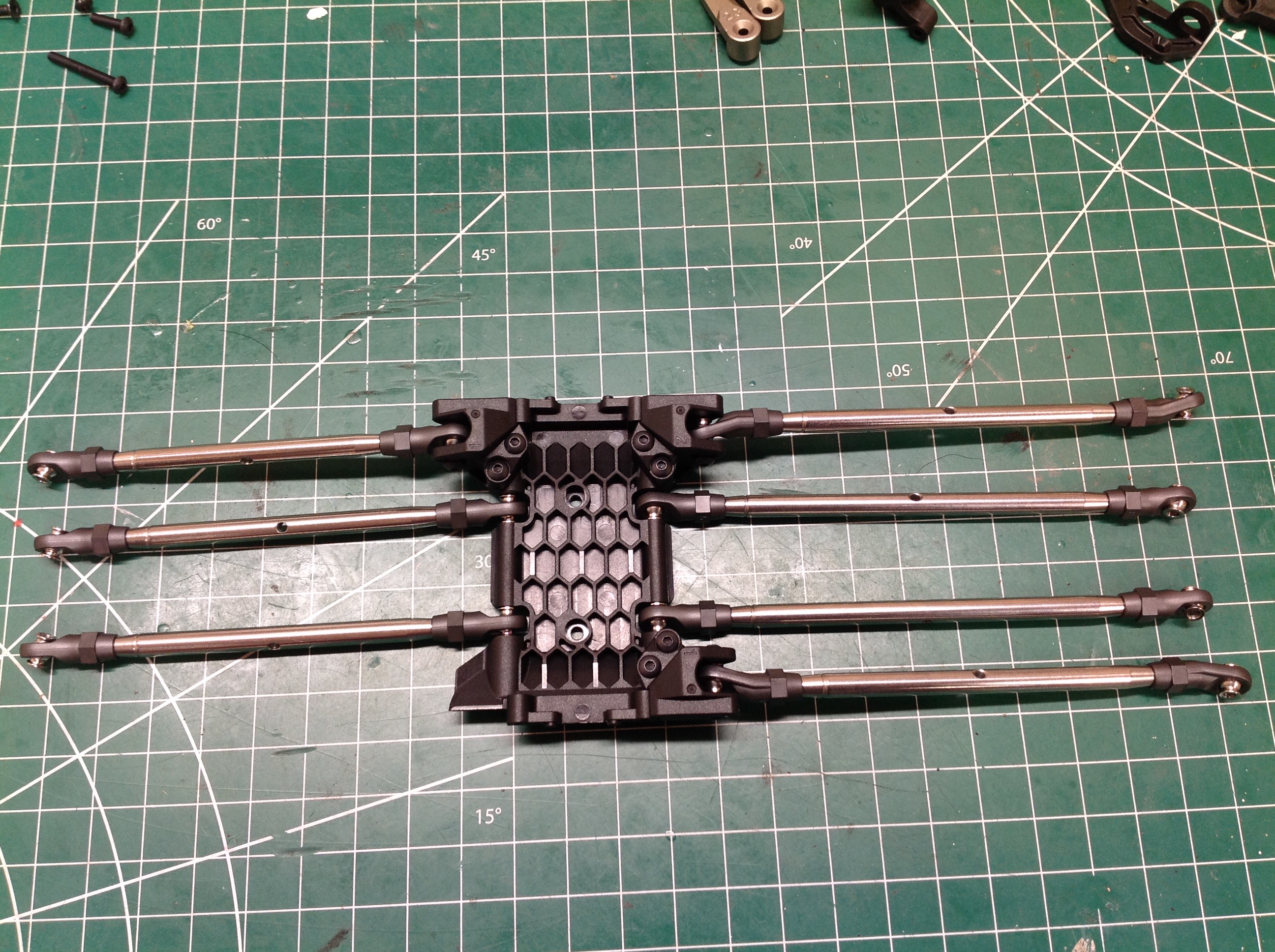
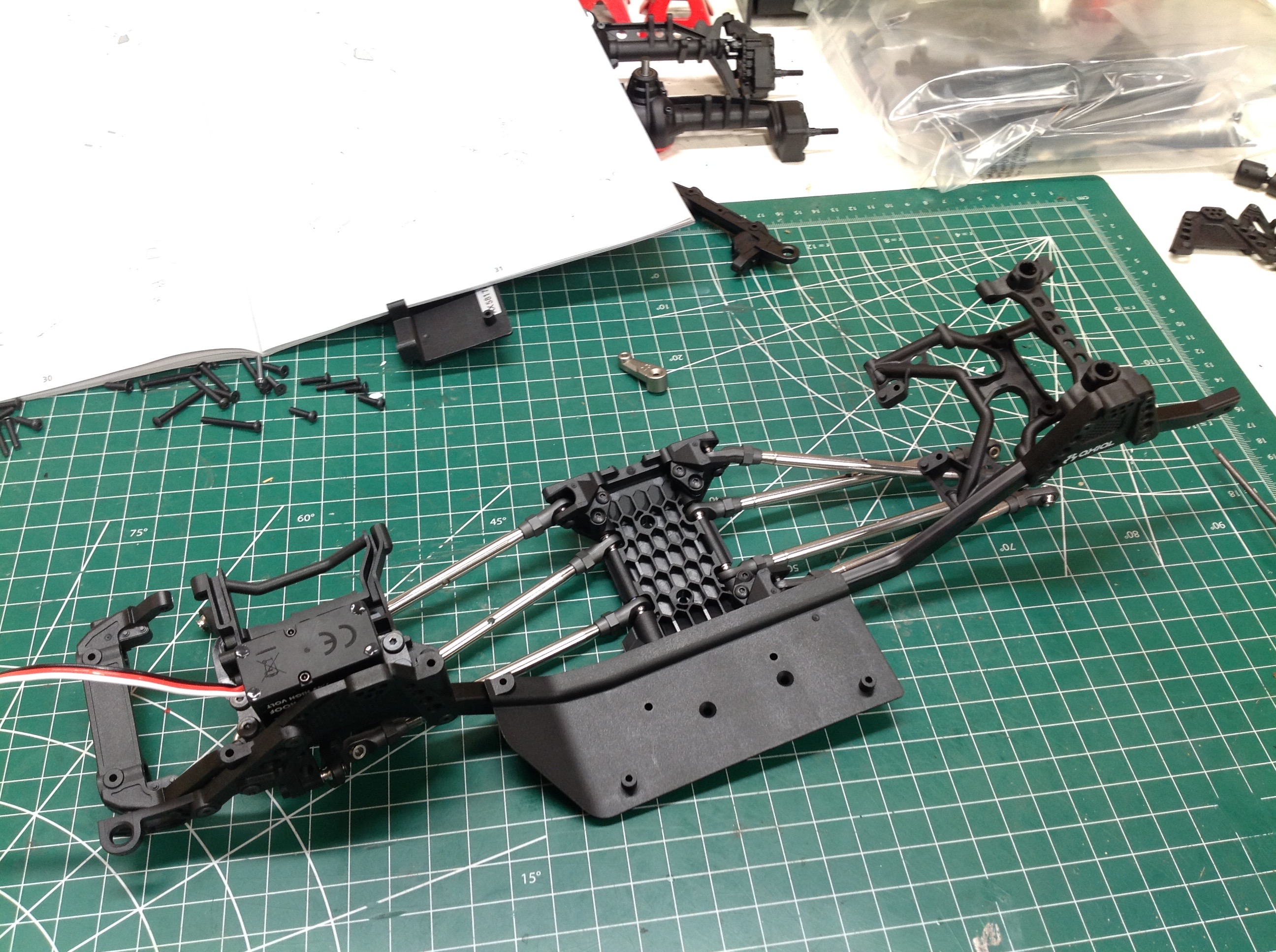
The first thing to do is attach the suspension links to the skid
plate. The skid plate has a flat bottom and all seven links attach
in roughly the same plane although the upper links are a tad
higher. The attachments for the upper links are on separate
plastic blocks with three separate mounting position choices.
Changing out the blocks entirely would allow for different suspension
geometry.
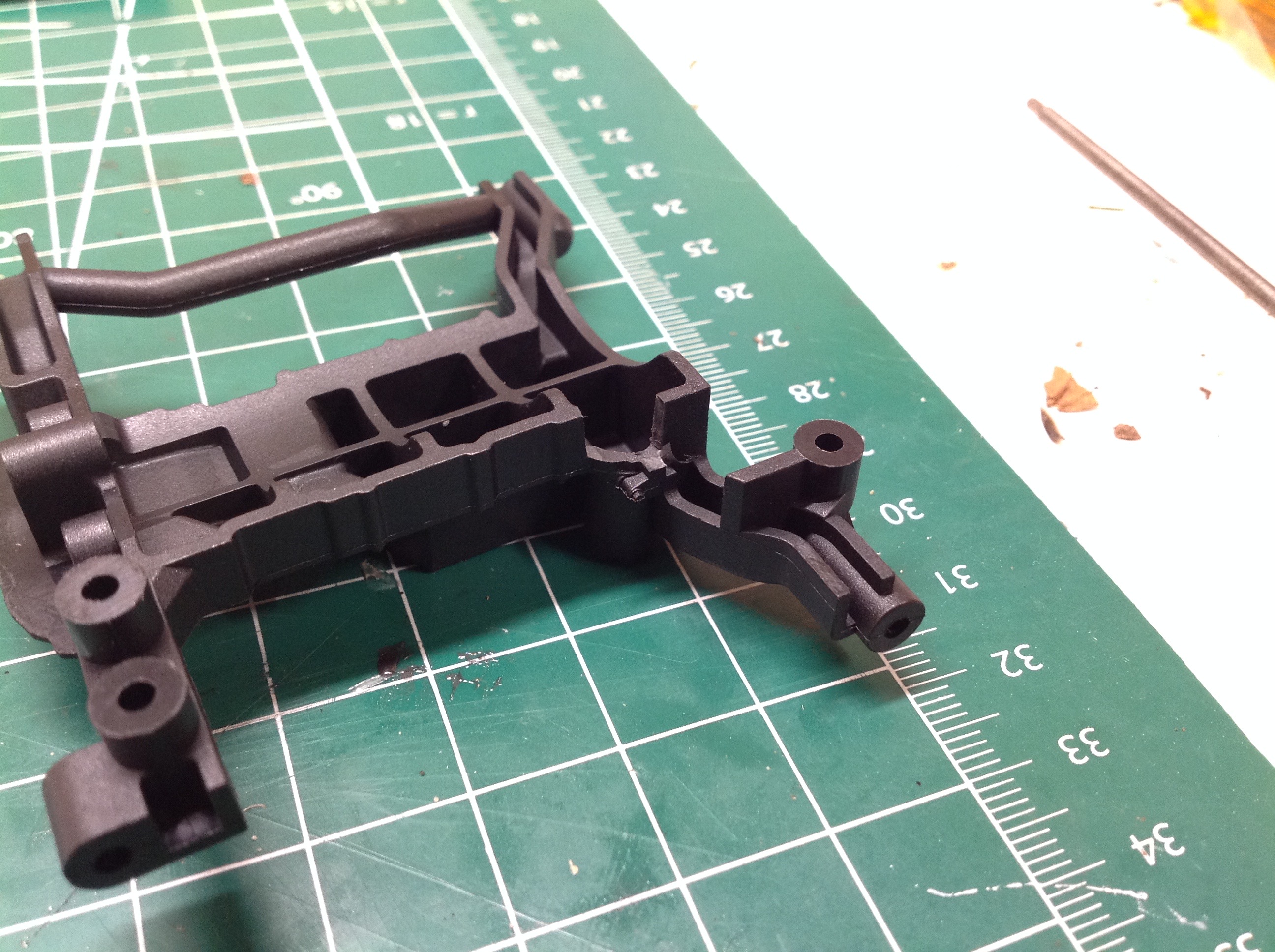
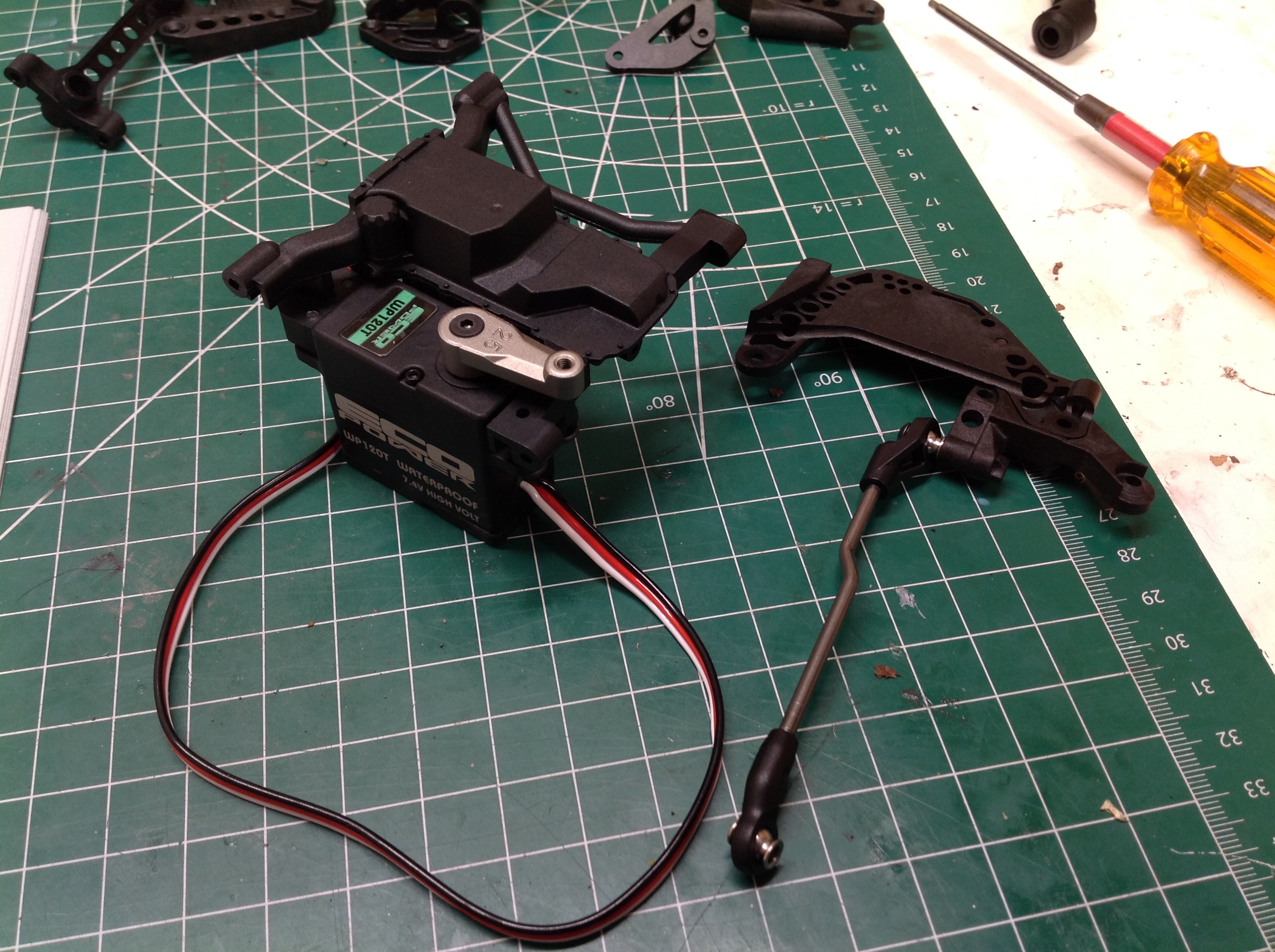
The front cross member supports the steering servo. I chose a high
torque, waterproof servo from Eco-Power. The right hand picture
shows the installed servo with the included metal servo horn as well as
the panhard bracket.
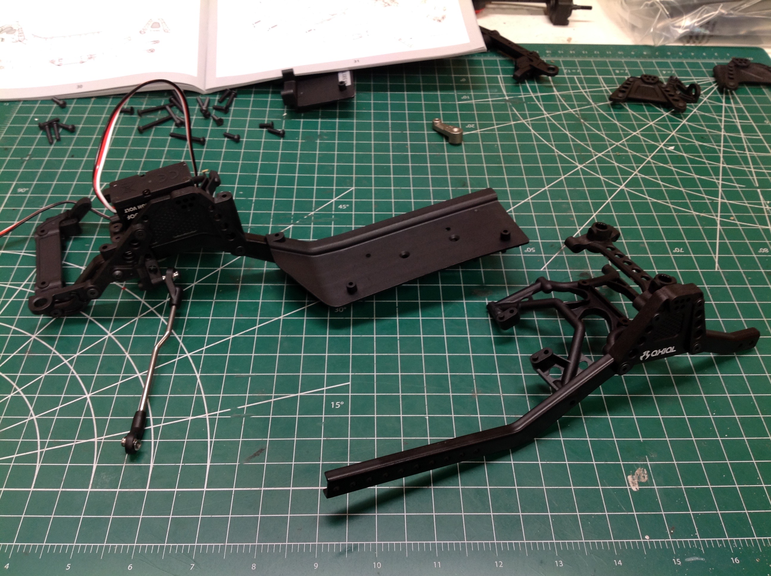
The chassis rails are split front-to-back to allow for an adjustable
wheelbase. We start by attaching the front steering cross member,
bumper bracket, shock hoop, and slider to the front left rail. A
cross member, a shock hoop, a stiffener, and a slider are attached to
the rear left rail and then both rails are joined at the skid plate as
shown. This multi-piece frame isn't my favorite since it reduces
strength and increases flexibility, but I understand its utility.
It looks like this version is built with the longest available wheelbase
and five more shorter options are available.
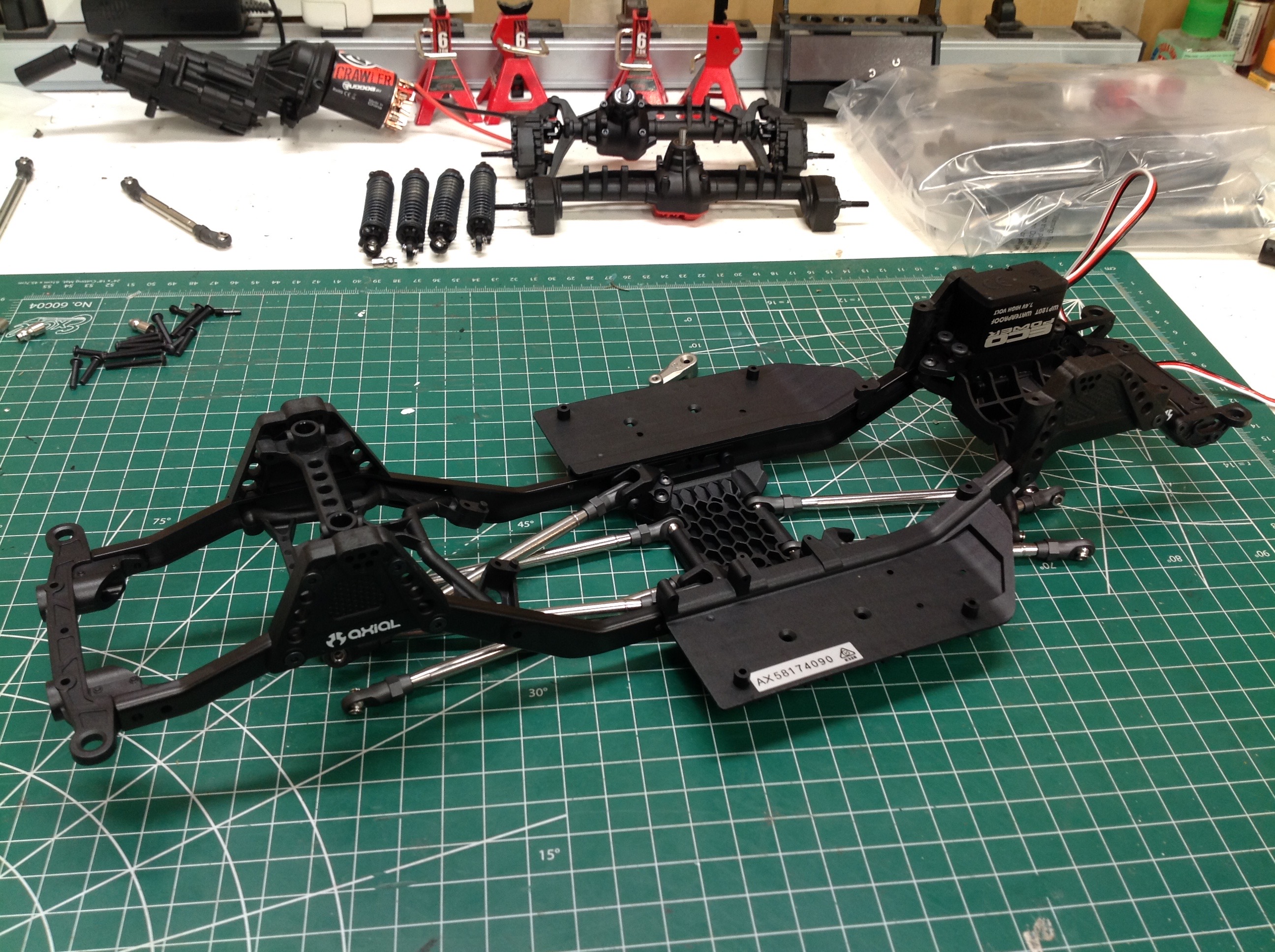
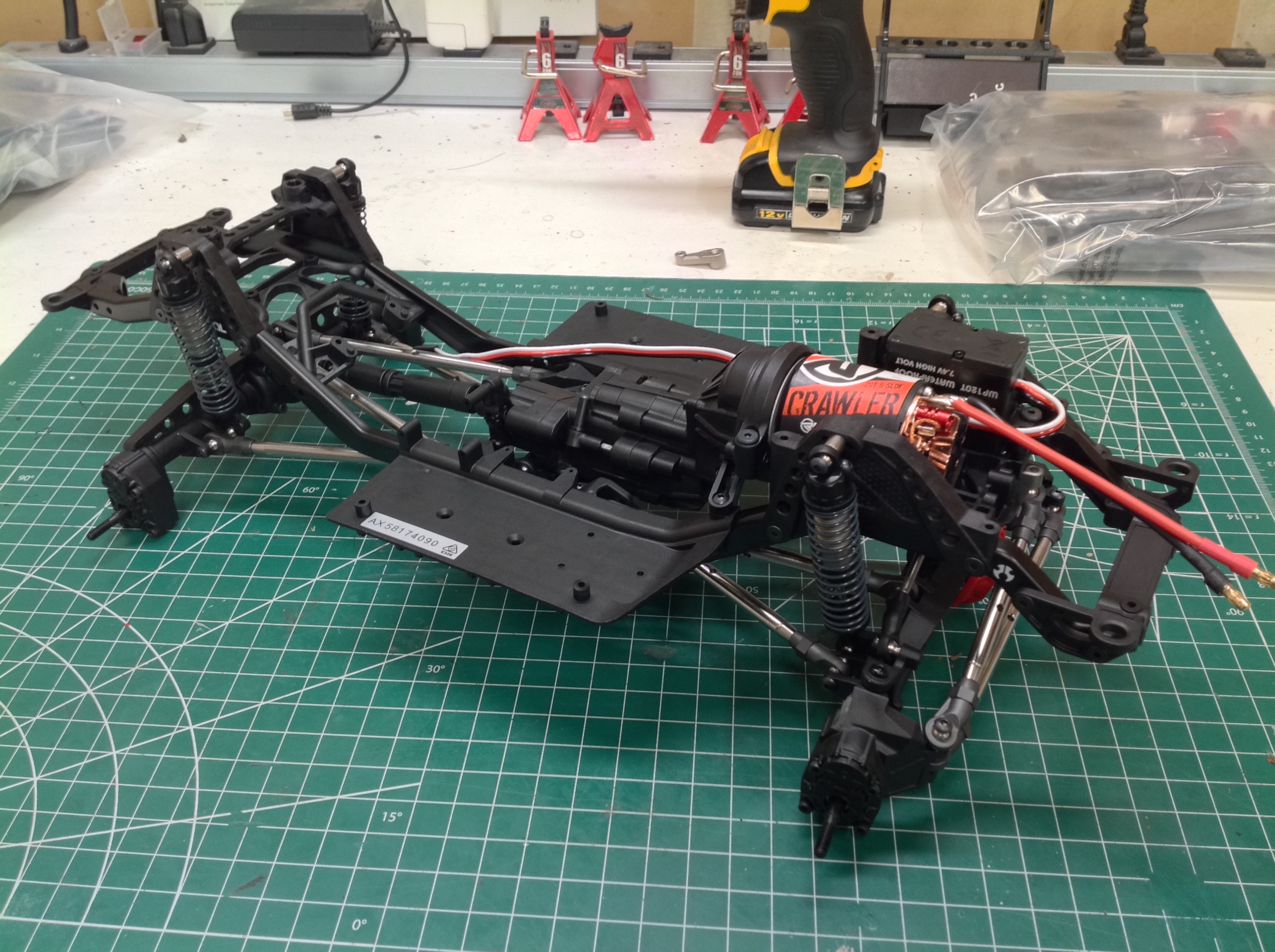
After the identical steps are performed on the right side, the motor and
transmission assembly can be installed as shown. They mount with
only 4 screws spaced widely for stability.
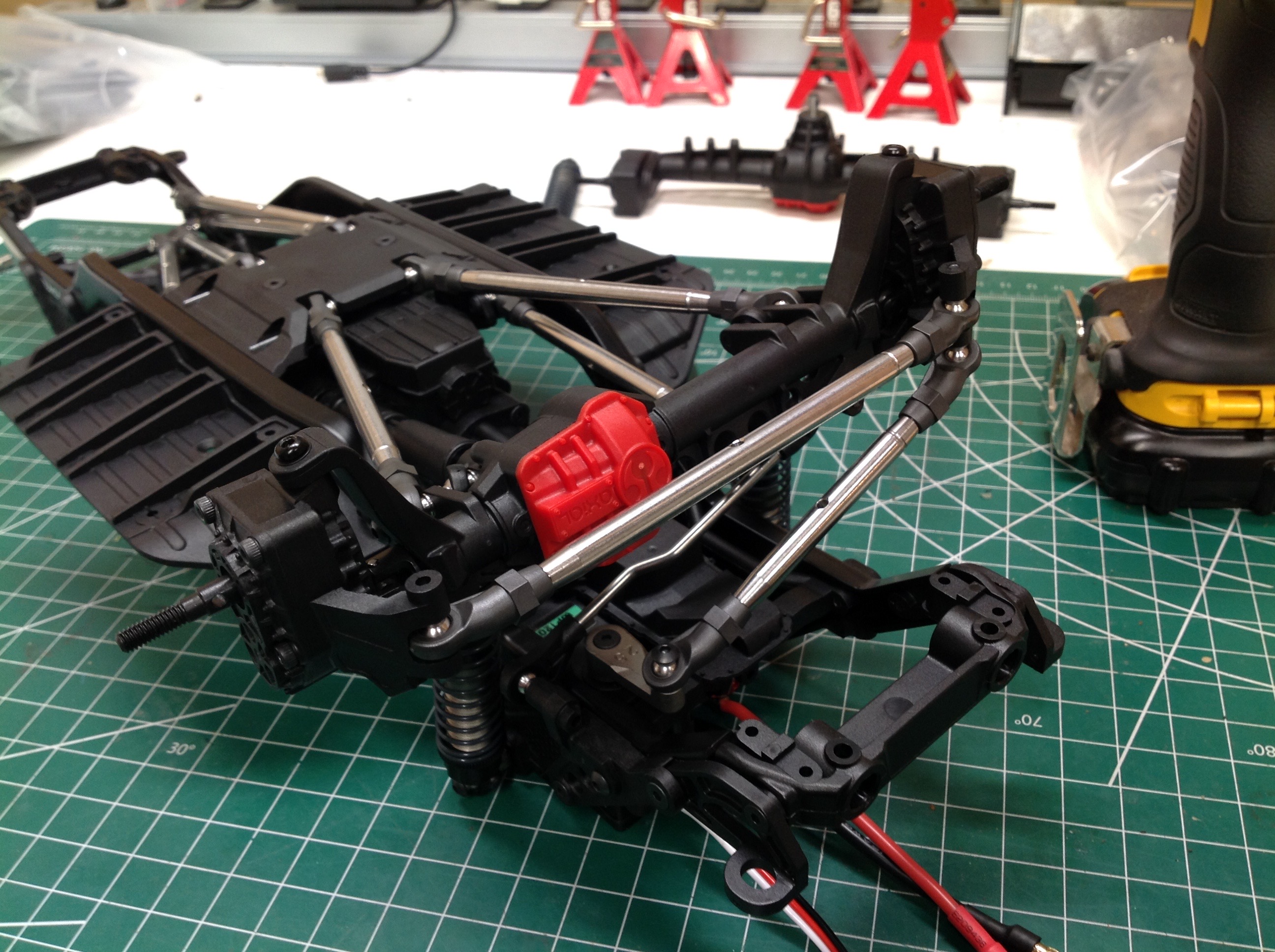
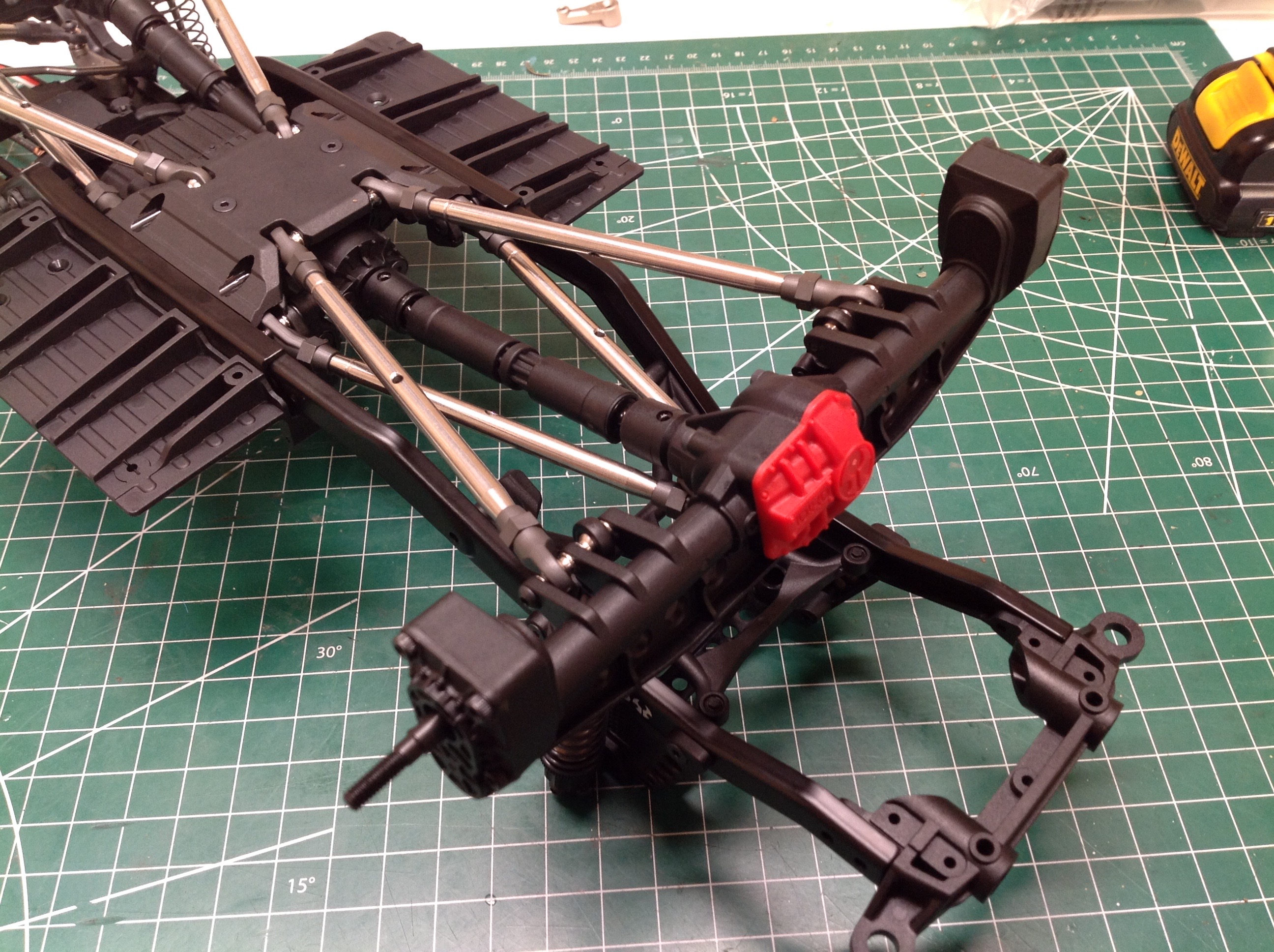
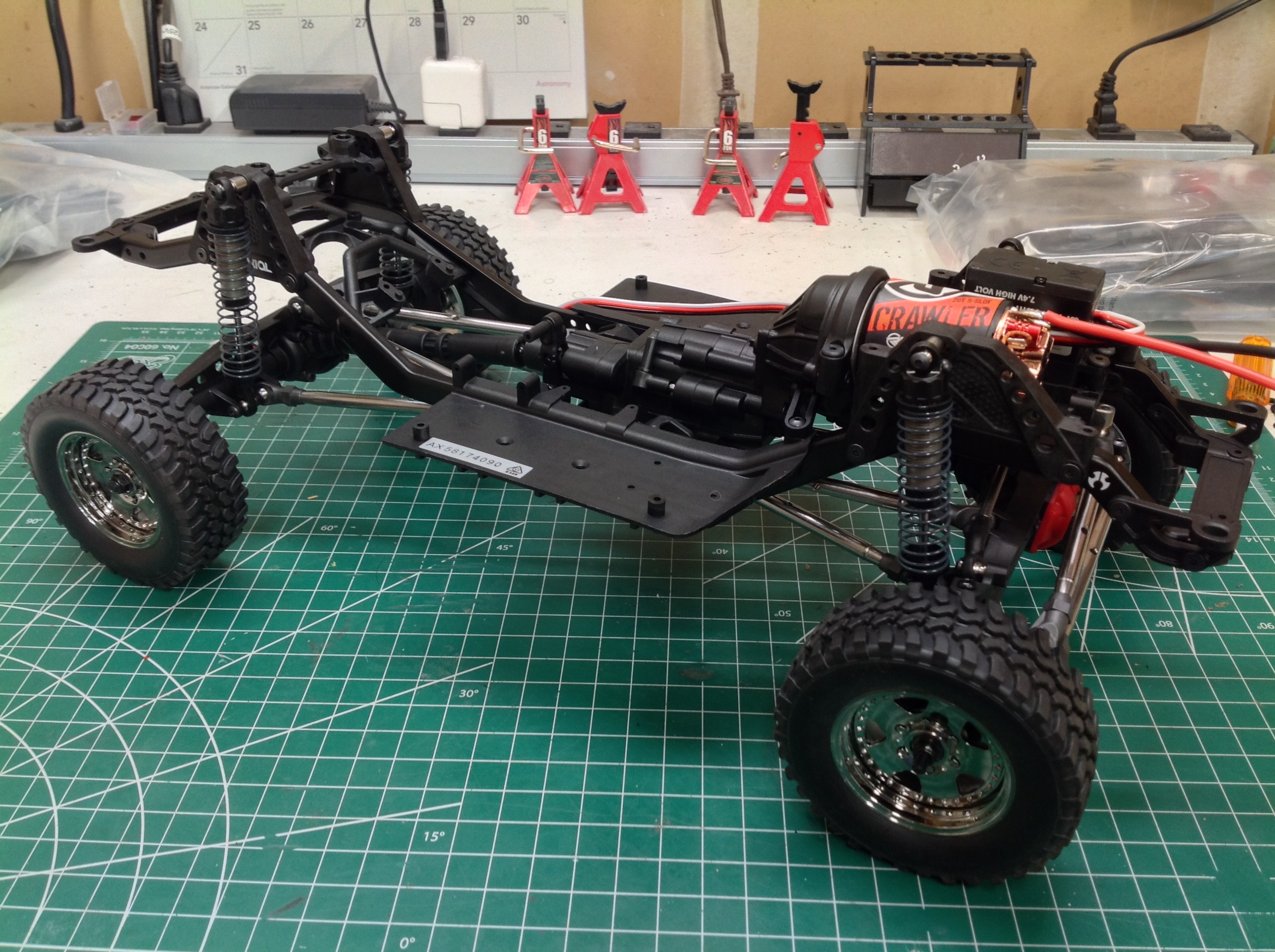
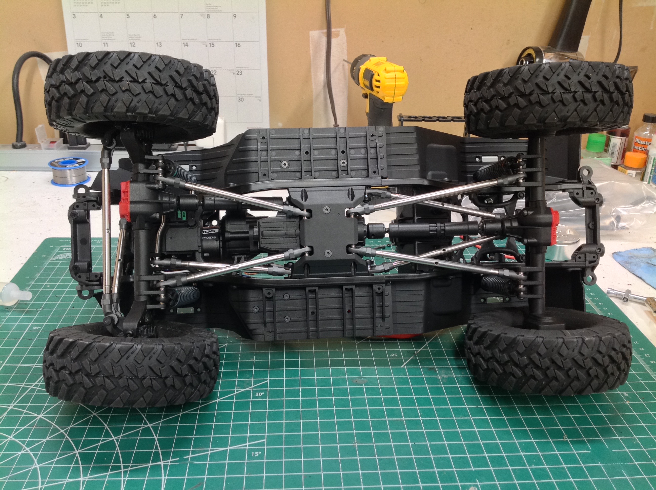
Now the axles can be mounted. The left hand image shows the front
axle mounted with the panhard rod and steering links. The right
hand image shows the rear axle with four triangulated links. The
shocks have also been installed, though they are difficult to see in
these pictures with the chassis inverted. The drive shafts have
also been connected.
Here it seems like the chassis is done, but there is actually quite a
bit still to add. On the right I've installed some wheels and
tires from a Tamiya CC-01 just to see how ridiculous it would
look. The answer: very.
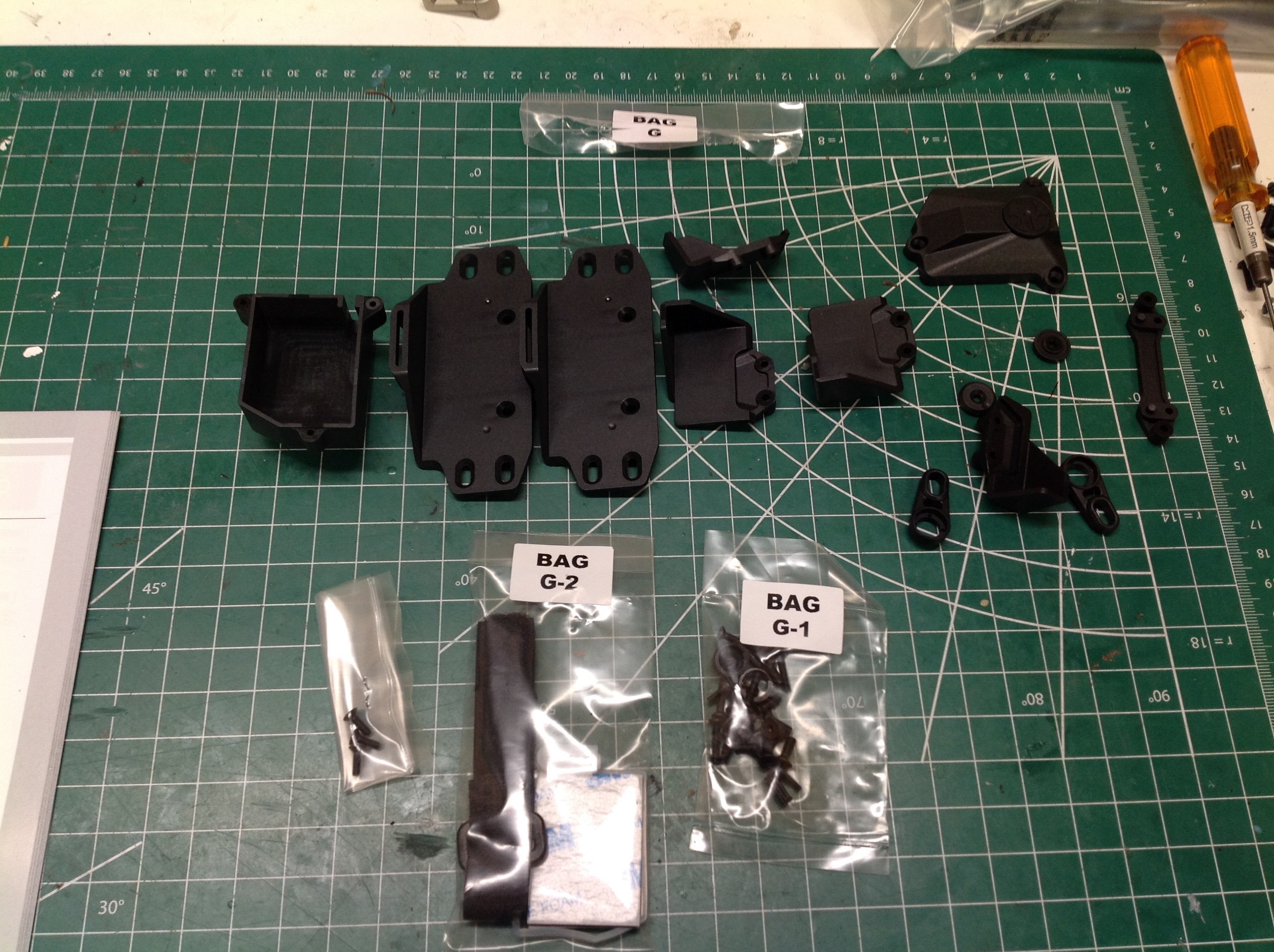
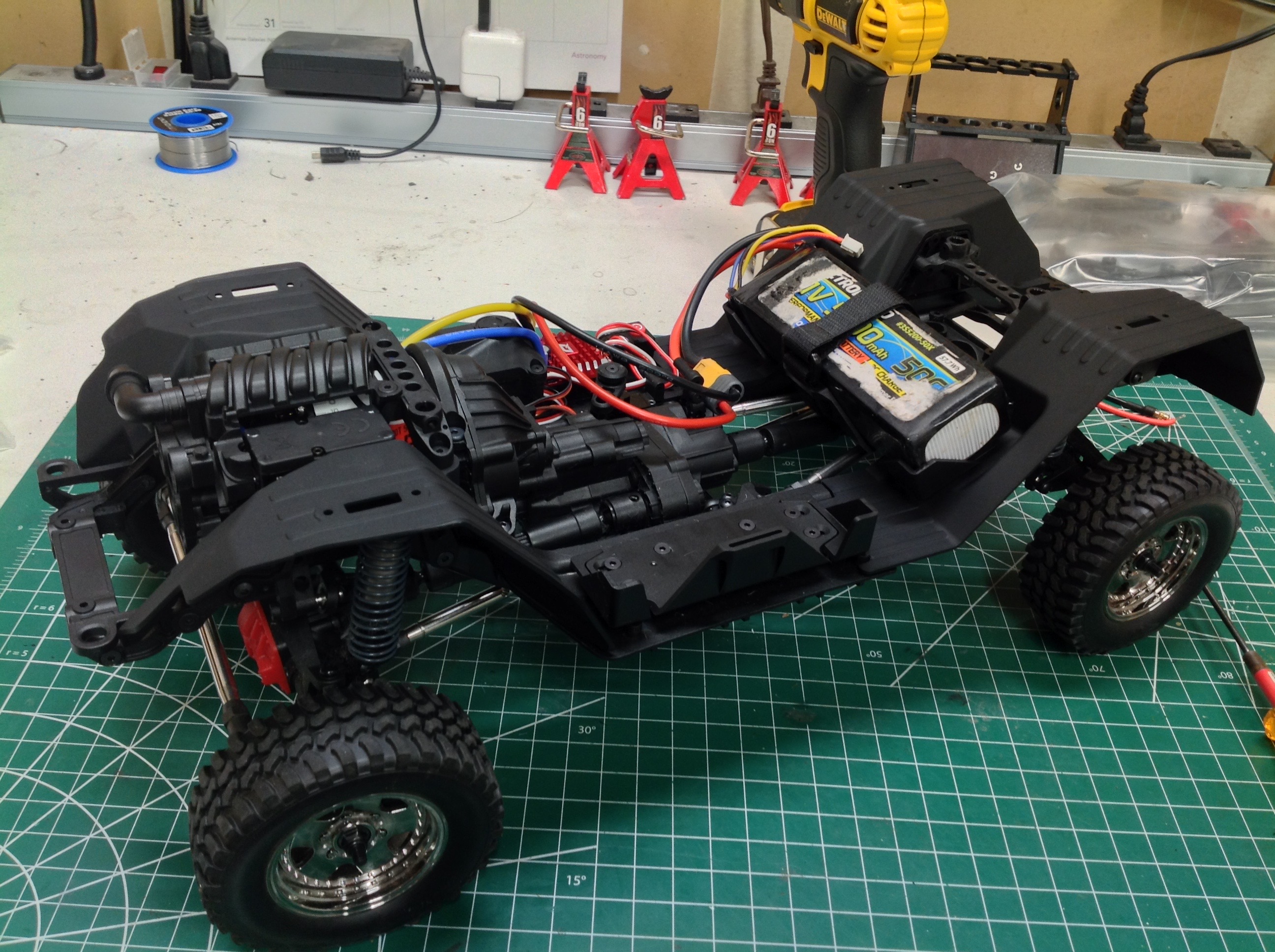
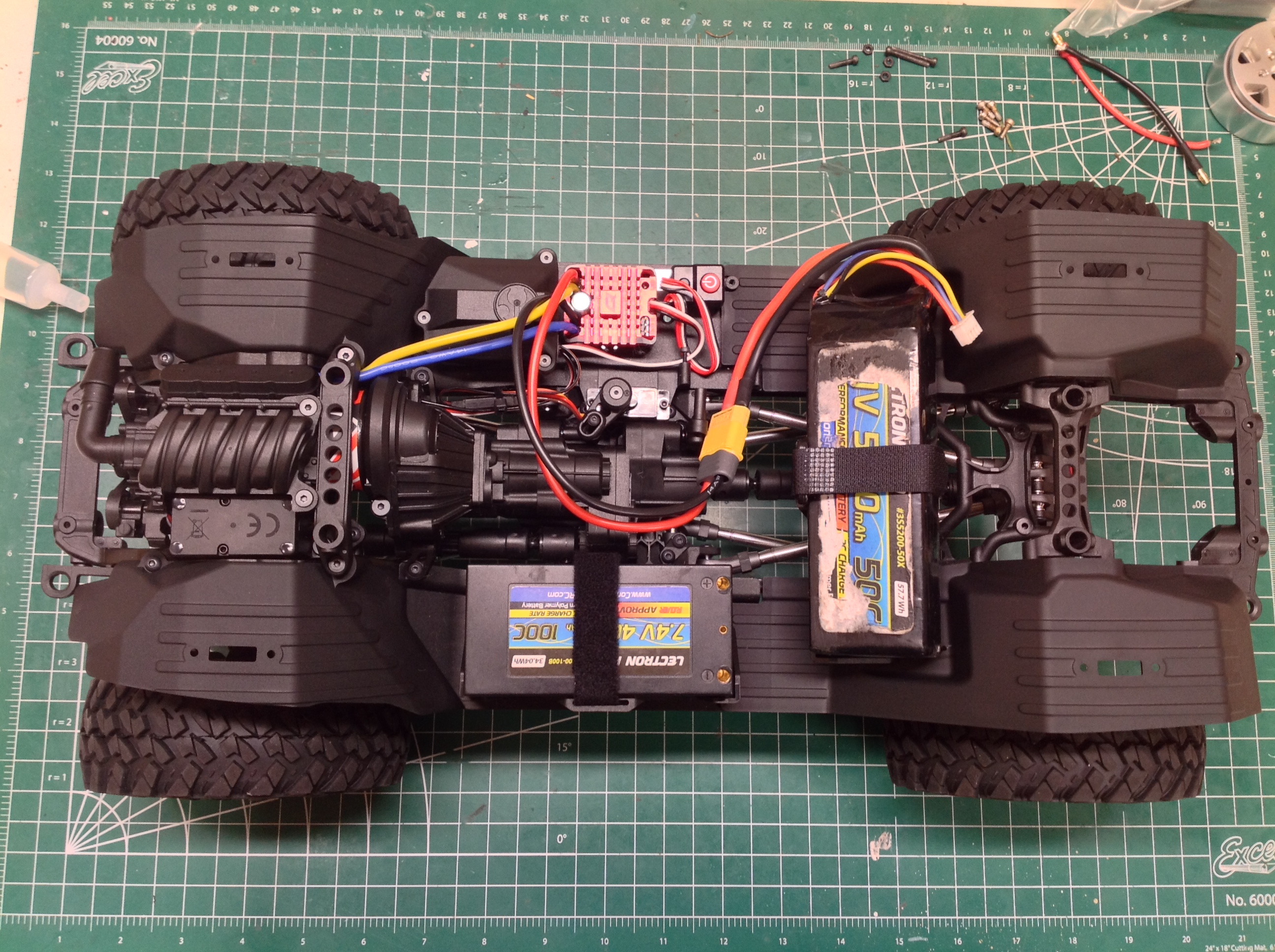
The G bags contain the plastic parts for the battery tray(s) and electronics box.
There are two adjustable battery trays to choose from. A full size
tray sits laterally across the rear of the chassis and a shorty tray
sits on the left slider. Nothing stops you from using both
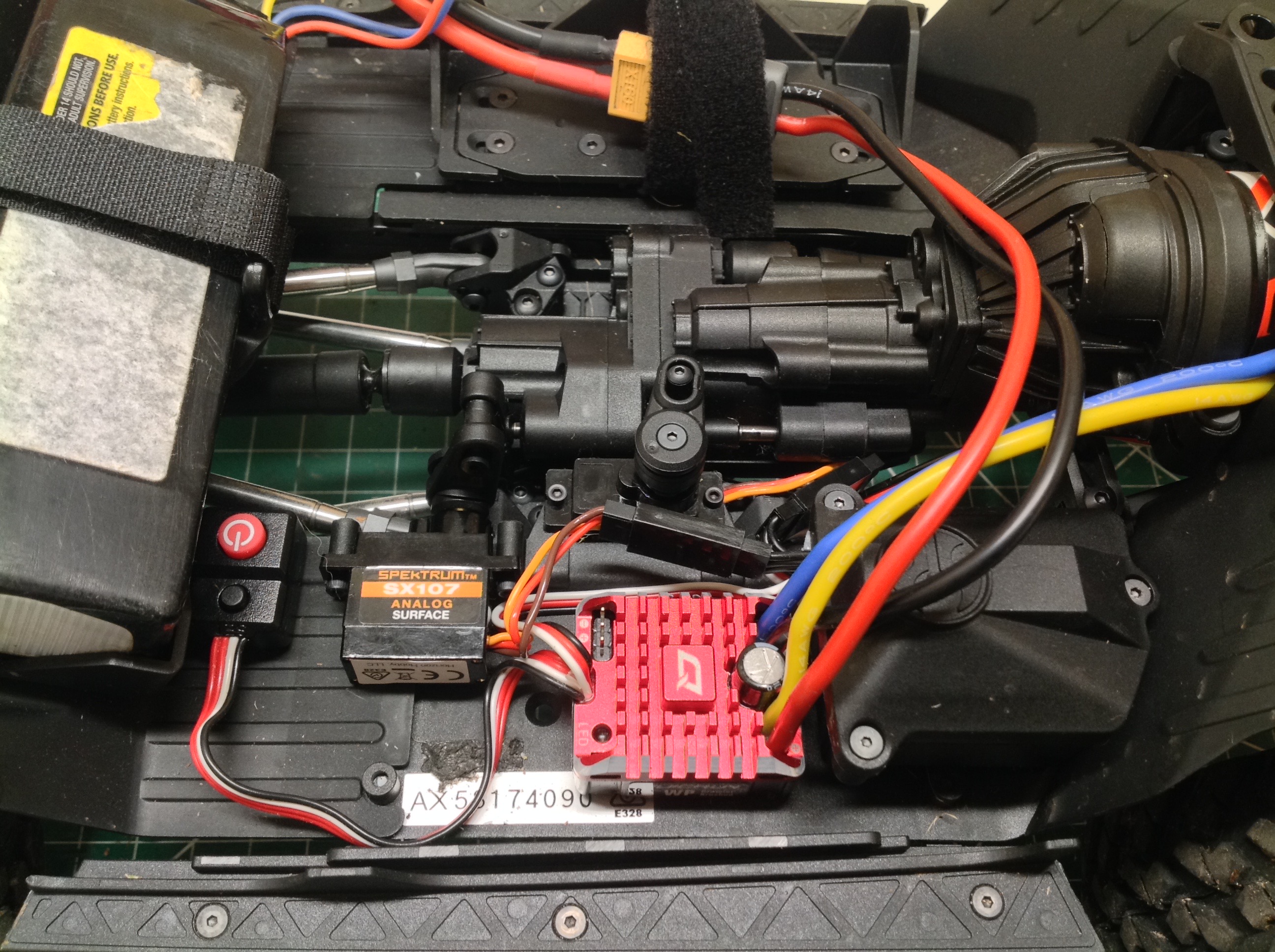
which I've done here. On the right side I've installed the ESC and
the receiver sits inside the waterproof box. The box is really
small so you better have a small receiver if you want it to fit. I
used a 5-channel Spektrum unit so I'll be able to control both micro
servos and also a winch later. If you want both the dig and the
2-speed transmission operable, you need two micro servos. The
servo saver arm required comes with the servos which pretty much forces
you to use Spektrum branded servos. This is one of the biggest
complaints I've heard about this model. At this point the rolling chassis is complete and the model
is totally drivable.
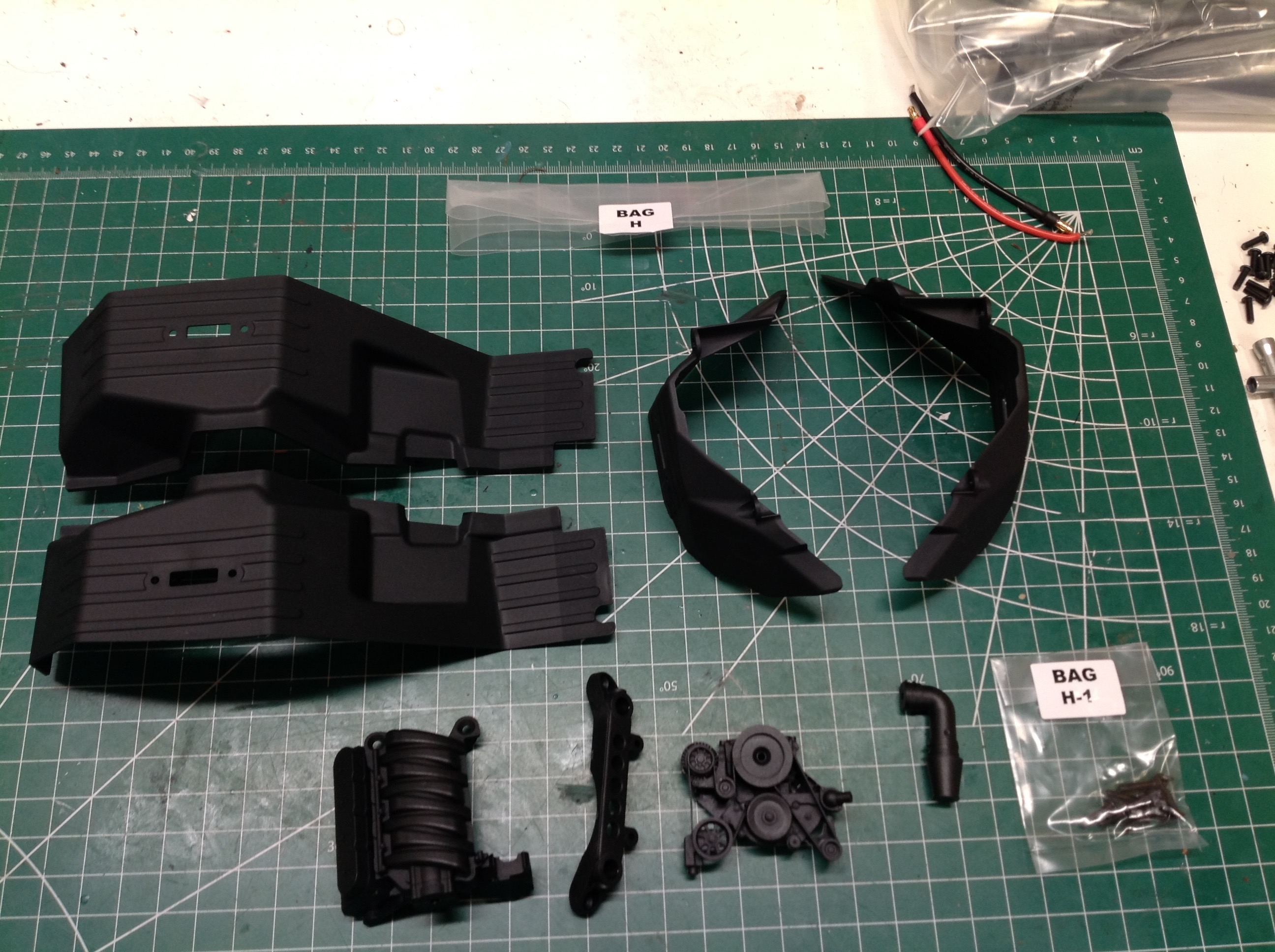
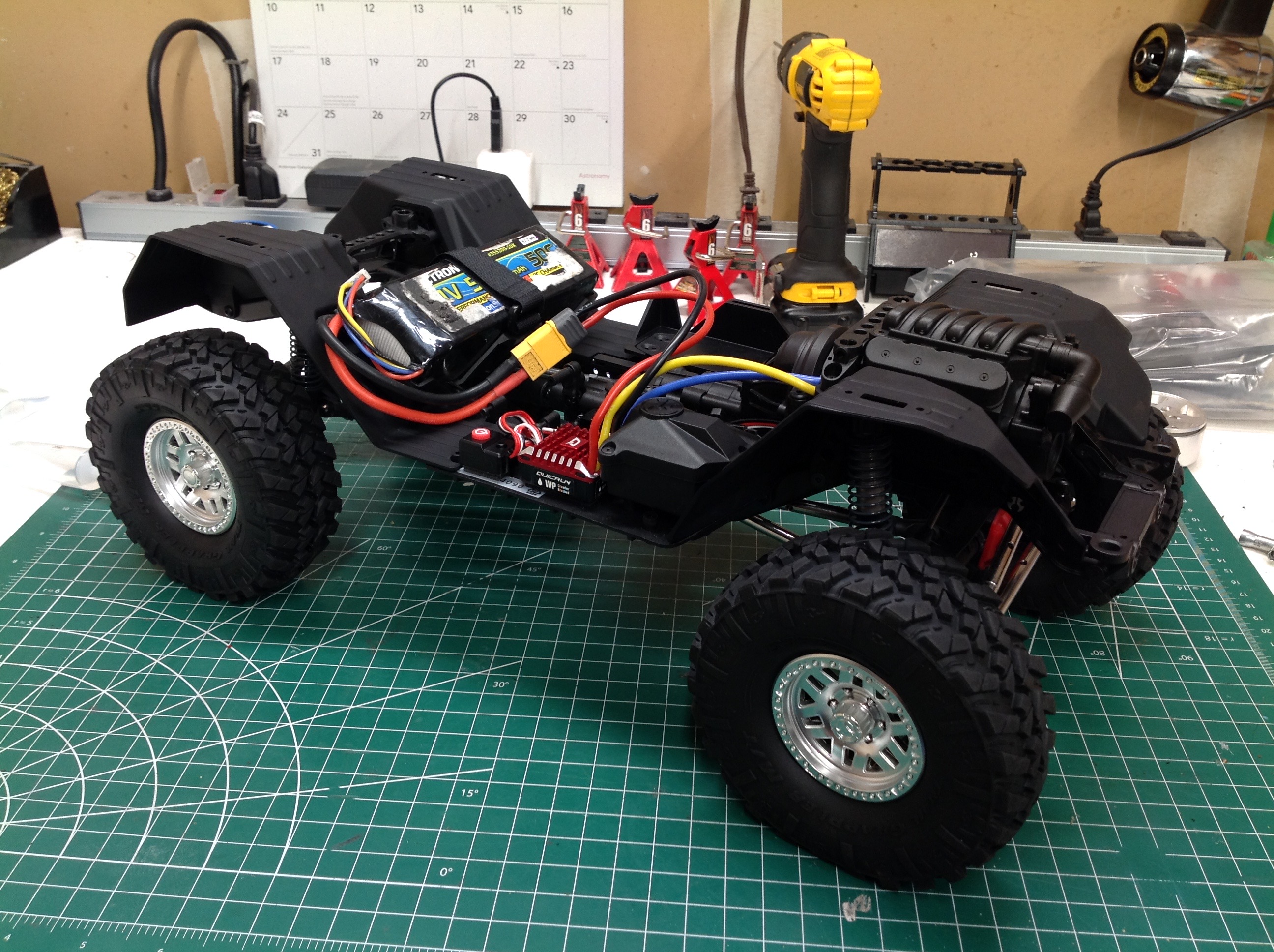
The H bags contain the 4 large inner fenders and the parts for the scale
engine. The fenders have openings for rock lights, but as of this
writing Axial had not released any. Seems like a major
oversight. The plastic intake manifold and pulleys sit over the
top of the motor and make this look like a real engine. It would
look more real if I could be bothered to paint it. However, since
the body does not have an opening hood this engine can never be
seen. There is only one valve cover on the engine, the other is
cut out to allow room for an oversize steering servo. I'm sure
people will be 3D printing their own opposite valve cover to complete
the look.
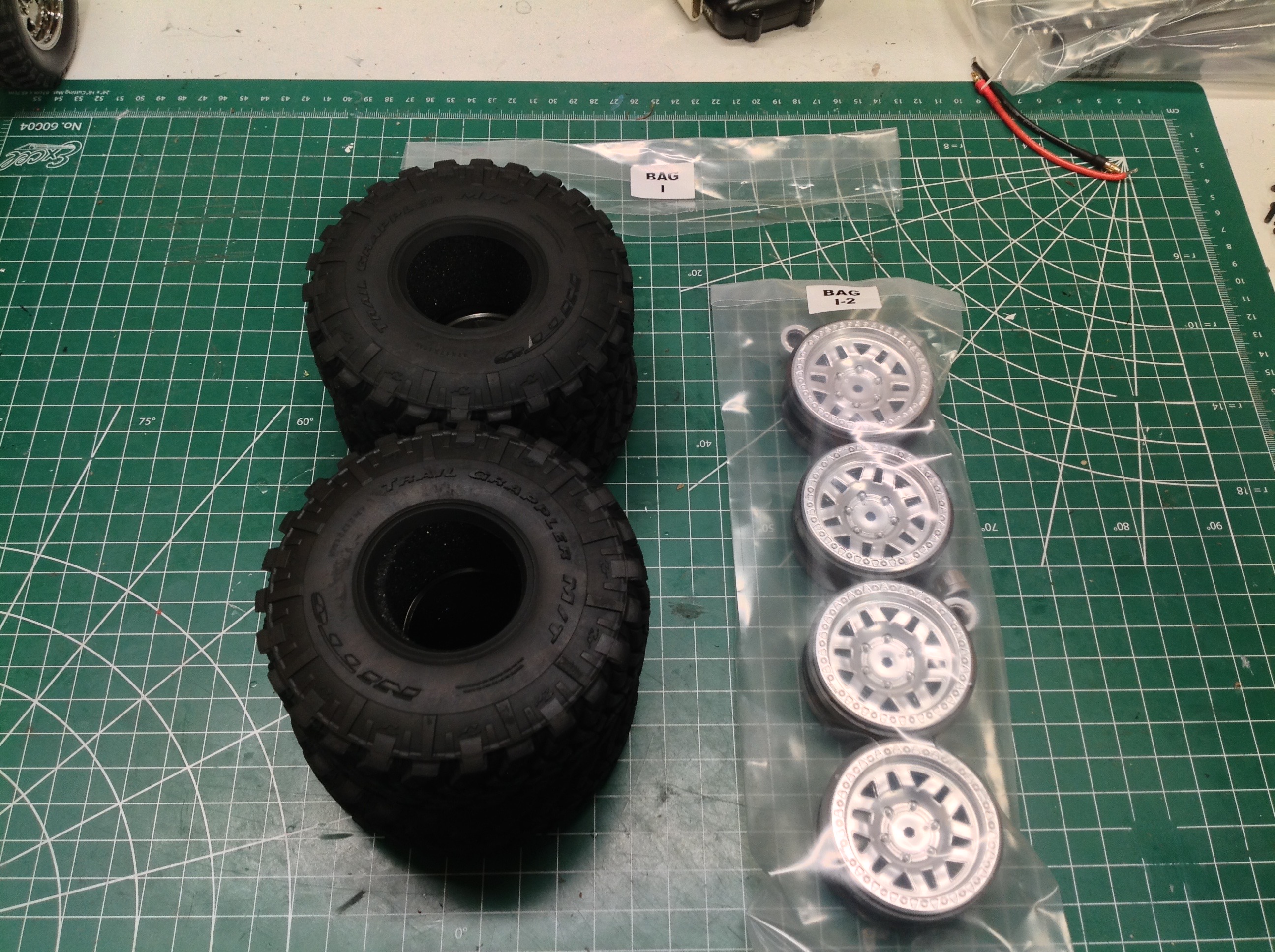
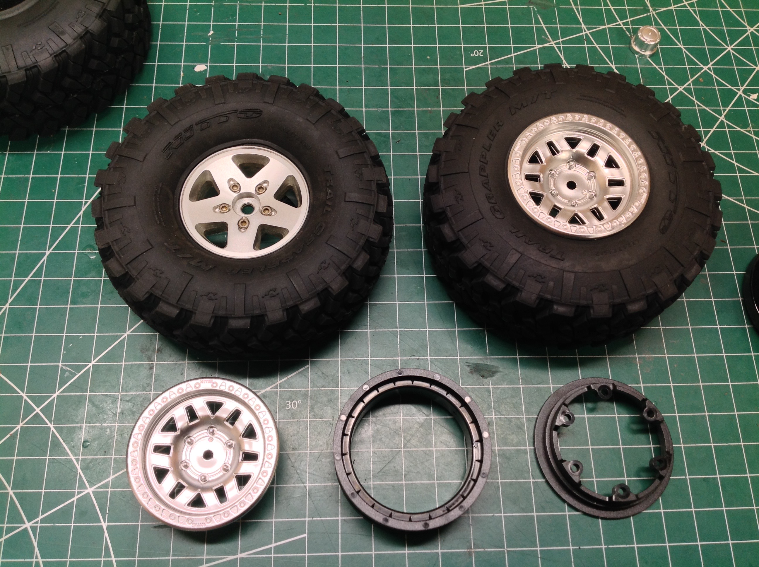
The I bags are the last for the chassis and include the plastic beadlock
wheels and the licensed Nitto Trail Grappler tires. I attempted
to use some aluminum 5-spoke Jeep wheels as shown on the right, but they
didn't fit around the portal axles, so I reverted back to the plastic
stock wheels which actually look very nice.
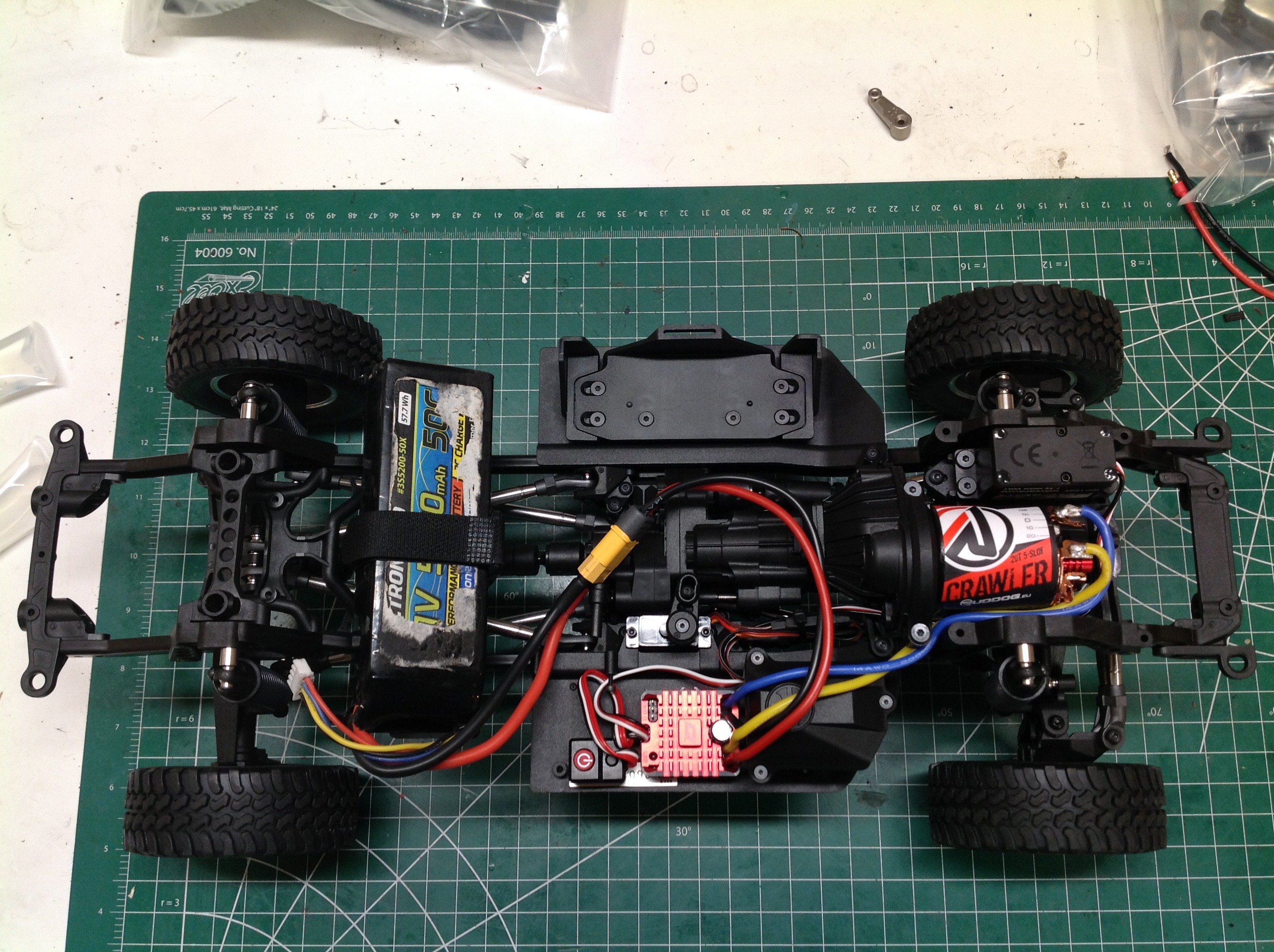
With the wheels and tires added the chassis is complete. The
photos show the chassis from above and below. The right hand
picture shows both optional battery locations in use which should result
in a run time lasting the whole day.
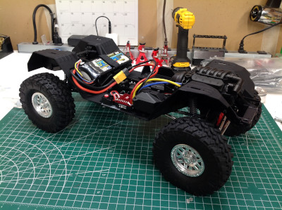
The completed chassis.
©2020 Eric Albrecht