Axial SMT10 Project
Page 1: Chassis Assembly
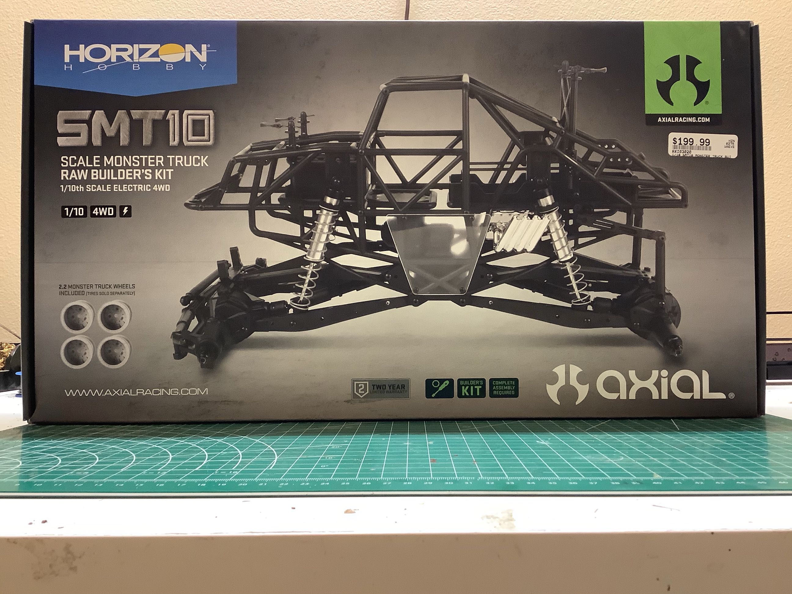
Without giant tires or a body to take up space, this body is pretty
small for a 1/10 scale monster truck. A set of wheels is included
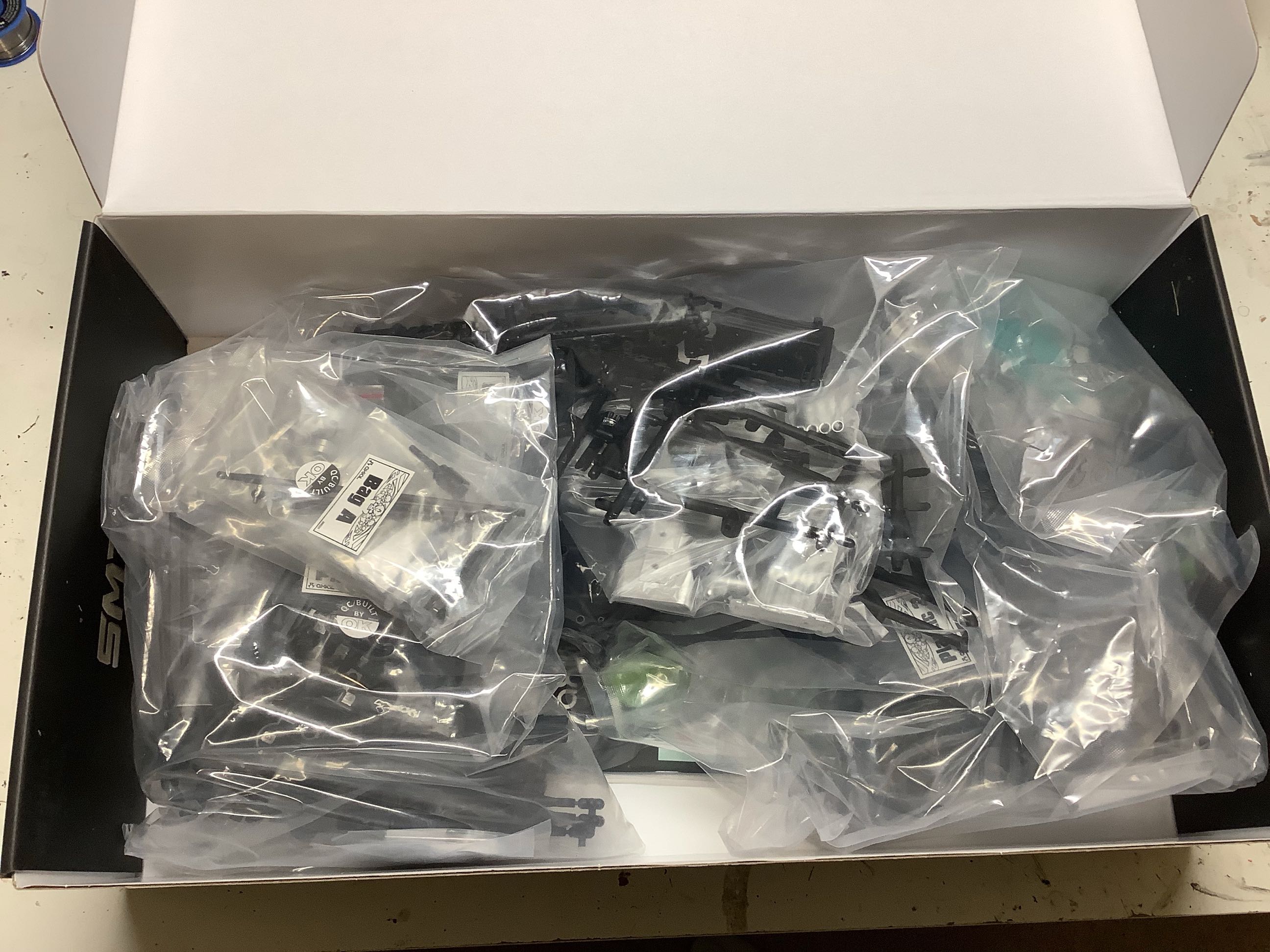
although I ended up using something different. The bags inside the
box correspond to sections of the instructions.
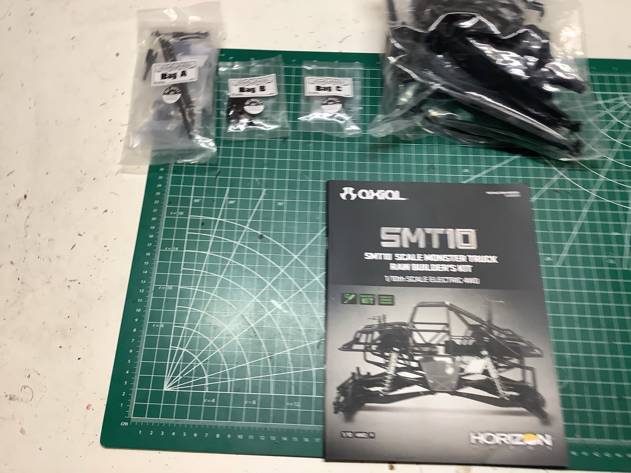
Here is a terrible picture of some of the bags and the manual prepared on my building table.
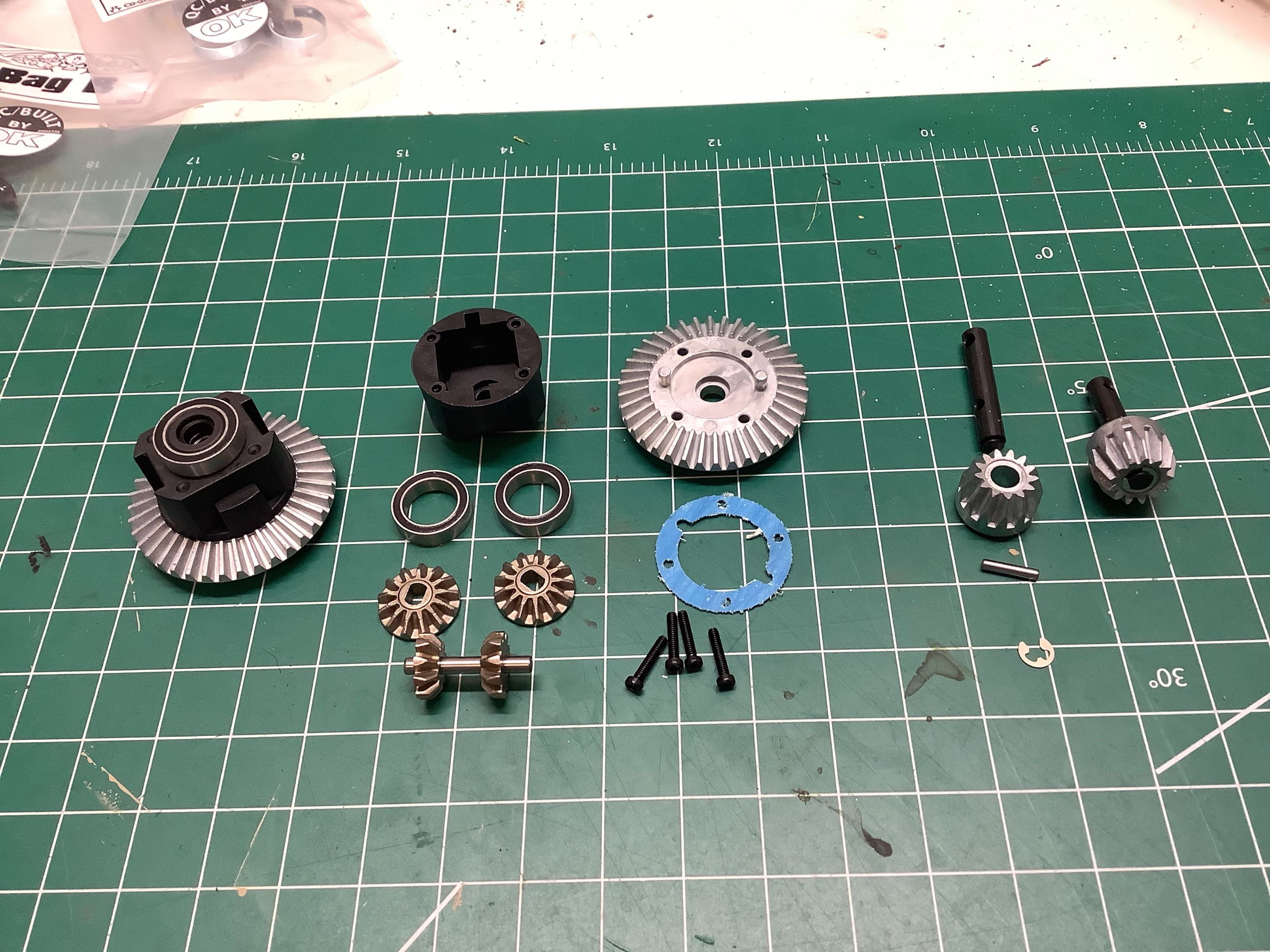
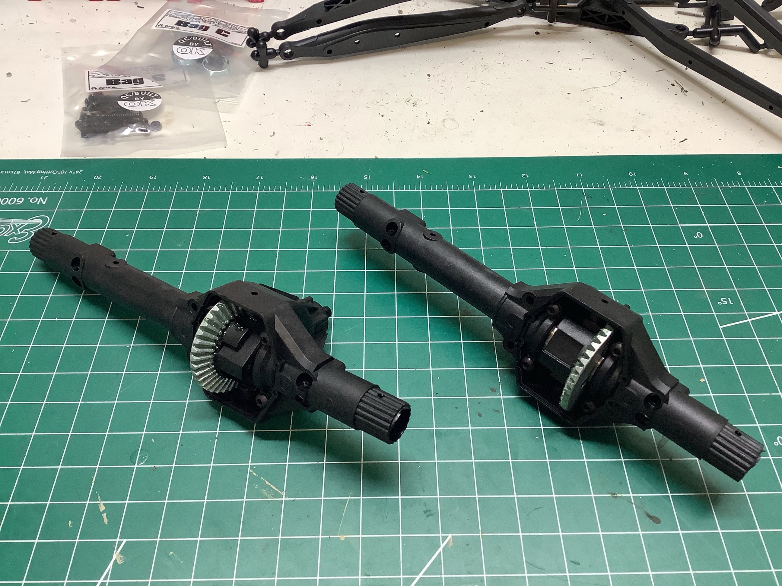
The build starts with the axles. The front and rear axles are
identical at the start which means the truck could be converted to four
wheel steer with some extra parts. The differentials are open with
4 spider gears and are intended to be greased, not filled. They
can be locked with an optional locker. Note the off center pumpkin
and the fact that the differential ring gears are installed in opposite
directions front and rear.
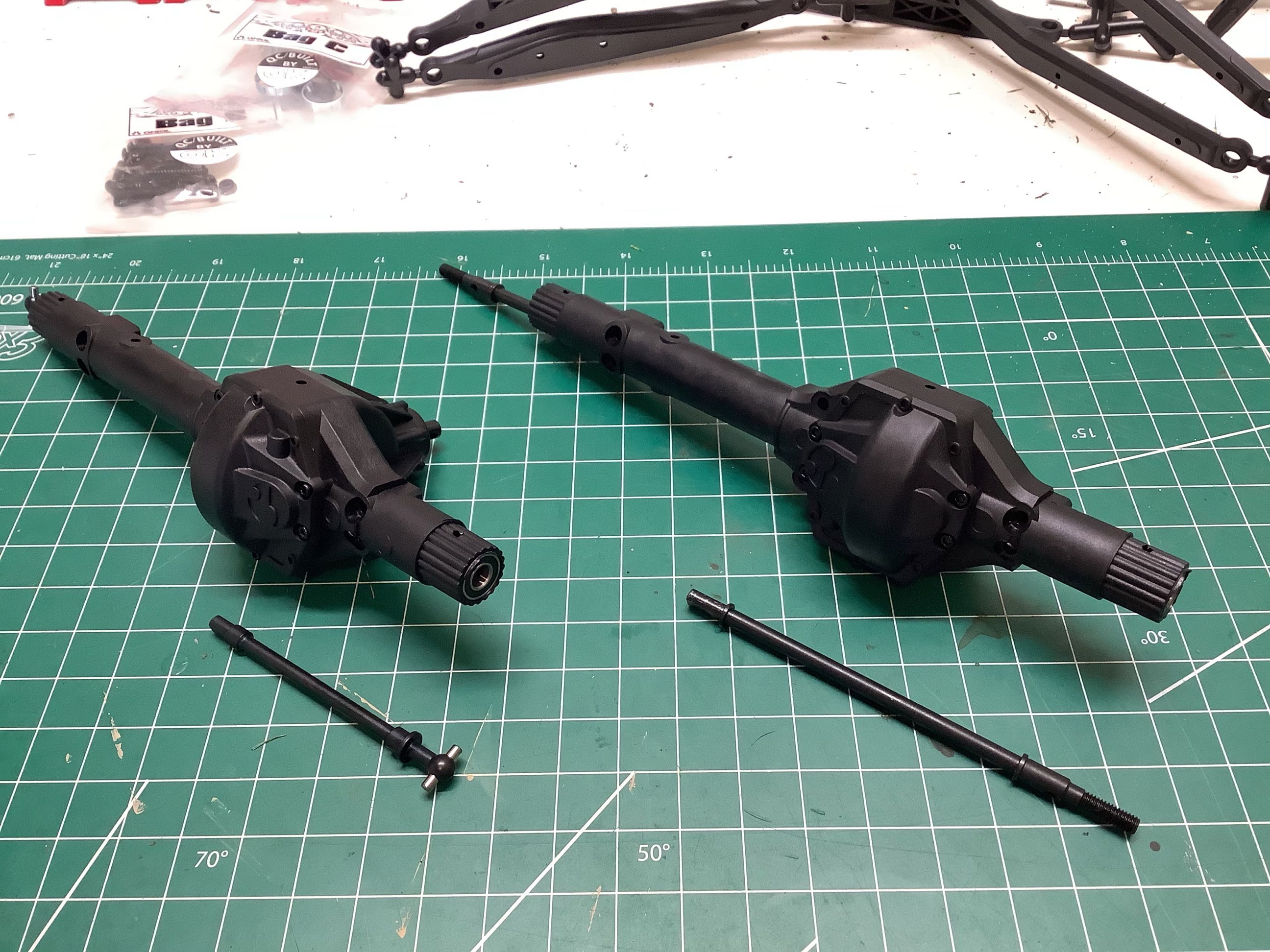
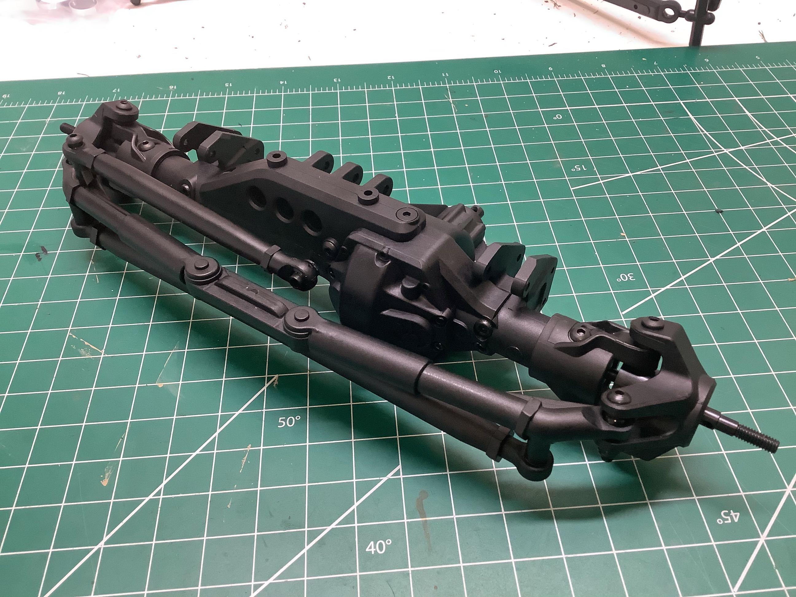
Now the front and rear axles start to be differentiated from each
other. The front axle shafts use dog bone ends (upgradeable to
universals) and the rear uses straight axle shafts as shown on the
left. On the right you can see that the front axle got C-hubs
installed while the rear just uses straight extensions with additional
bearings. These are Axial AR66 axles, the same used on the Bomber.
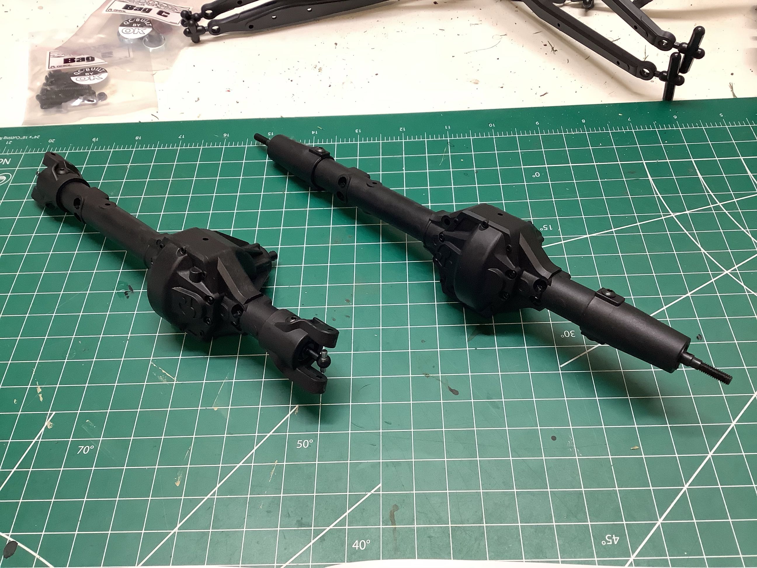
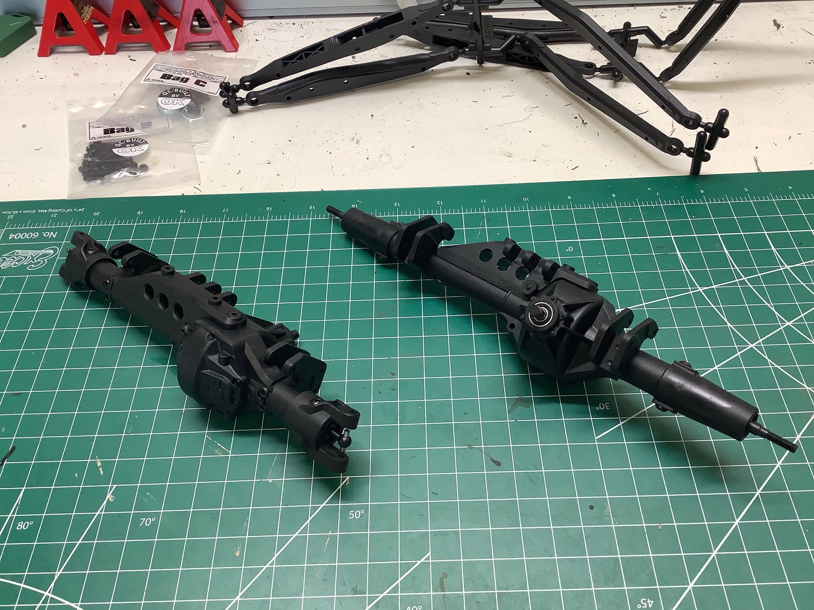
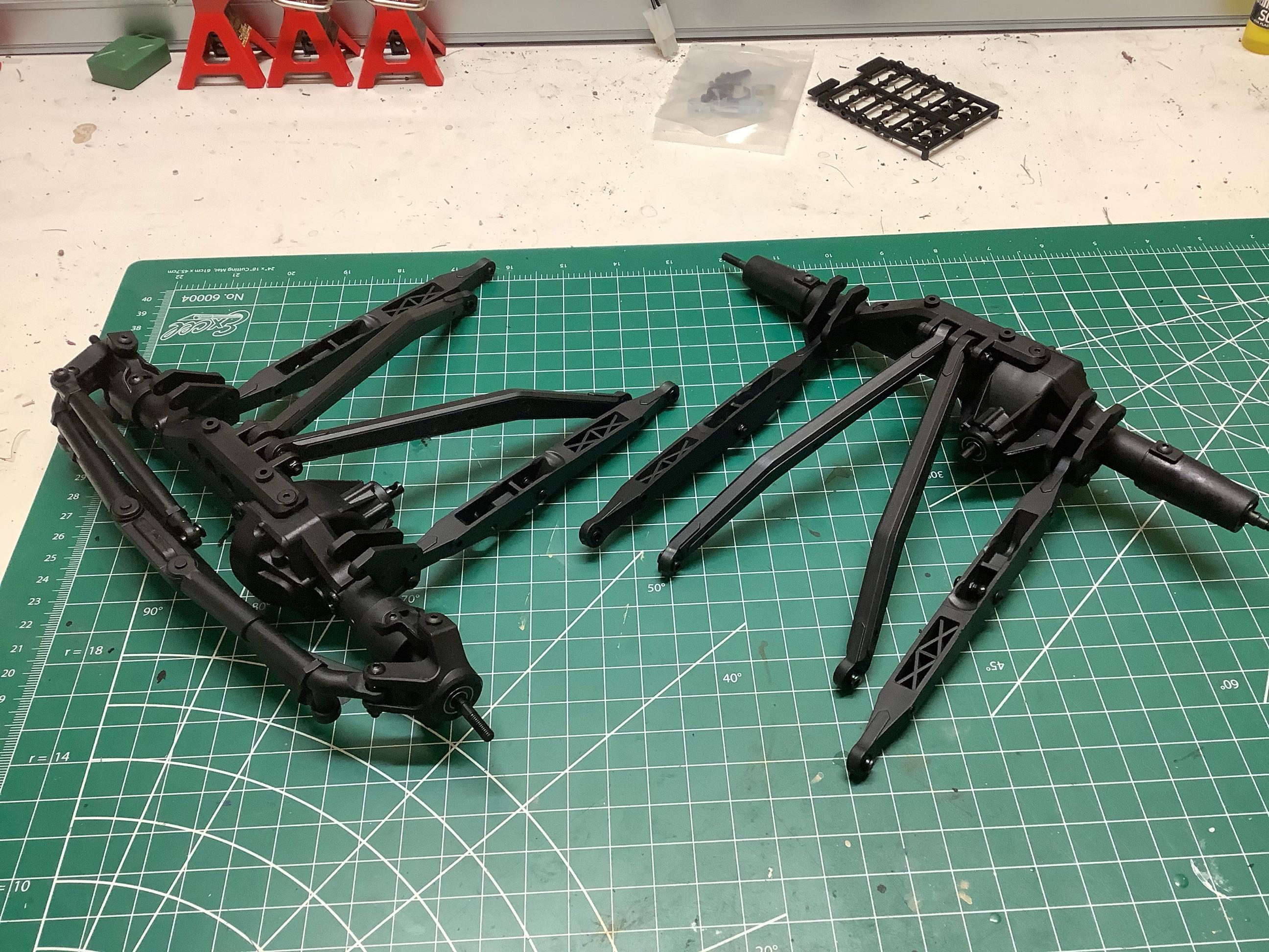
now the trusses and link hangers have been installed as shown on the
left. The same geometry is are used front and rear although the
truss is mirrored. That completes the rear axle, but the front
axle still needs the steering knuckles and links as shown on the
right. The steering tie rod looks very complicated as though it
has integrated shock absorption capability, but it really just a
monolithic plastic part.
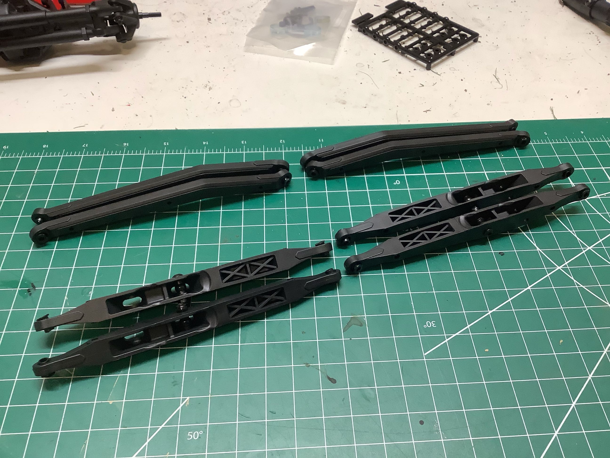
Now the links can be prepared. The lower links are trailing arm
type and will connect to the shocks. These also effectively act as
sliders. The upper links are triangulated and kinked. The
kit only comes with plastic ball joints which I found a bit
disappointing. The right hand picture shows the links, which are
identical front and back, installed on the axles.
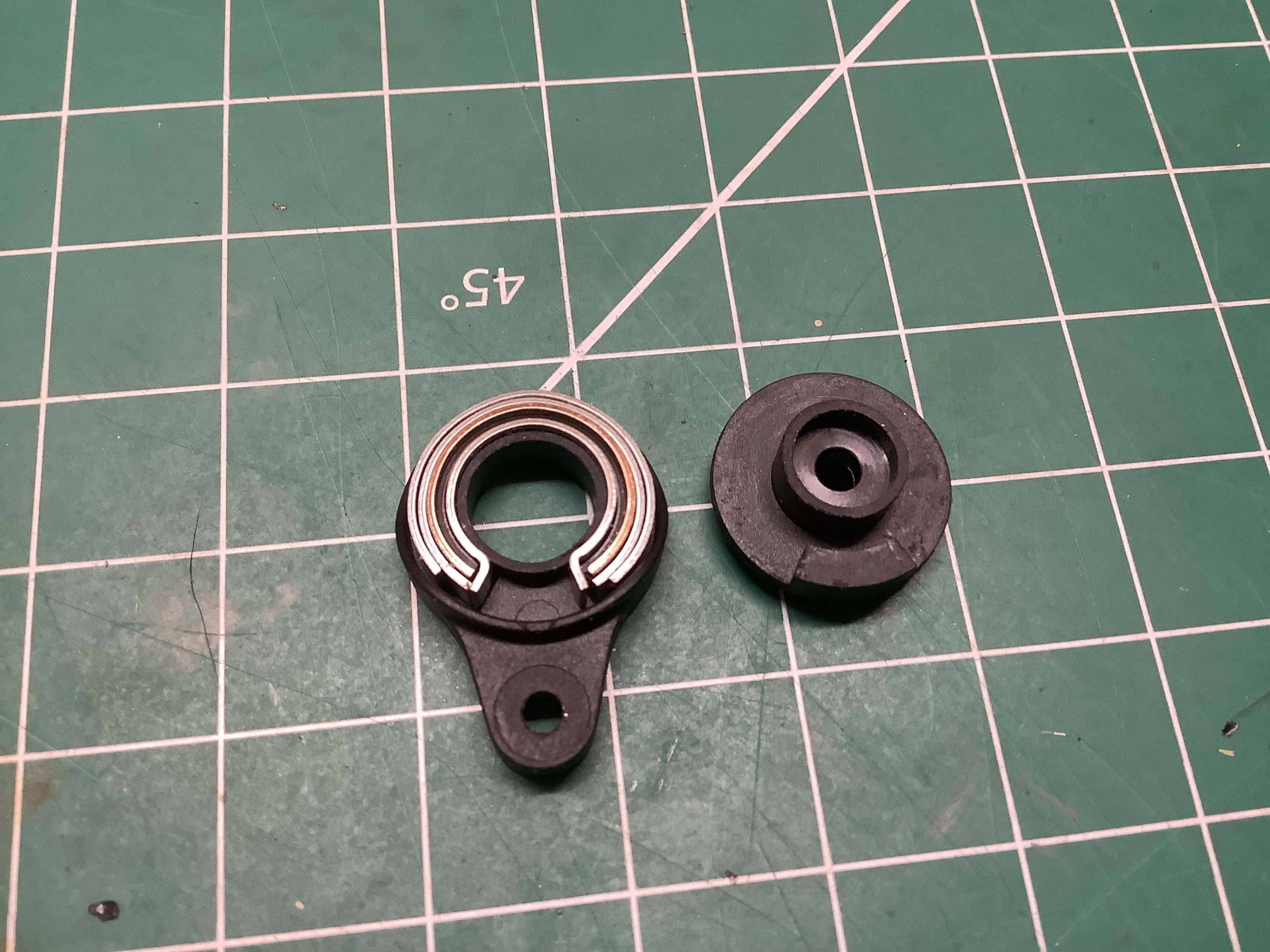
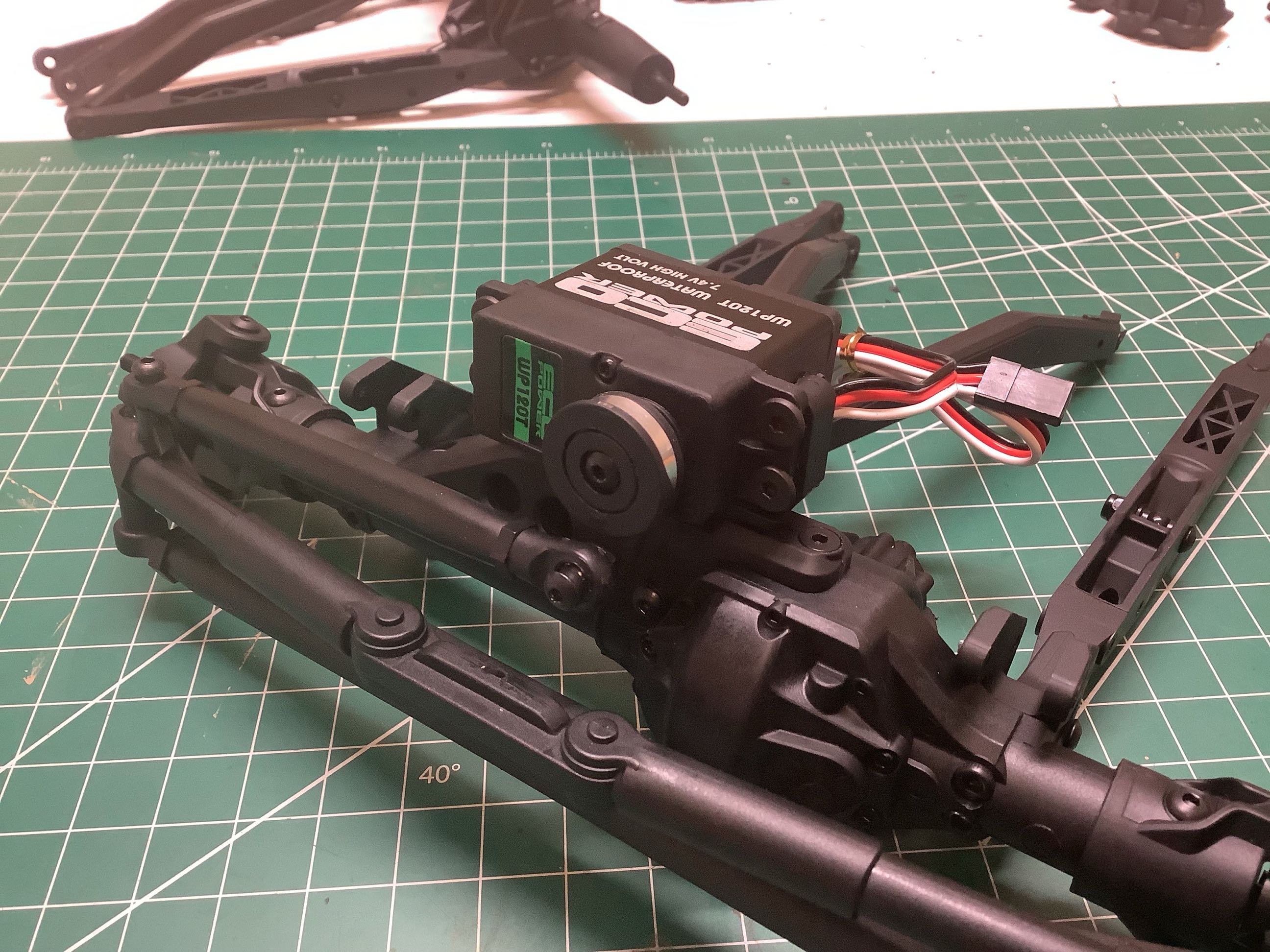
The included servo saver is pretty serious. You can see the 5
levels of steel ring springs shown on the left. On the right I've
mounted the servo to the front axle. This is a temporary servo I
was using until a matching Spektrum servo was back in stock.
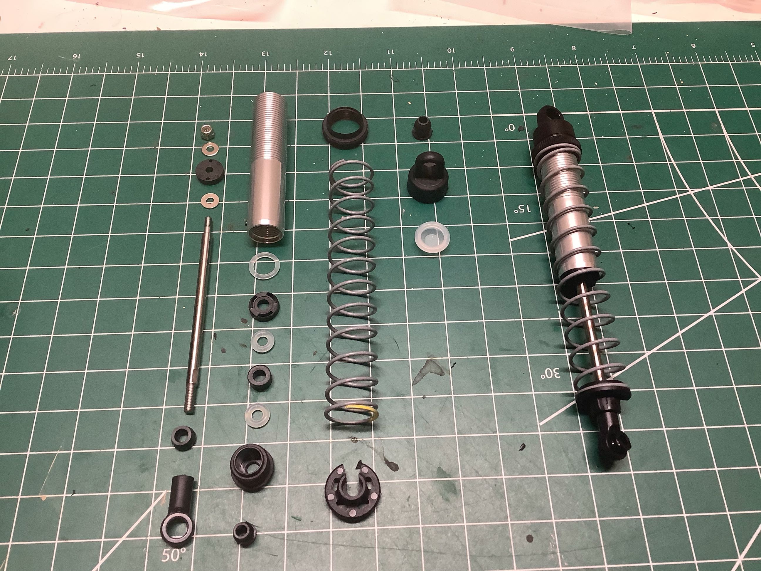
The shocks are very long travel coilover type with aluminum
cylinders. The kit comes with relatively thin 30wt oil. An
exploded view of the shock is shown at left alongside a completed
shock. All four are the same, but front and rear use different
springs. Heavier springs are used in front. On the right you
can see the shocks attached to the trailing arms.
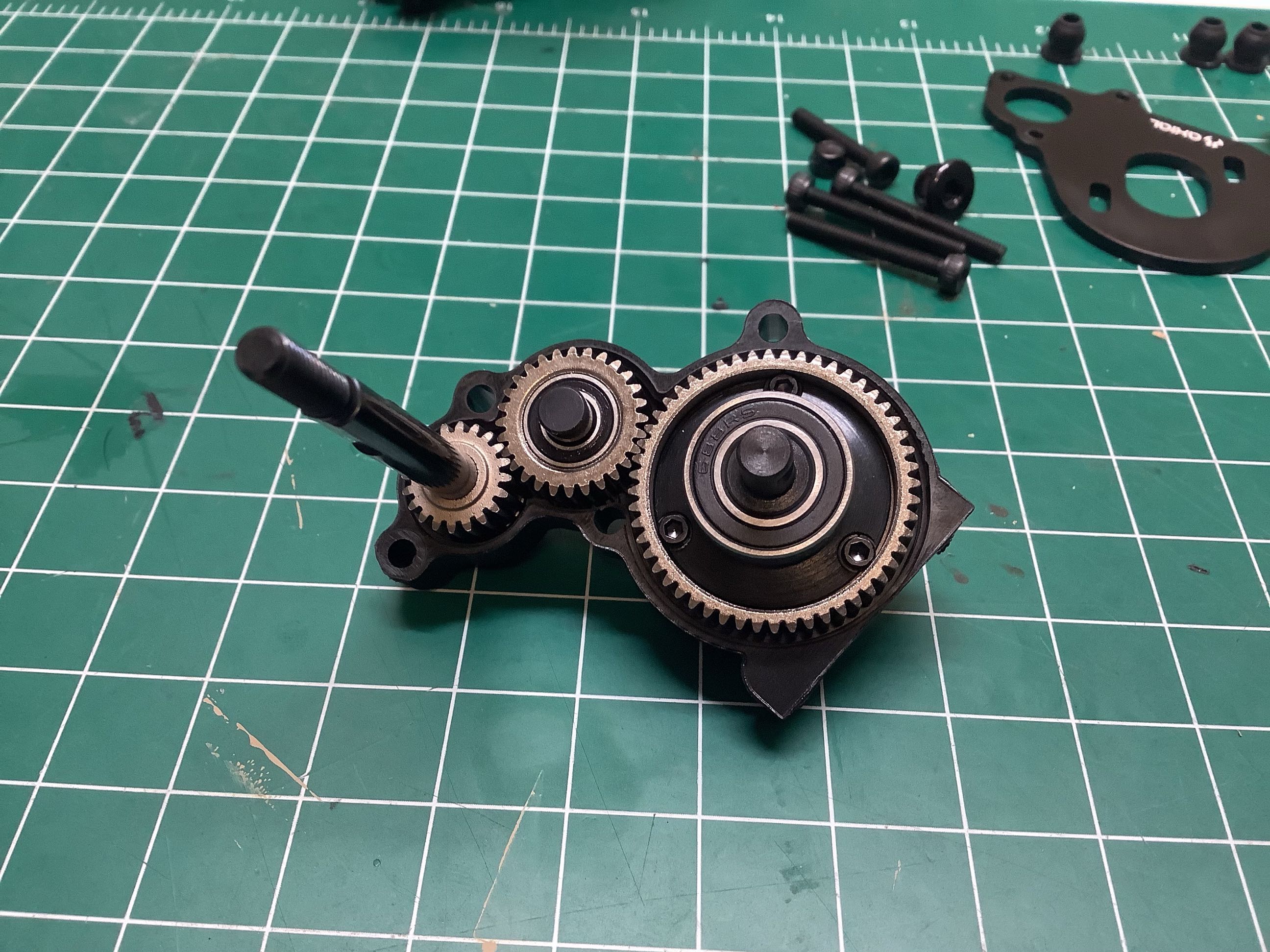
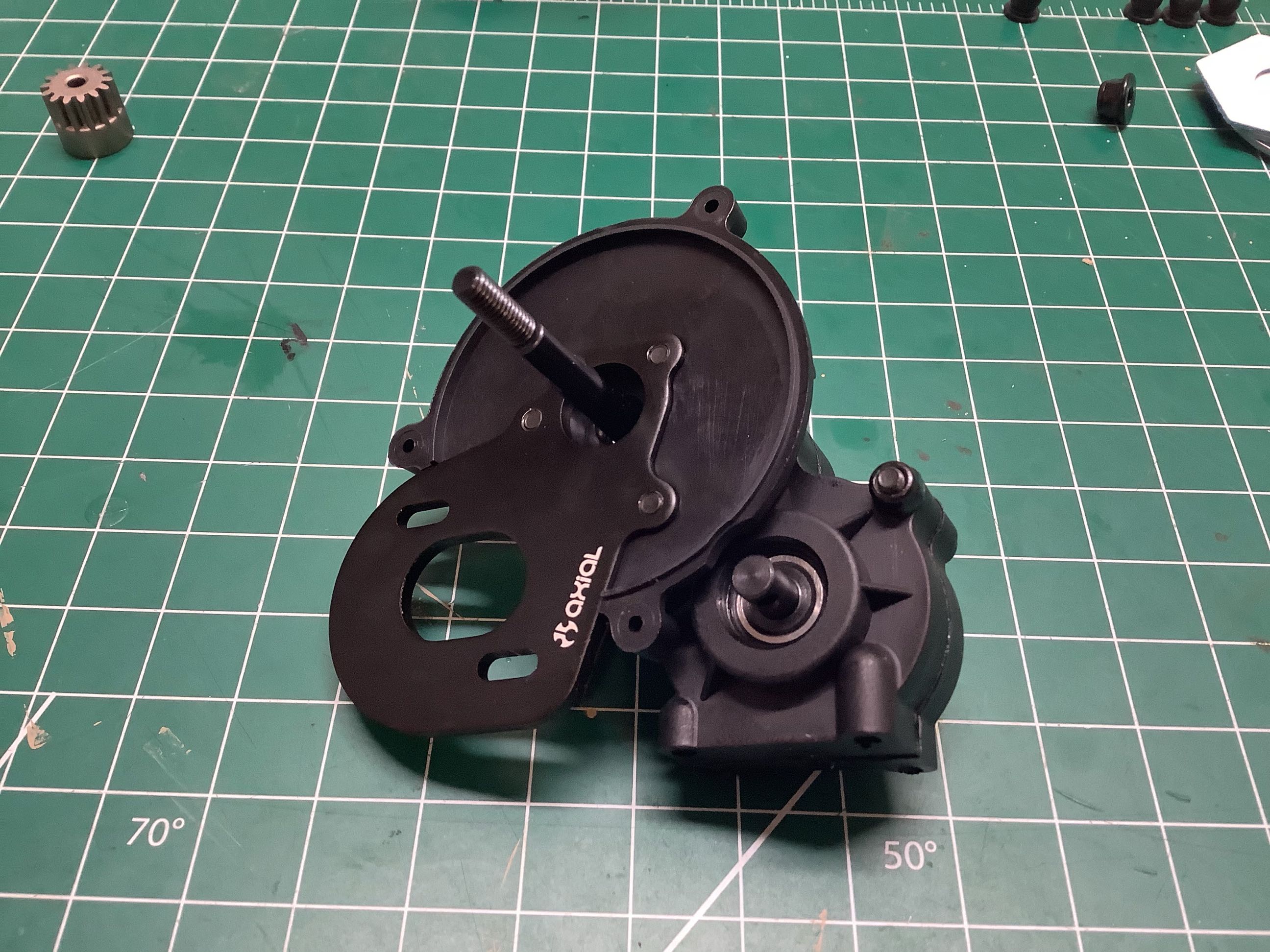
Here is the old reliable Axial AX10 3-gear transmission that has been in
use since the very beginning. The kit comes with nice sintered
metal (not machined) gears and full ball bearings. The left hand
picture shows the guts of the transmission prior to greasing. On
the right I've closed it up and added the metal motor mount.
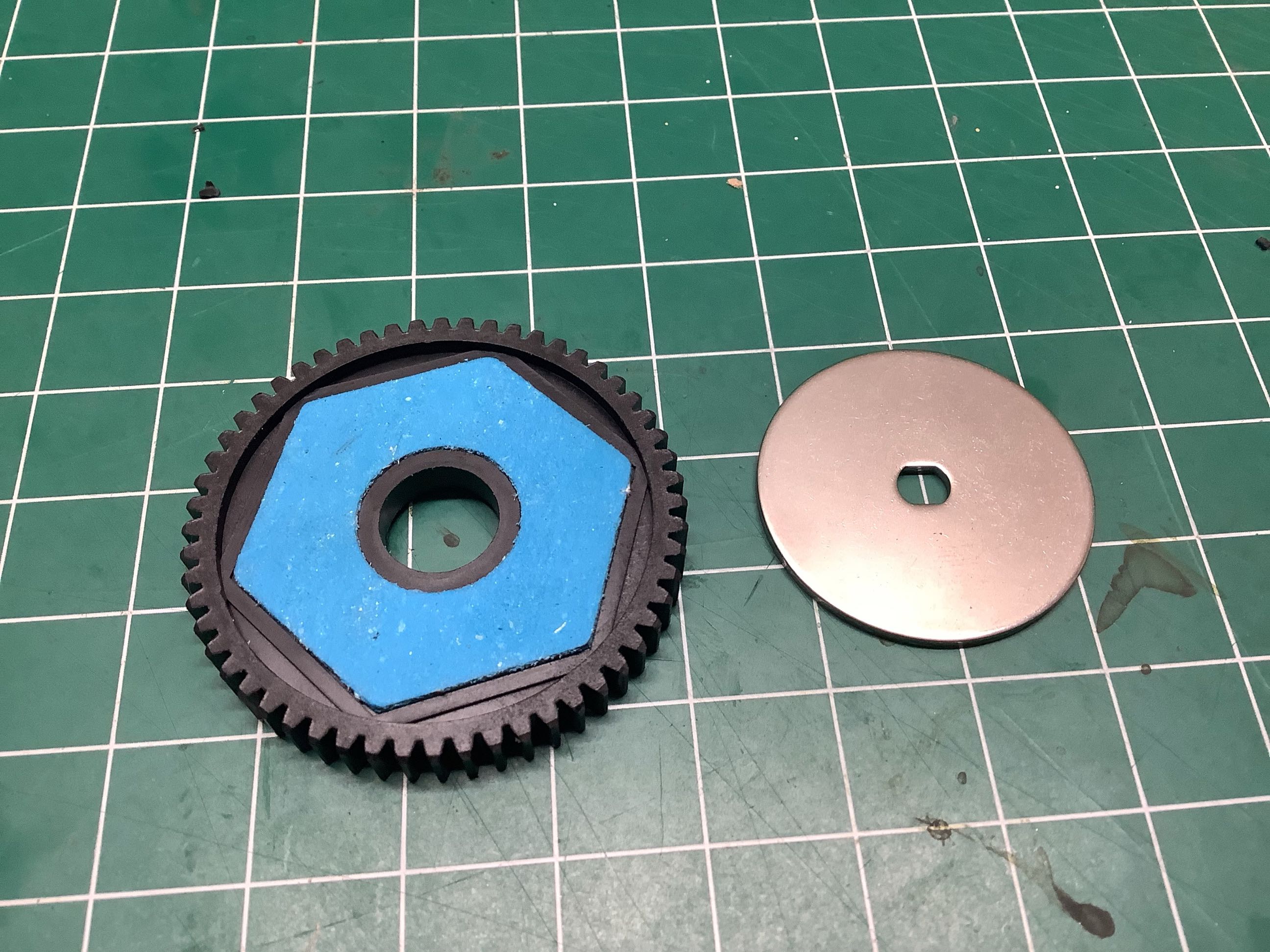
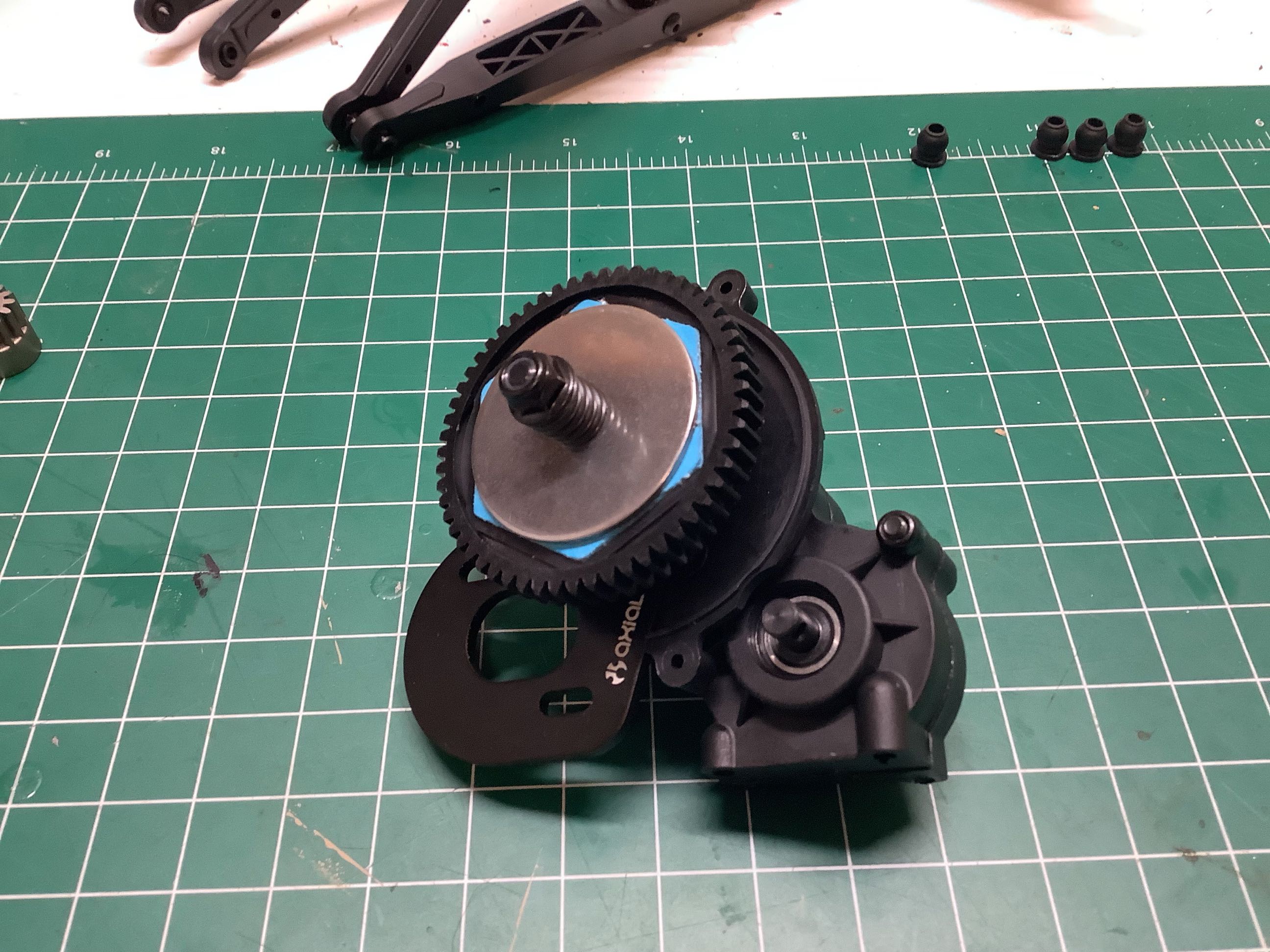
The plastic spur gear uses big 32p teeth and incorporates a slipper
clutch with 2 pads. The compression coil spring shown on the right
clamps the discs against the friction surfaces and regulates the amount
of torque which can pass through the transmission before it slips.
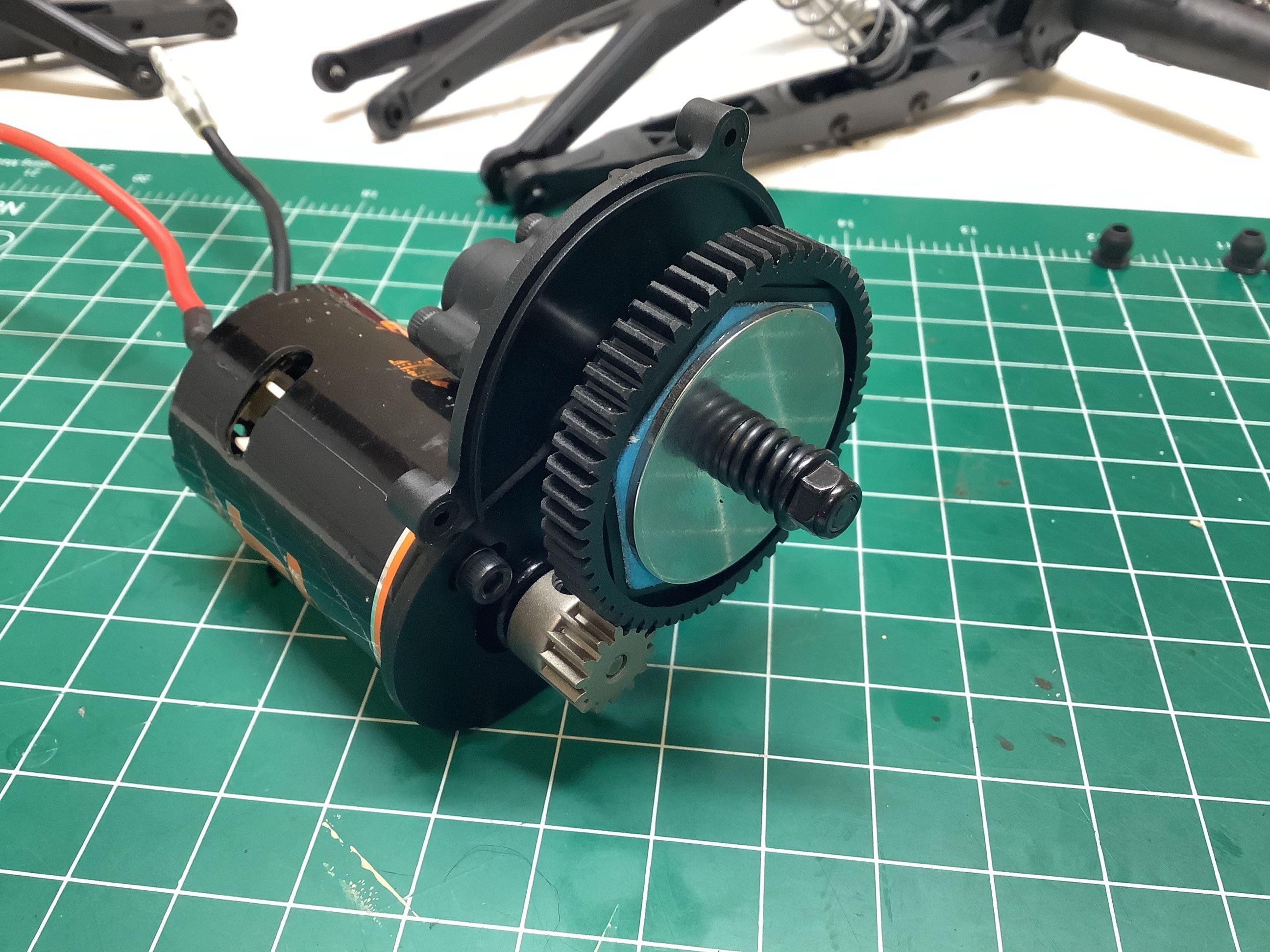
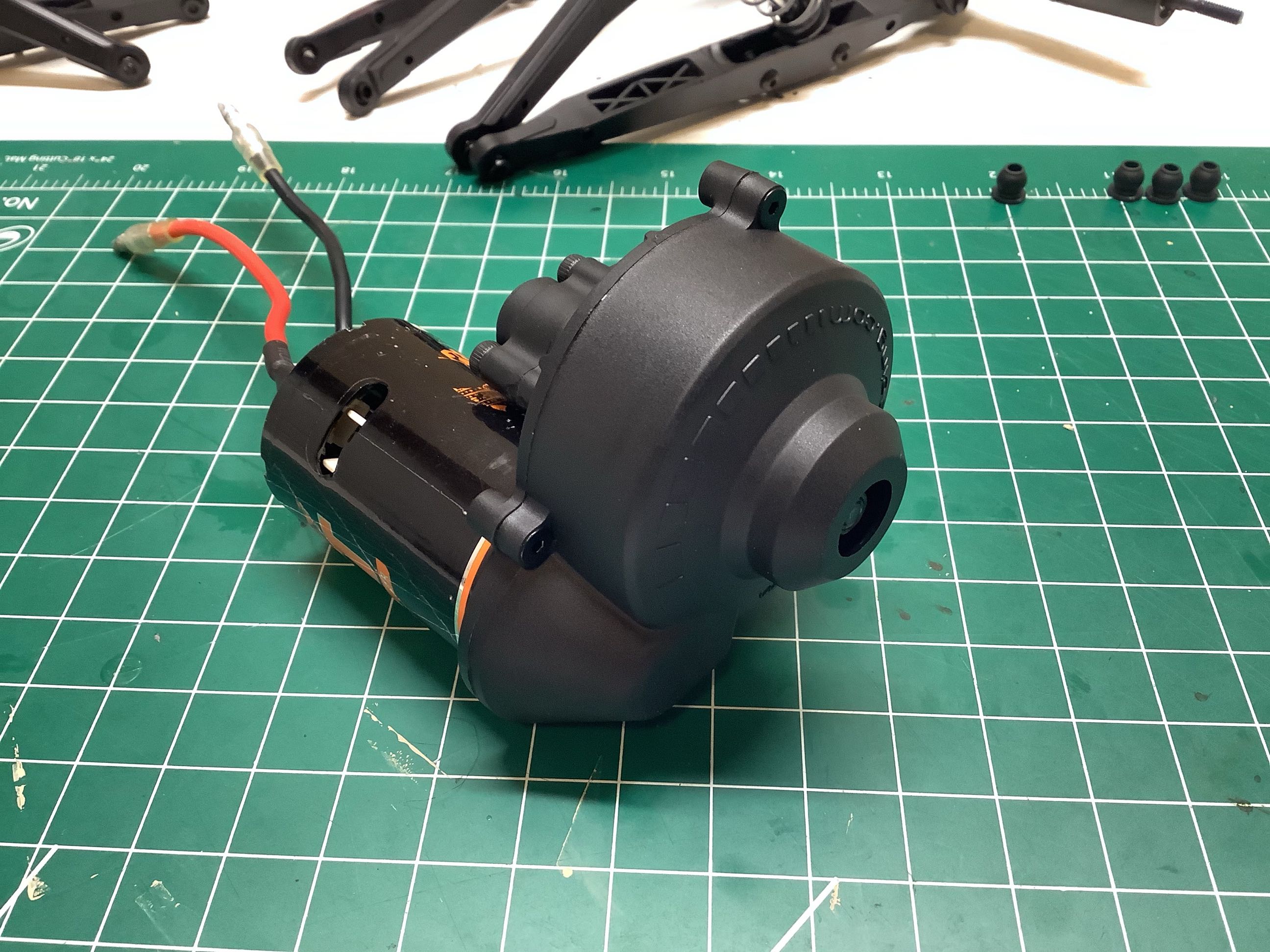
Here I've installed a temporary brushed motor (55T) that I happened to
have lying around. This will certainly not be what I end up using
the vehicle, but it is enough to get started. The kit includes a
14T pinion gear and a 56T spur. On the right I've attached the
gear cover. Note the central opening which allows access for
adjusting the slipper.
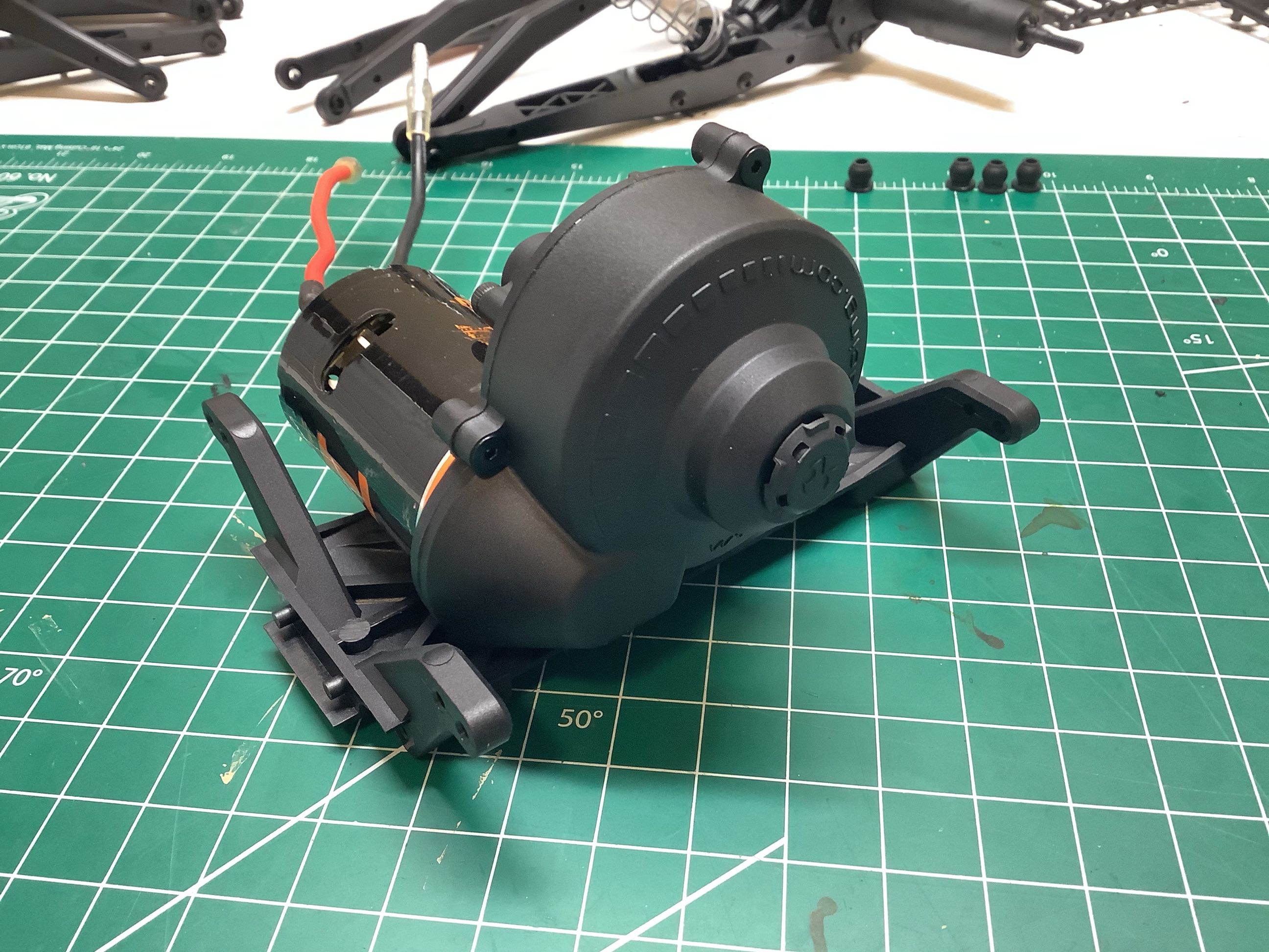
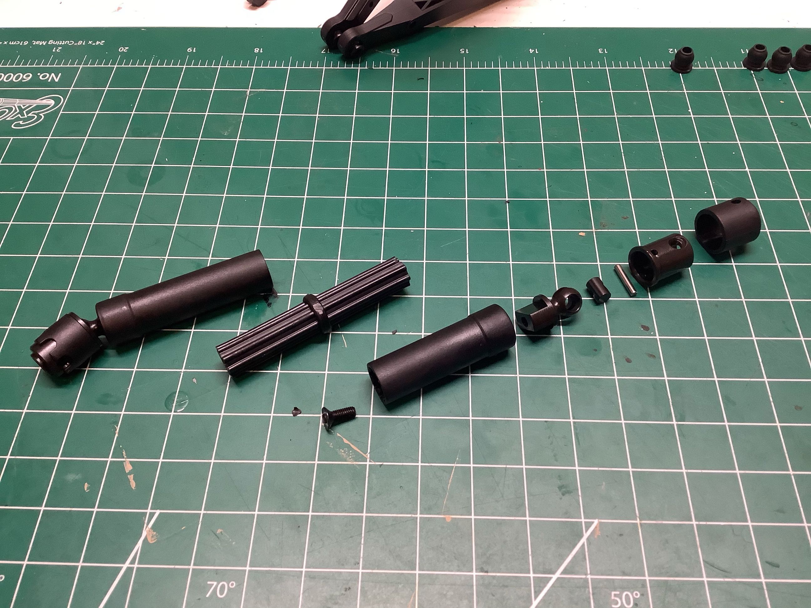
Now I've bolted the transmission to the skid plate as shown. On
the right I've started assembly of the drive shafts which are made up of
quite a few parts. The far right is an exploded view. These
are Axial's standard shafts which, despite being plastic, hold up very
well. The highly stressed end joints are steel. Only the
sliding splined shafts are plastic.
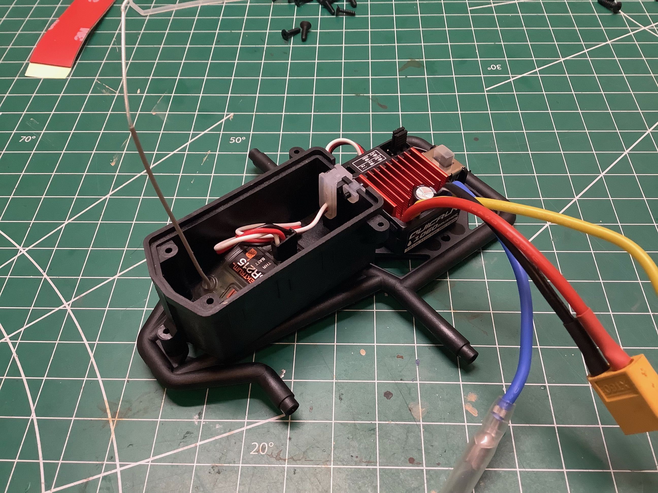
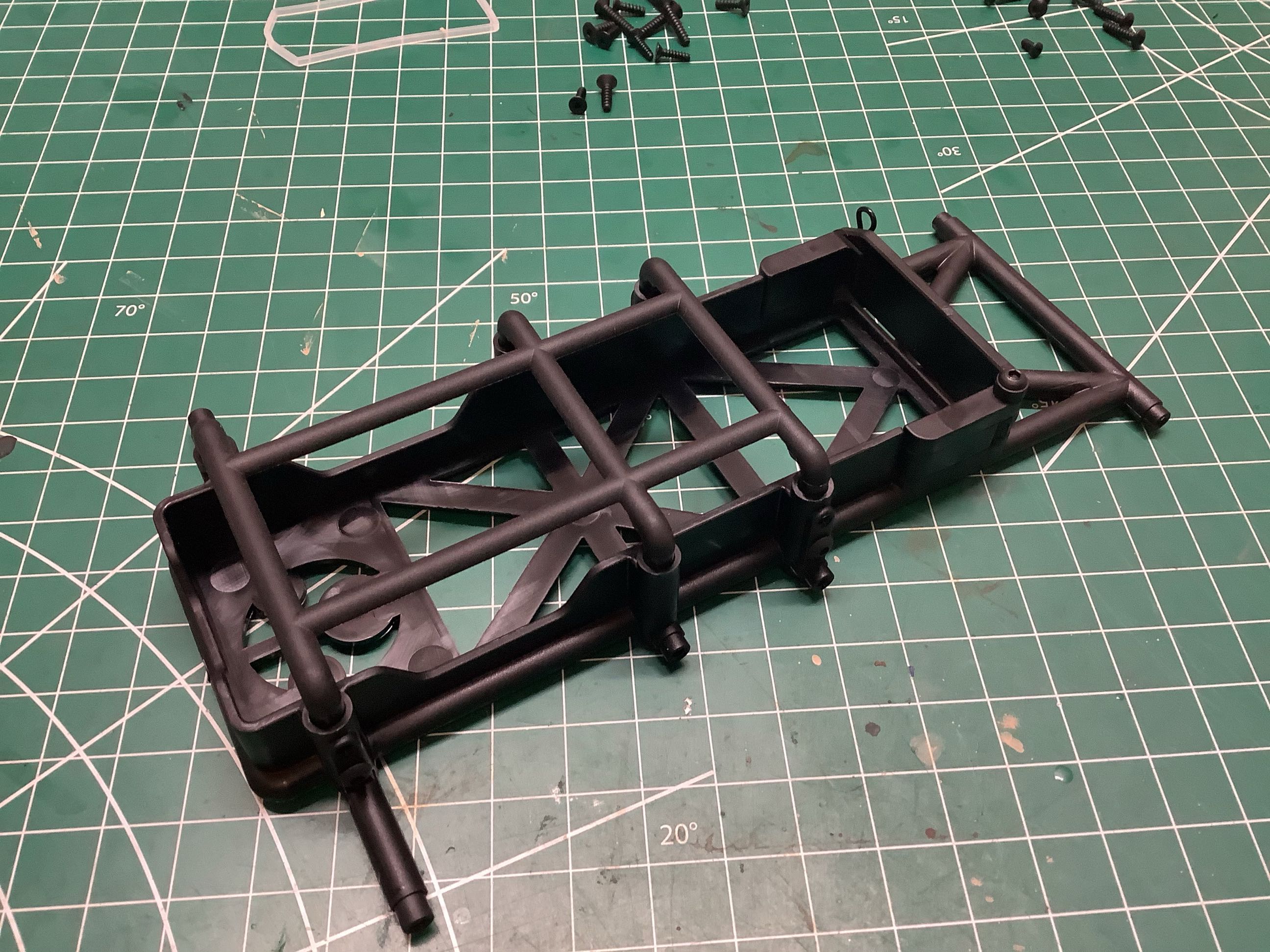
Th receiver box in attached to a cross member as shown. The box is
quite spacious and more than enough for my Spektrum 2-channel
receiver. A temporary brushed ESC is also shown installed.
The right hand picture shows the battery box. The upper cage part
is adjustable up and down for batteries of different thicknesses.
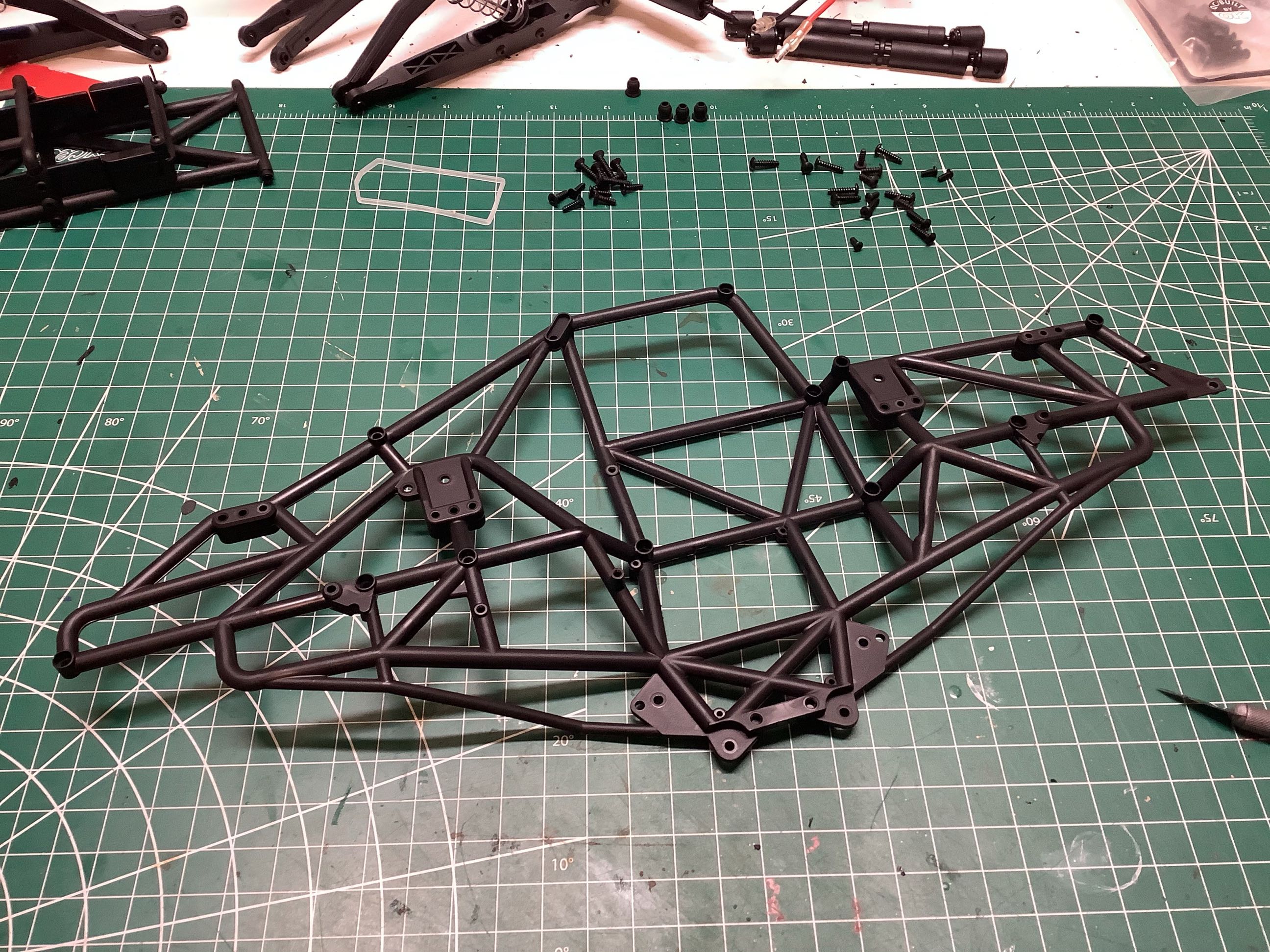
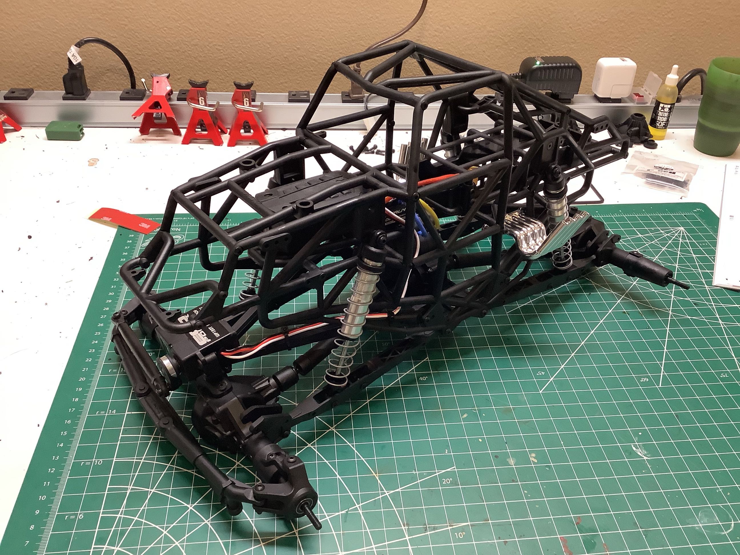
Now we get to the major structural parts, the chassis cage halves.
The first one-piece half is shown on the left. Although I would
have preferred to build this up out of many pieces, the monolithic
design is stronger and cheaper. On the right I've added all the
various cross members which will join the two halves.
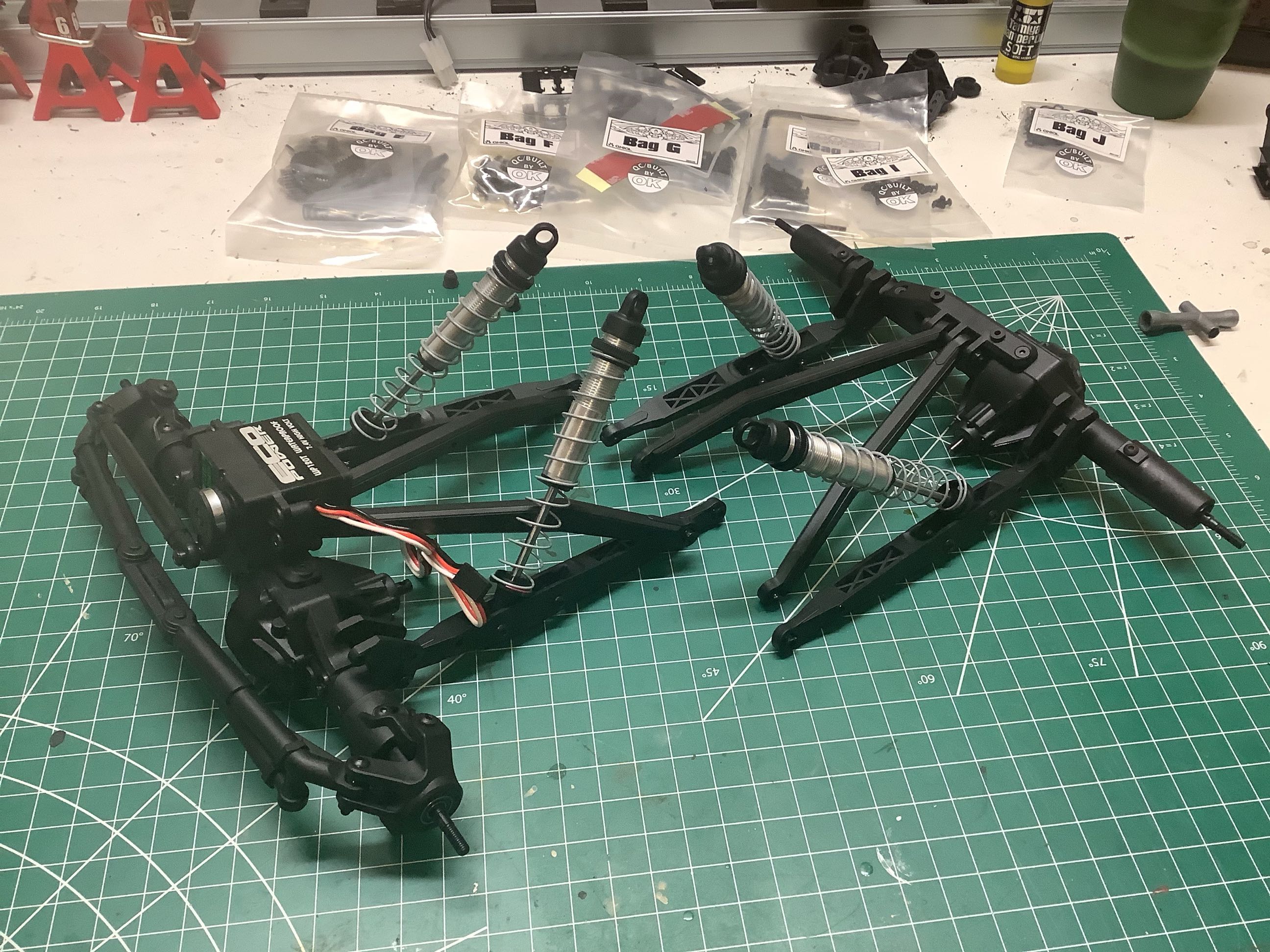
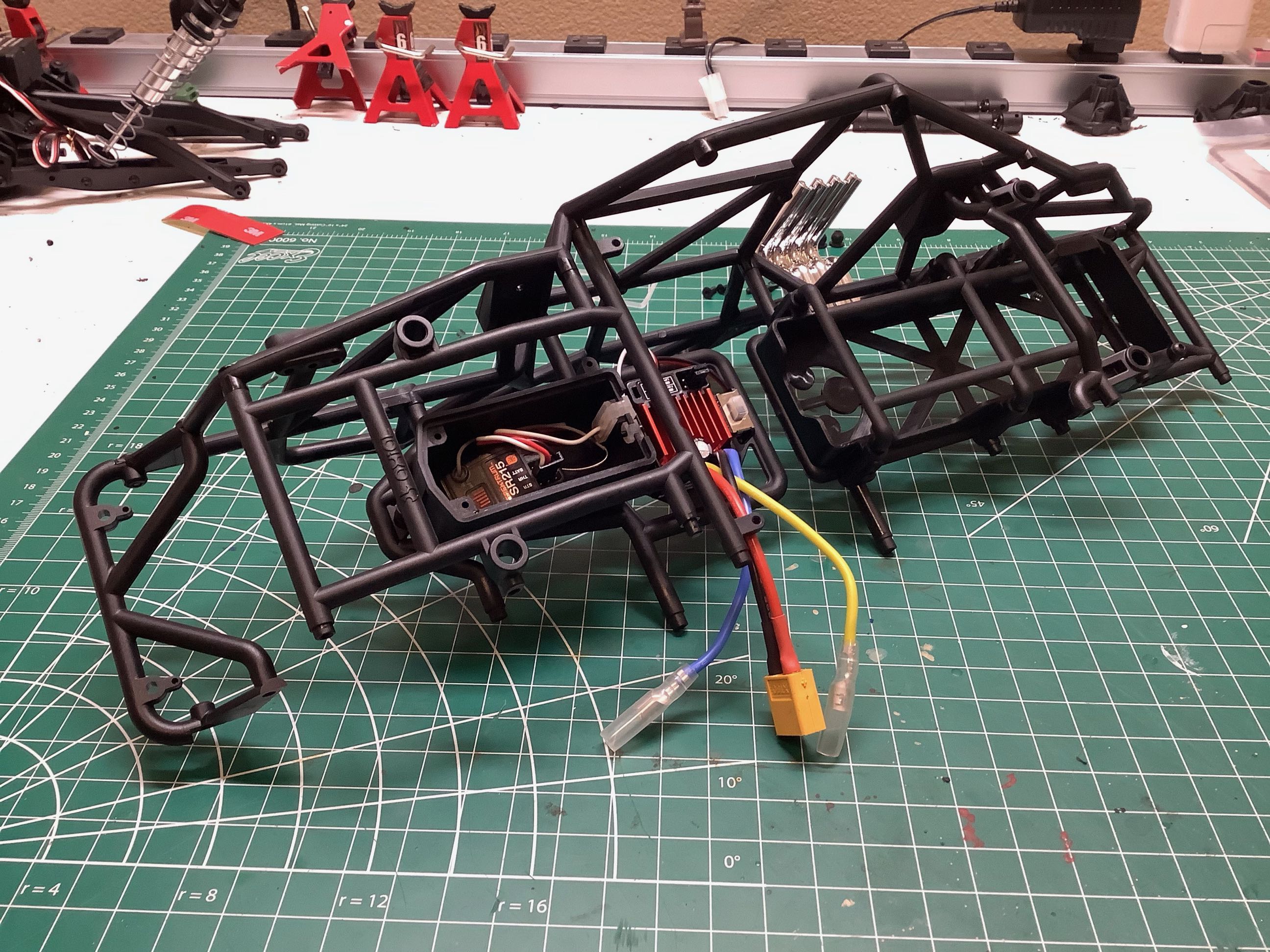
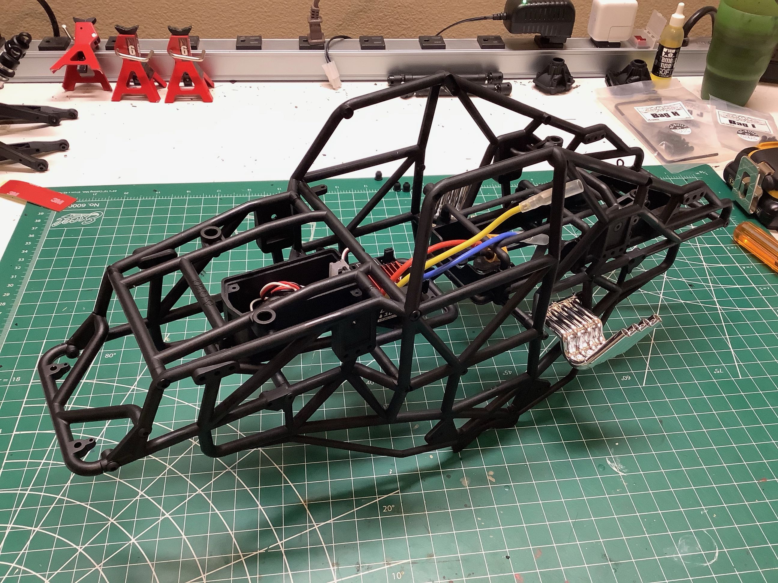
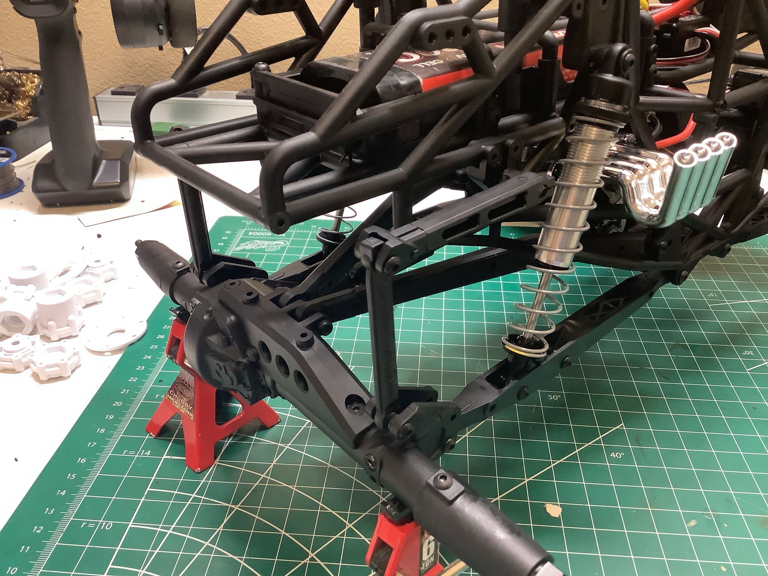
Here is the second cage half has been secured in place completing the
chassis. On the right I've attached the links and shocks to the
chassis cage which is all that is needed to make this a usable rolling
chassis.
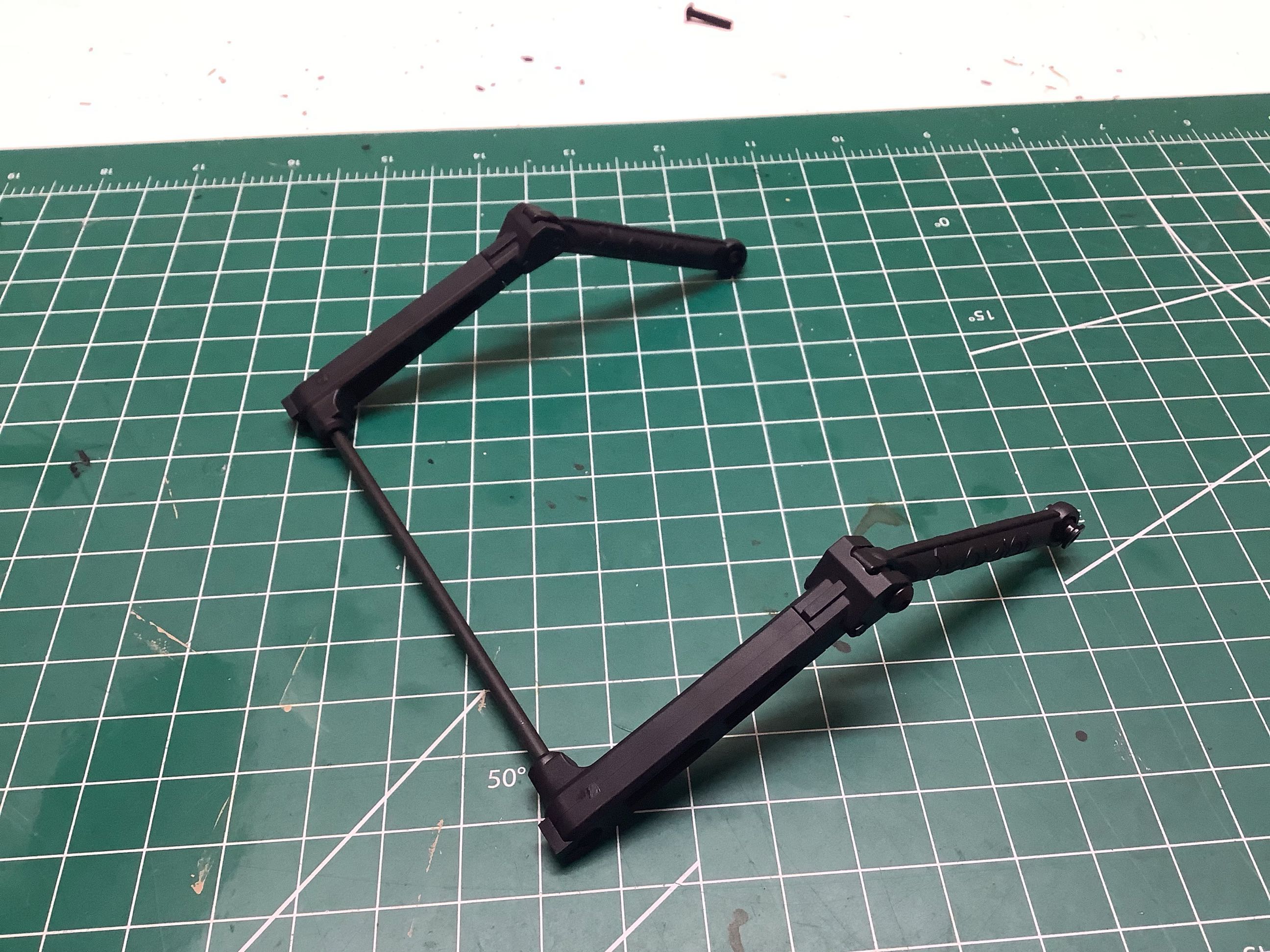
The kits comes with a sway bar for the rear only as shown. This is
intended to reduce body roll but I still had major issues as has been
discussed elsewhere. I ended up adding a second sway bar to the
front and greatly stiffening the shock springs.
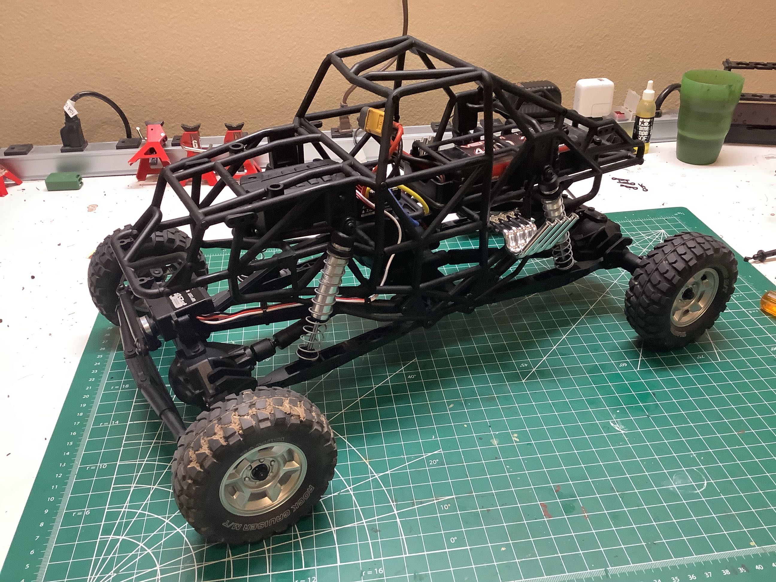
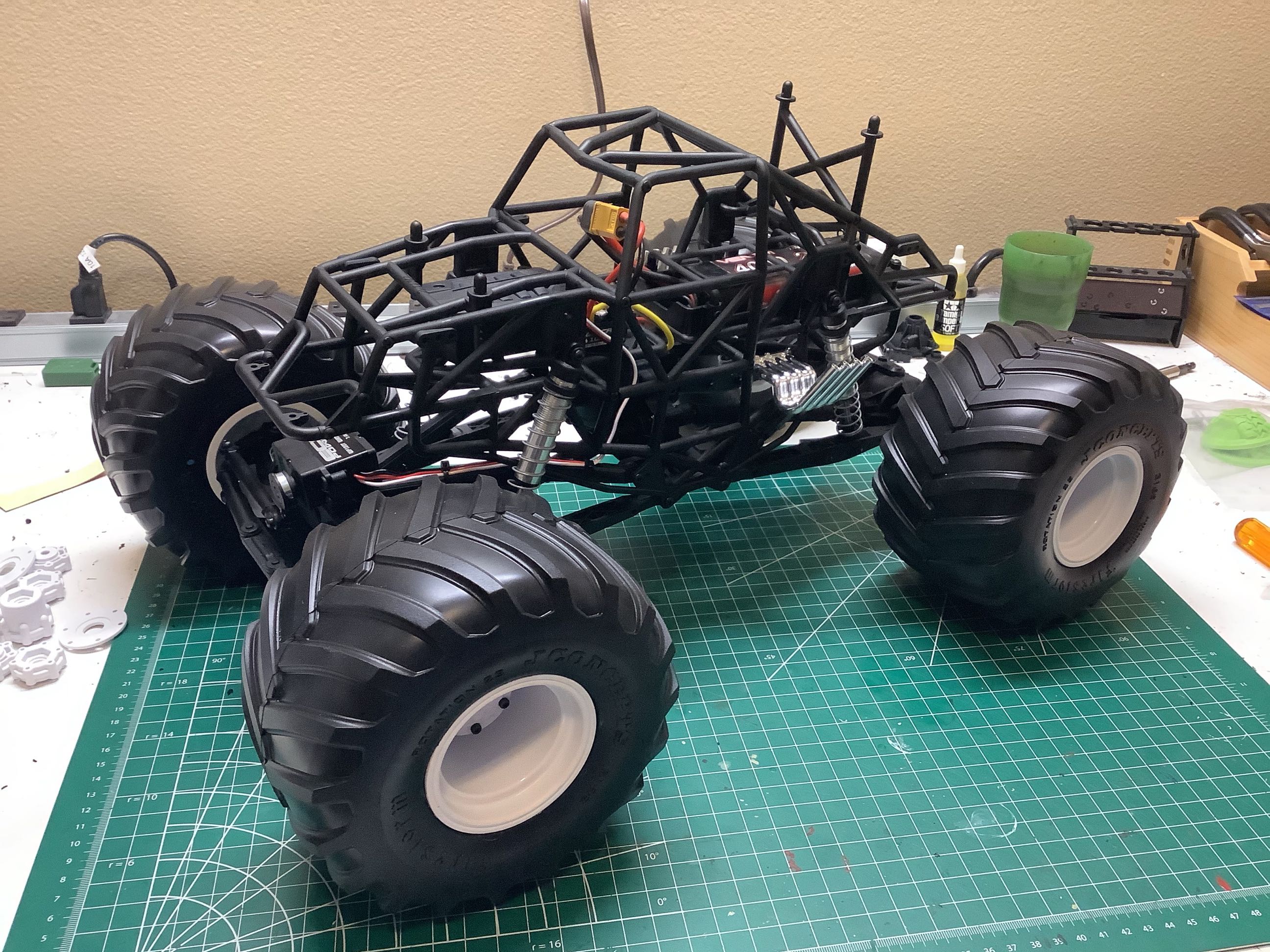
Here I've added some test tires just to try out the chassis. As
ridiculous as it looks, real monster trucks are trailered with tiny
tires like these to keep them low enough to pass under bridges.
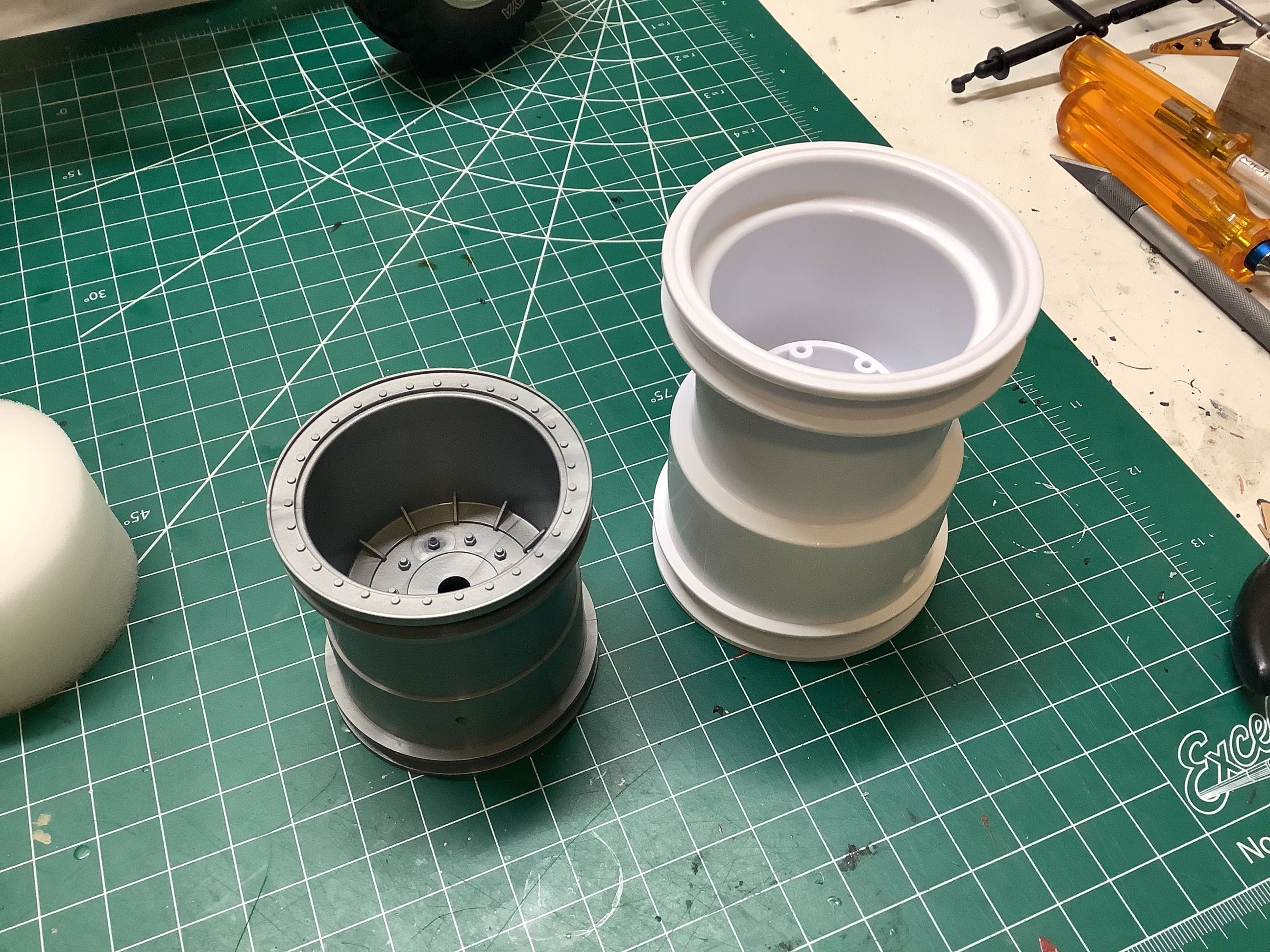
The picture on the left compares the large silver wheels which came with
the kit to the much larger white wheels from JConcepts I decided to use
instead. This choice had quite a few consequences on handling
since this chassis was really made for the smaller tires with lower
power. That means a lot of other modifications were in my future.
©2021 Eric Albrecht