Tamiya Sand Scorcher Project

Page 1:  Assembly


The Sand Scorcher comes in a really large box.  This is partly because of the large hard body, but also due to the very careful packaging and presentation.  Just take a look at the contents!  There is a blister pack on either side of the body that really shows off the majority of the metal components.  Underneath are the hardware bags, the plastic trees, and the instructions.  This box is so nice I will probably save the cover and hang it on the wall later.


Here are all the parts laid out on my building table.  The first thing I notice is how few plastic parts there are.  Typically a kit would be packed with a dozen or so plastic parts trees, but not this kit.  Almost everything is metal.  The few things that are not I'll probably be replacing with metal later.  The build starts with the gearbox.  You can see that the upper gear is brass but the lower two are nylon.  The lowest of the gears takes the place of a differential but is just a solid spool.  At least we don't have to worry about any fragile bevel gears breaking.  You can't see it from this angle, but the axle for the top gear protrudes out the back of the gearbox and will hold the spur gear later.  The kit includes full ball bearings throughout. 


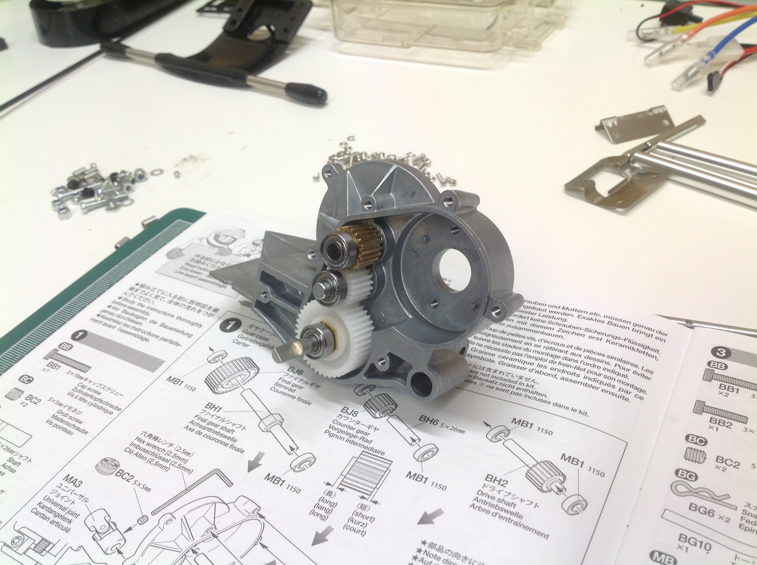
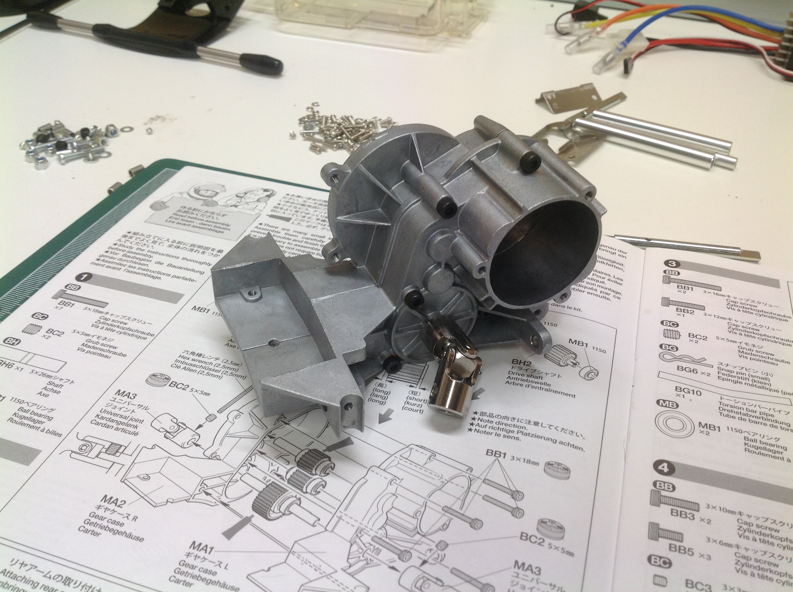
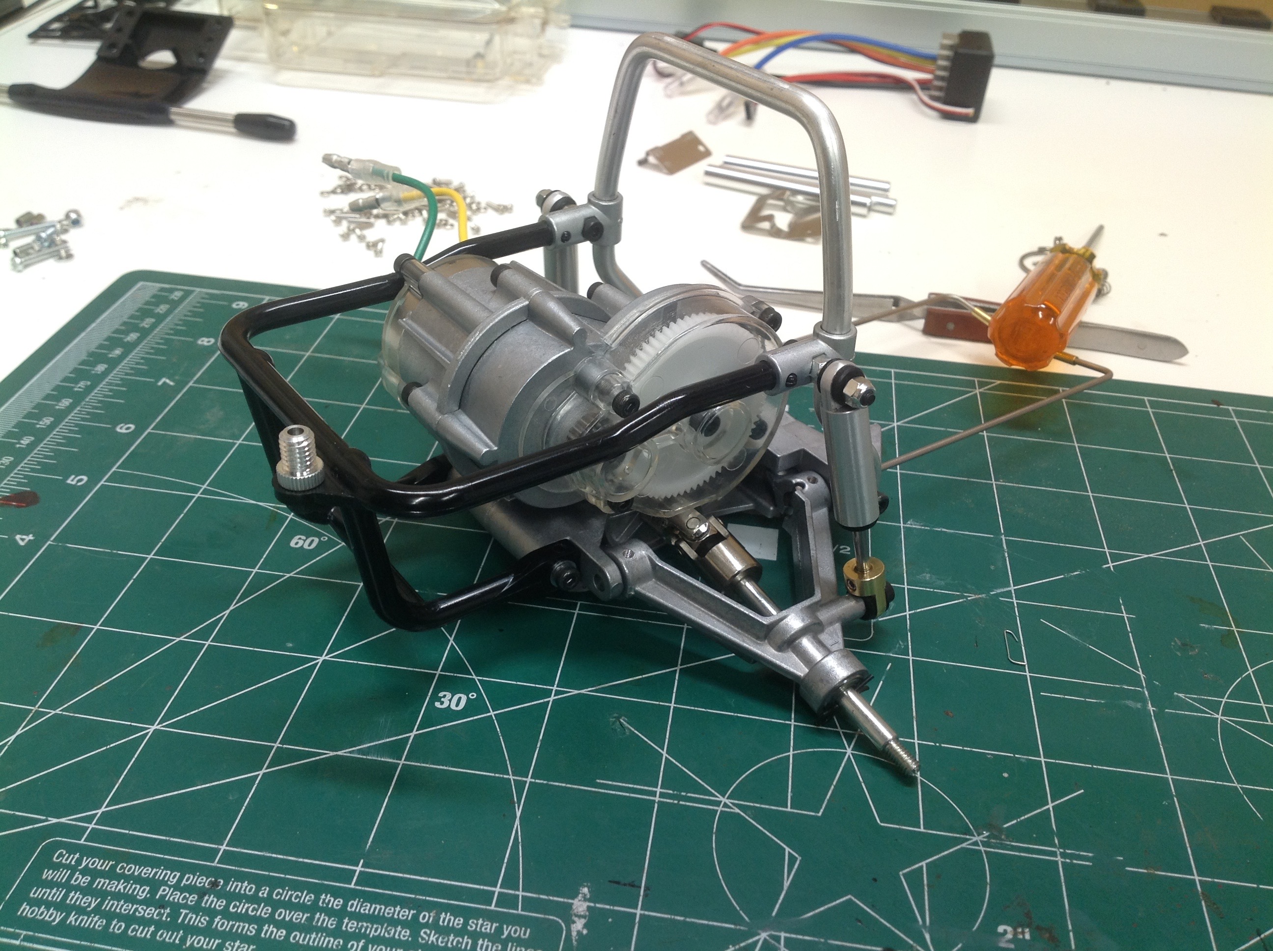
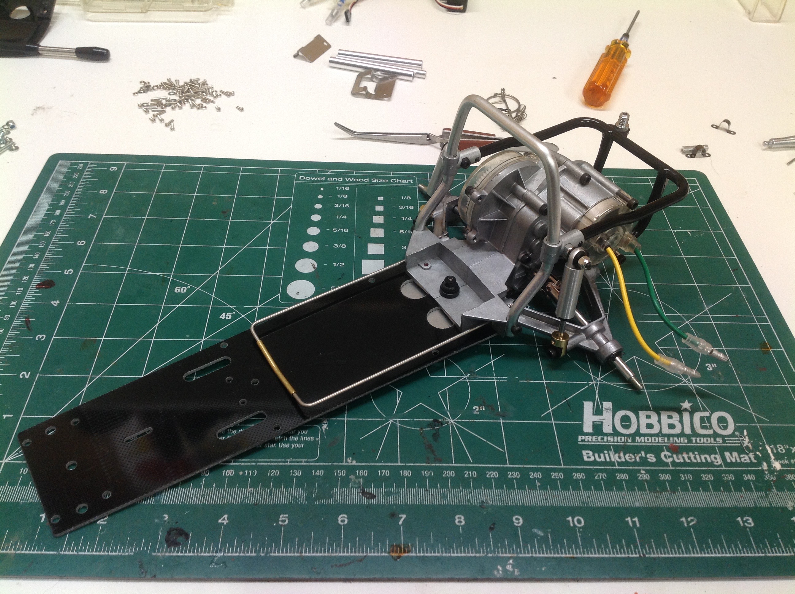
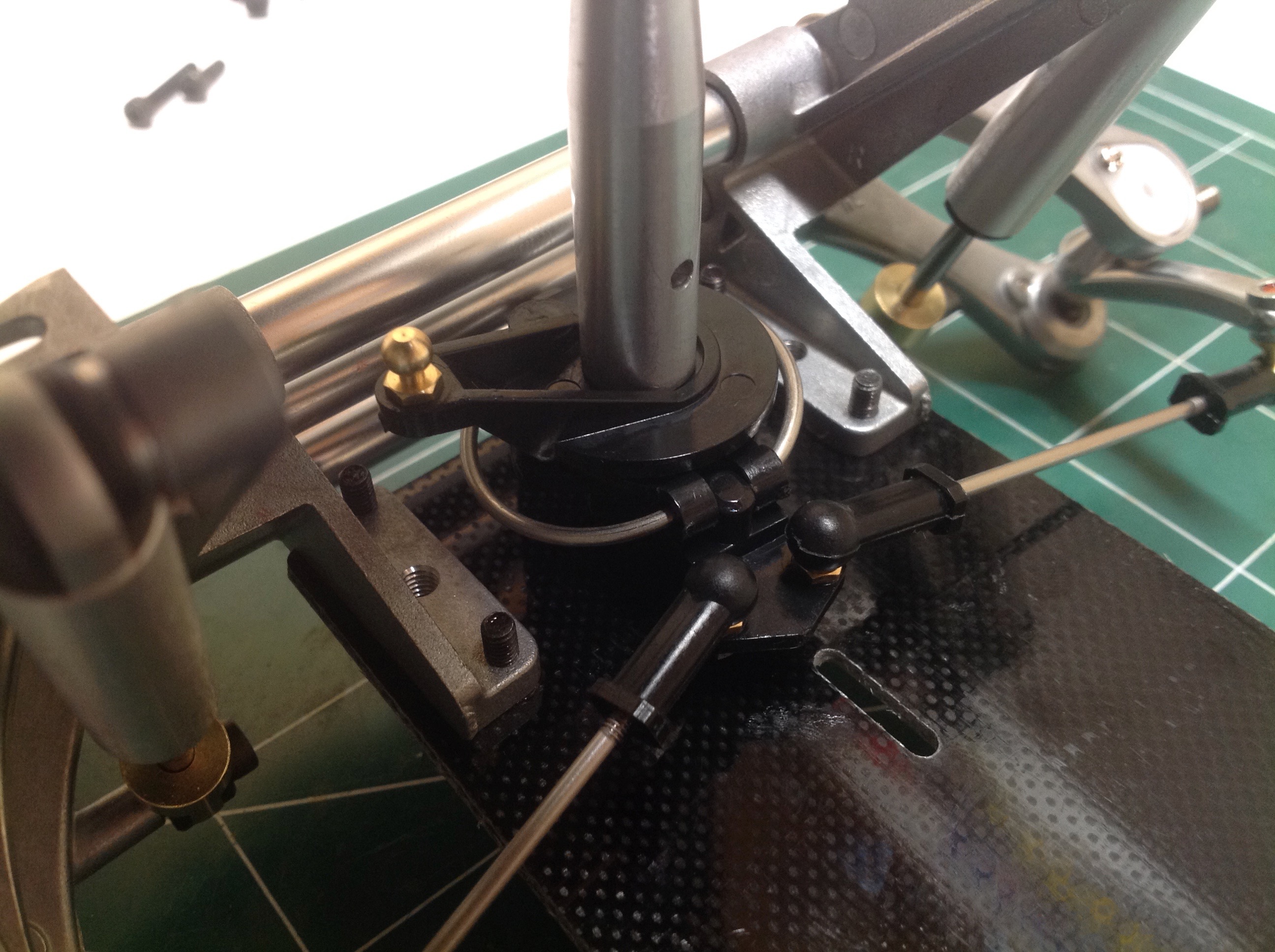
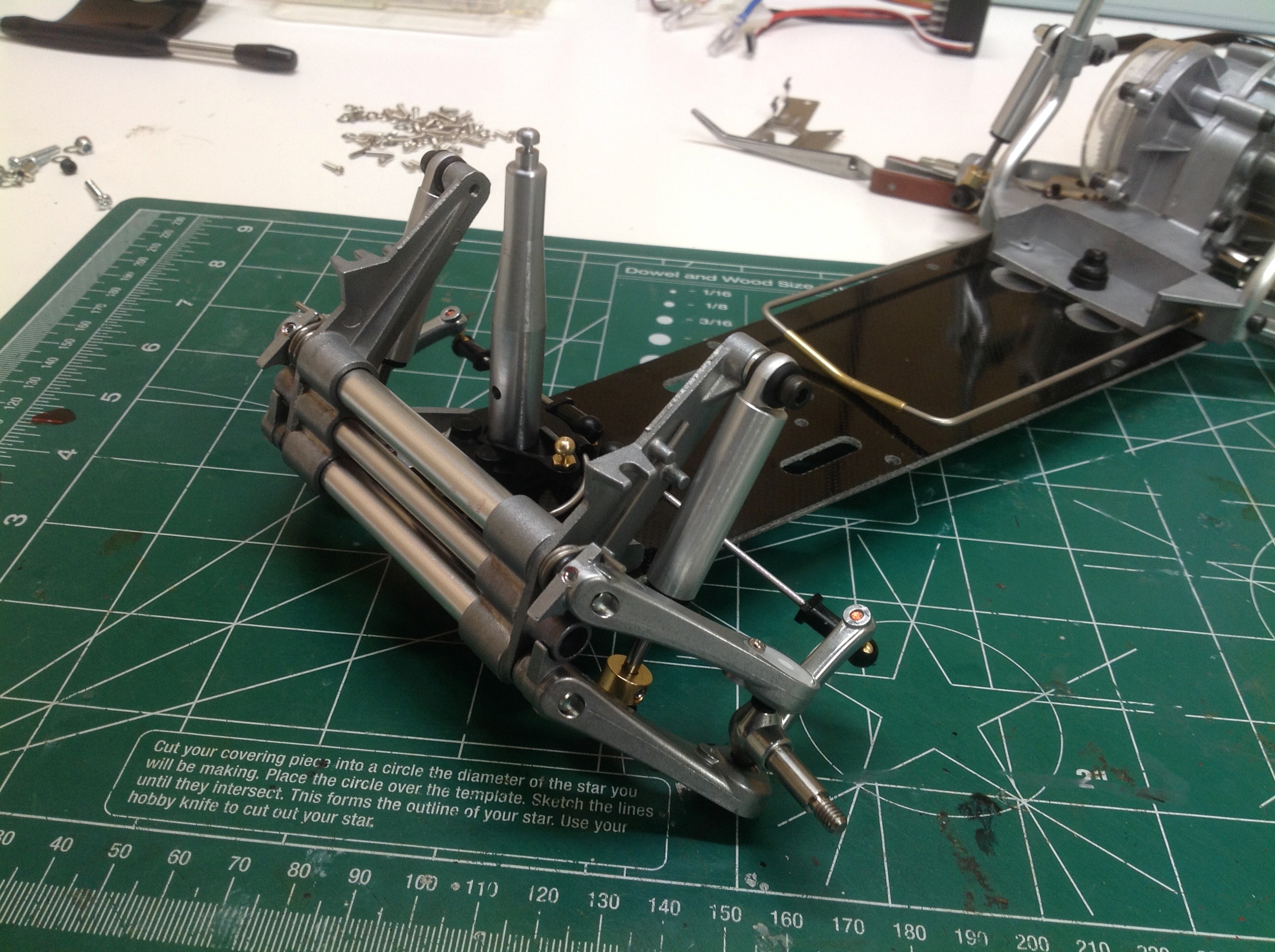
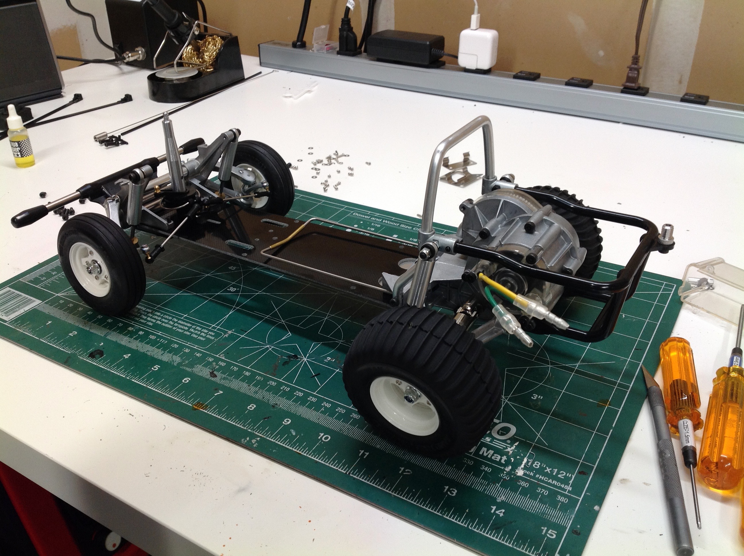
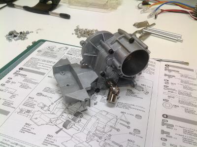
This shows the gearbox closed up with the universal 
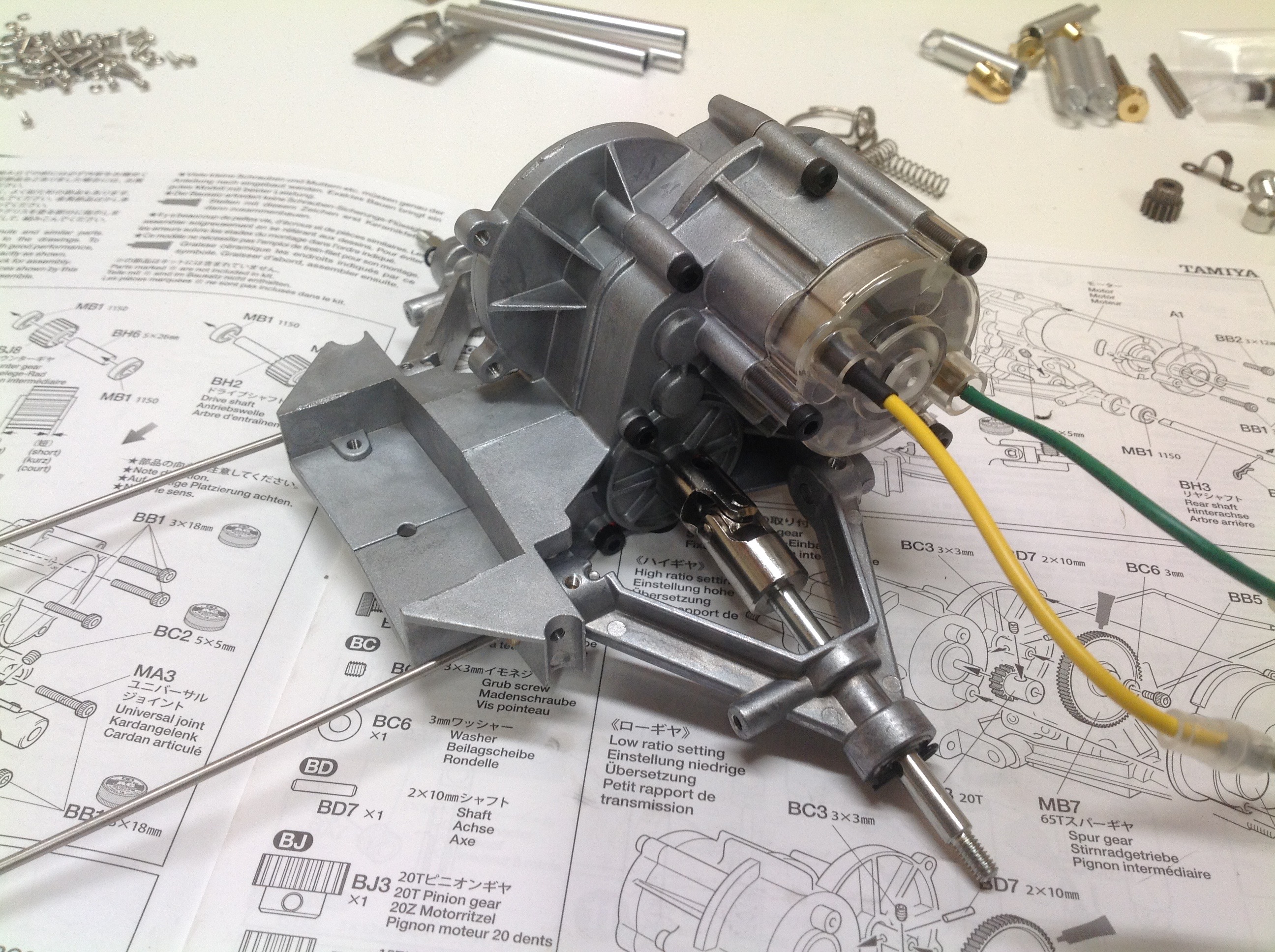
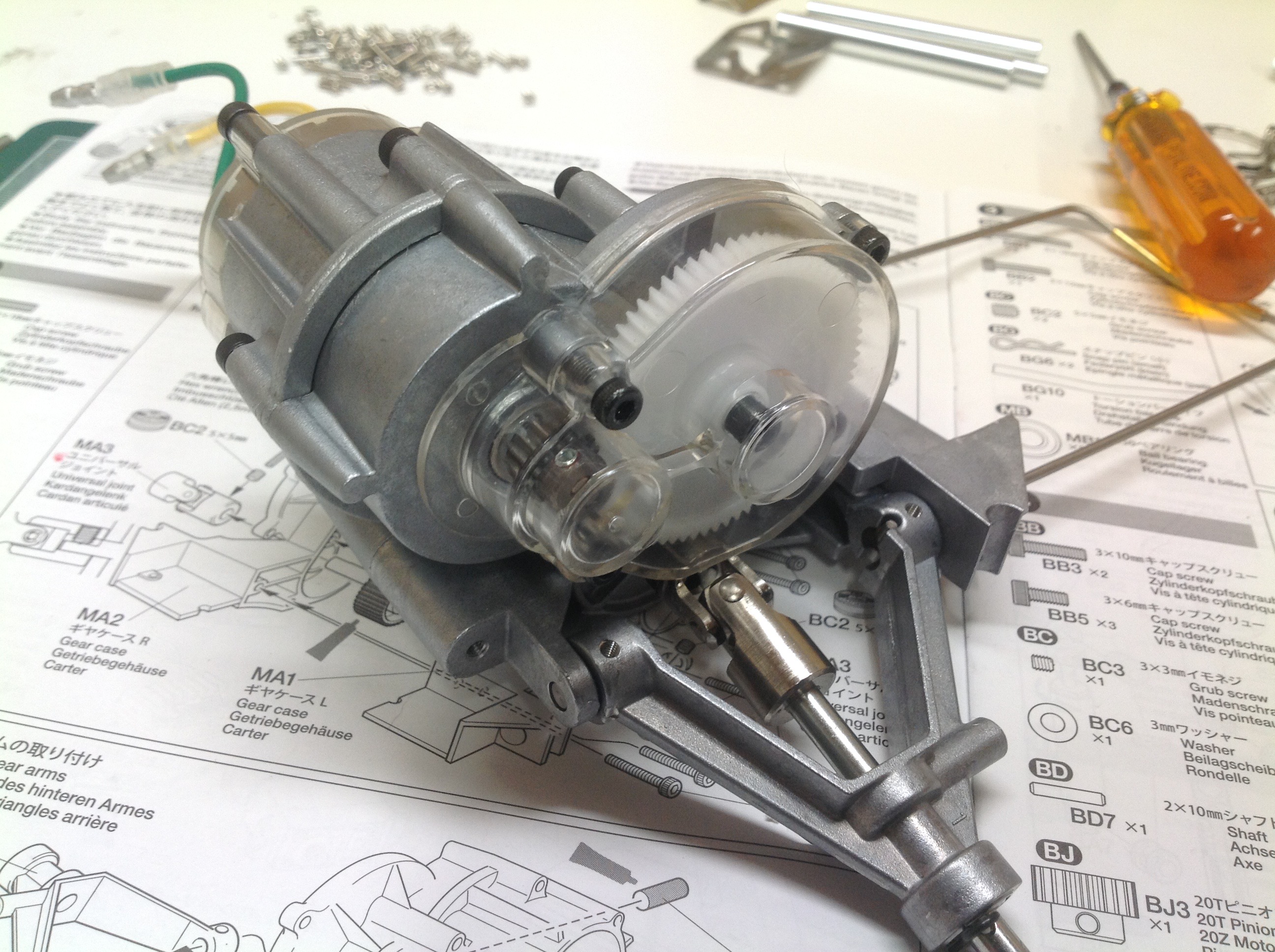
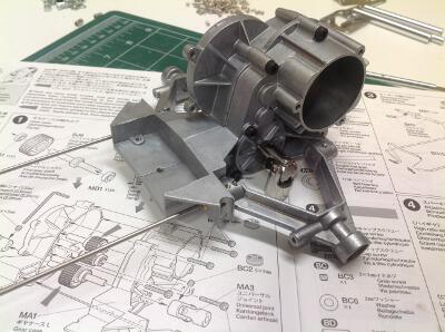
joint outdrives attached.  In the right hand image I've attached 
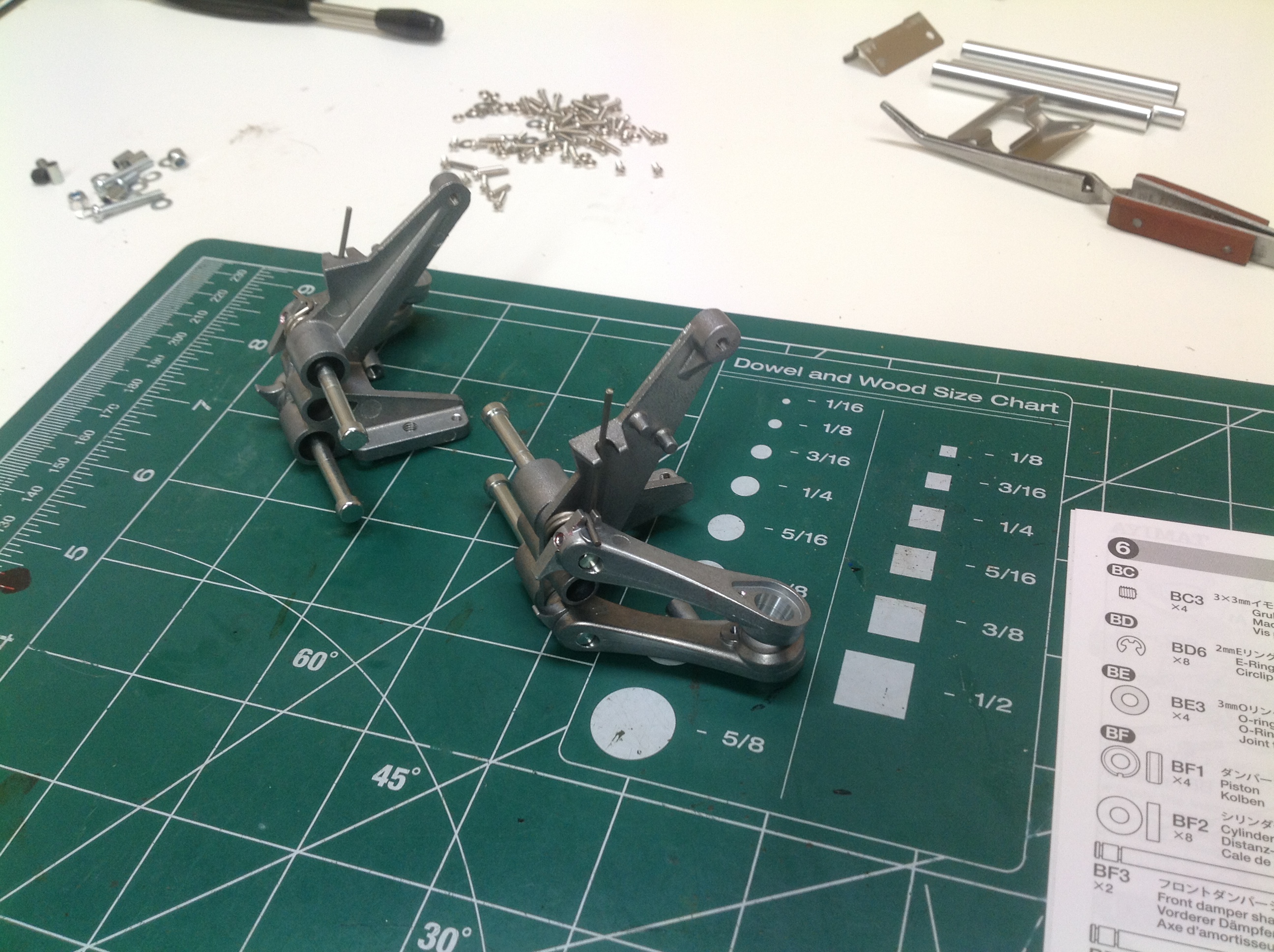
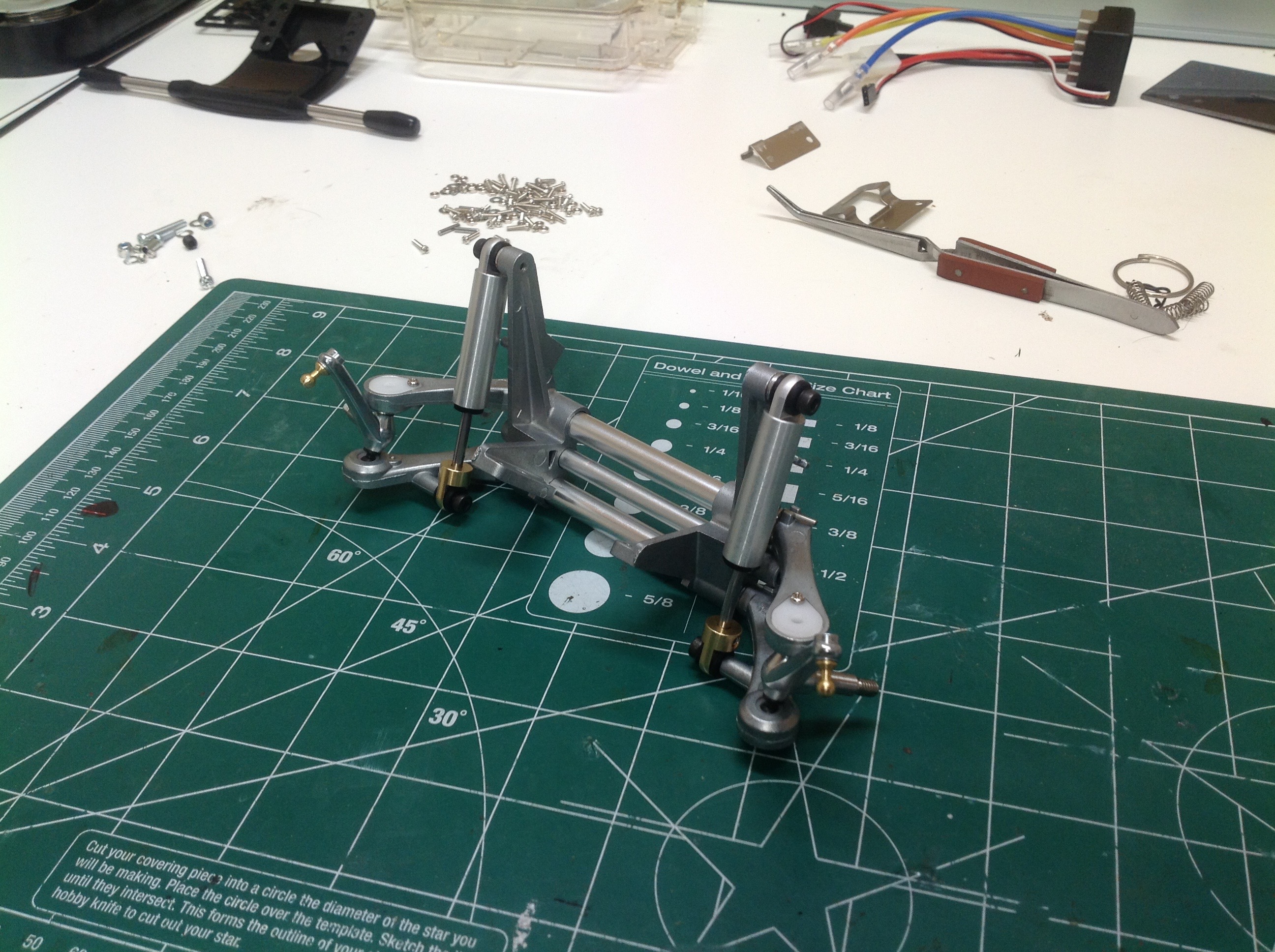
the rear suspension swing arms.  (I was going to say lower arms but there are no upper arms.)  The model uses torsion bar suspension.  The long wire you see leaving the image to the left is connected to each swing arm, and in front they are connected together to prevent rotation.  This results in a very soft, springy suspension.  I love it.  The real Beetle uses swing arm suspension like this but without a lower arm.  Instead the axle itself forms the support and thrust loads are carried by a radius arm which also connects to a lateral torsion bar.  This model uses a longitudinal torsion bar connected to the lower arm.


Now we install the motor.  This is a standard silver can 540 which is all you need for this model.  This gear mesh is not adjustable.  There is only a single pinion which works with a given spur and the motor mount is keyed to make it fit correctly.  The kit comes with two pinion and spur combinations: a high speed and a low speed.  I find the low speed to be better because it gives you more torque in the grass and still has plenty of top end.  The motor cover is plastic and is intended to keep water splashes out with little clear flexible grommets around the wires. On the other side of the gearbox you can see the clear gear cover which allows you to see the gear mesh.  Here the axle shafts are also installed and connected to the u-joints.  This completes the rear suspension assembly.


The order in which  the shocks are built is a little strange.  You start by attaching everything to the rod including the brass rod end, the rod cap, some spacers, a rod seal, and the piston.  This entire assembly is then inserted into the one piece cylinder which includes the head end cap.  A rubber grommet is placed in the lug on either end in place of a ball joint to allow some rotation.  There is very little fluid volume here, but these shocks still provide some nice damping for this light vehicle.


Now the shocks can be attached to the rear suspension.  At the upper end they attach to the metal roll bar which in turn connects to a one piece plastic rear bumper.  The bumper also incorporates a mount for the antenna.  In the original release this would have been a functional AM antenna.  That is no longer needed with 2.4GHz, but it still looks good on a beach buggy.  The roll bar also serves as a body mount.  The right hand image shows the installation of the chassis plate.  This single member must carry all bending loads between the front and rear.


Time to start building the front suspension.  This system uses a four-bar linkage, but it is mounted longitudinally instead of laterally making it a trailing arm type.  Between the right and left sides are 3 metal bars to keep everything square.  The hub spindles look a little thin, but I've had no trouble so far.  The kingpins are ball joints which snap into soft plastic sockets.  I suspect these will wear out and need to be replaced sooner or later.  The front springs are torsional coils which lock into the upper arms.  The dampers complete the assembly which is self-contained apart from the chassis.  The whole assembly is a very close match for the real VW Beetle, so much so that it is clear Tamiya had this car in mind when designing the chassis even though the Rough Rider came first.  The only difference is that the real thing used torsion bars instead of torsional coil springs.


Now here's a different kind of servo saver.  The two steering tie rods connect in the center to a plate which uses a C-shaped wire for connection to the steering crank.  If too much torque is applied the wire will open up.  Above this is the post which will serve as the forward body mount.  Finally, the front suspension is attached to the chassis plate which completes the rolling chassis.


The wheels are a 3-piece plastic design which lock the bead of the tire.  This makes the wheels and tires unique and they cannot be easily shared with other buggies.  On the right we see the simple electronic system: battery, ESC, receiver, servo, and motor.  The battery shown will not actually fit in the model though.


Here is the rolling chassis with and without the electronics box.  Enclosing everything in a semi-waterproof box makes a certain amount of sense, but it doesn't really look very good.  I actually prefer the picture on the left.  The right hand image shows the smallish space for the battery surrounded by a foam protector.  I used a 2s 1300mAh LiPo.


Here is the electronics box.  It does serve to keep everything very neat and self contained.  It can also be easily removed if you want to clean the mechanical components.  Access to the inside of the box is via four spring loaded 1/4 turn fasteners.


It is not an easy task to paint this model properly.  I started out with a base coat of white, then I masked off all the areas to stay white as shown in the left hand image.  The ellipses on the hood are the hardest to get right.  Should the vertical parts of the recesses be blue or white?  Can I mask well enough to control that?  No.  The right hand image shows all the French Blue applied.  I really like this color which I had never used for anything else.


With the masking off the paint is done.  The small thumbnail image looks OK, but if you zoom in on the full size you can see that the hood looks pretty bad.  My tape lines on the roof worked OK.  Next I went in with a silver paint pen and highlighted the rain gutters and door handles.  Finally, I attached the side mirrors and the driver figure.  The image on the right shows the final model in stock form.

Up to Index | Go to Page 2
©2018 Eric Albrecht