Tamiya Land Rover Defender Project
Page 1: Chassis Assembly
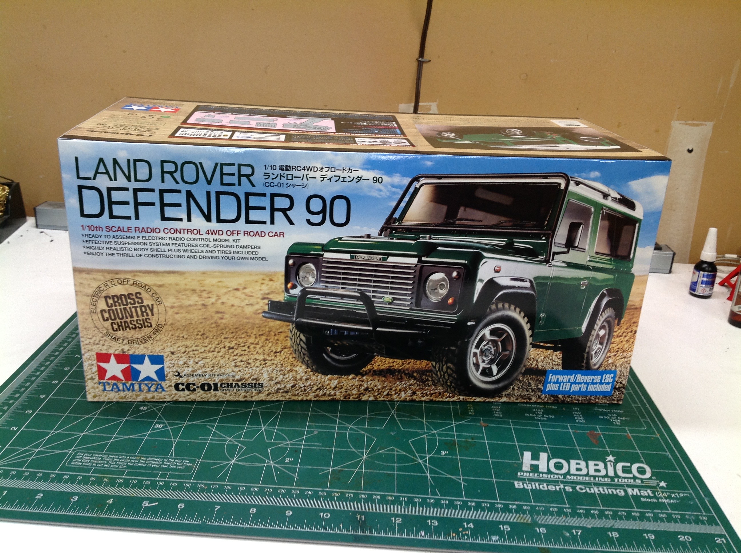
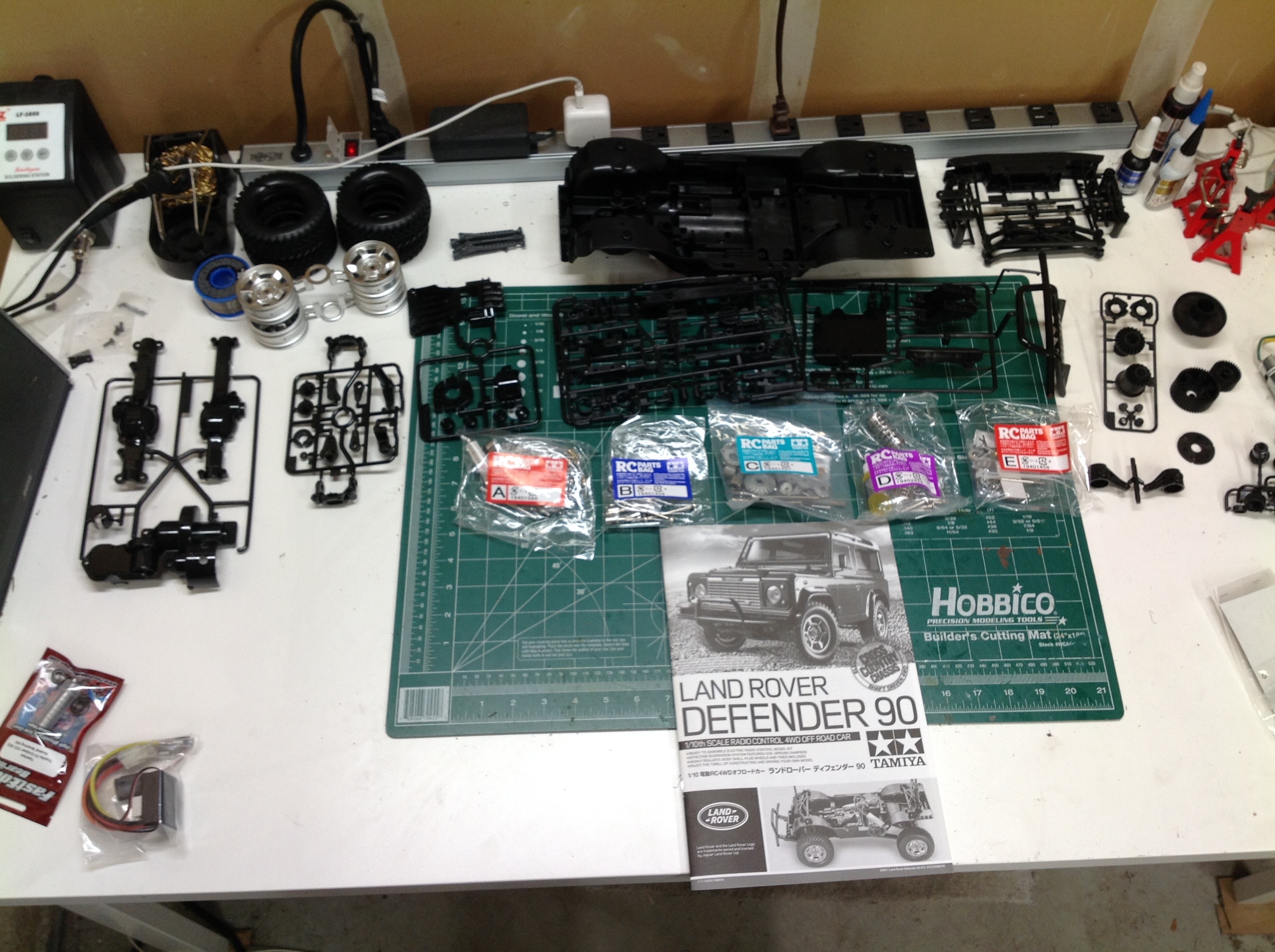
The Defender comes in a pretty small box, but it is slightly larger than
other CC-01 boxes probably due to the tall body. Inside you'll
find the one piece chassis tub along with a moderate collection of
plastic parts trees and 5 hardware bags. This set also comes with a
TBLE-02s electronic speed controller and a standard 540 silver can
motor. At the lower left you can see the set of Fast Eddy ball
bearings that I'll be adding during the build.
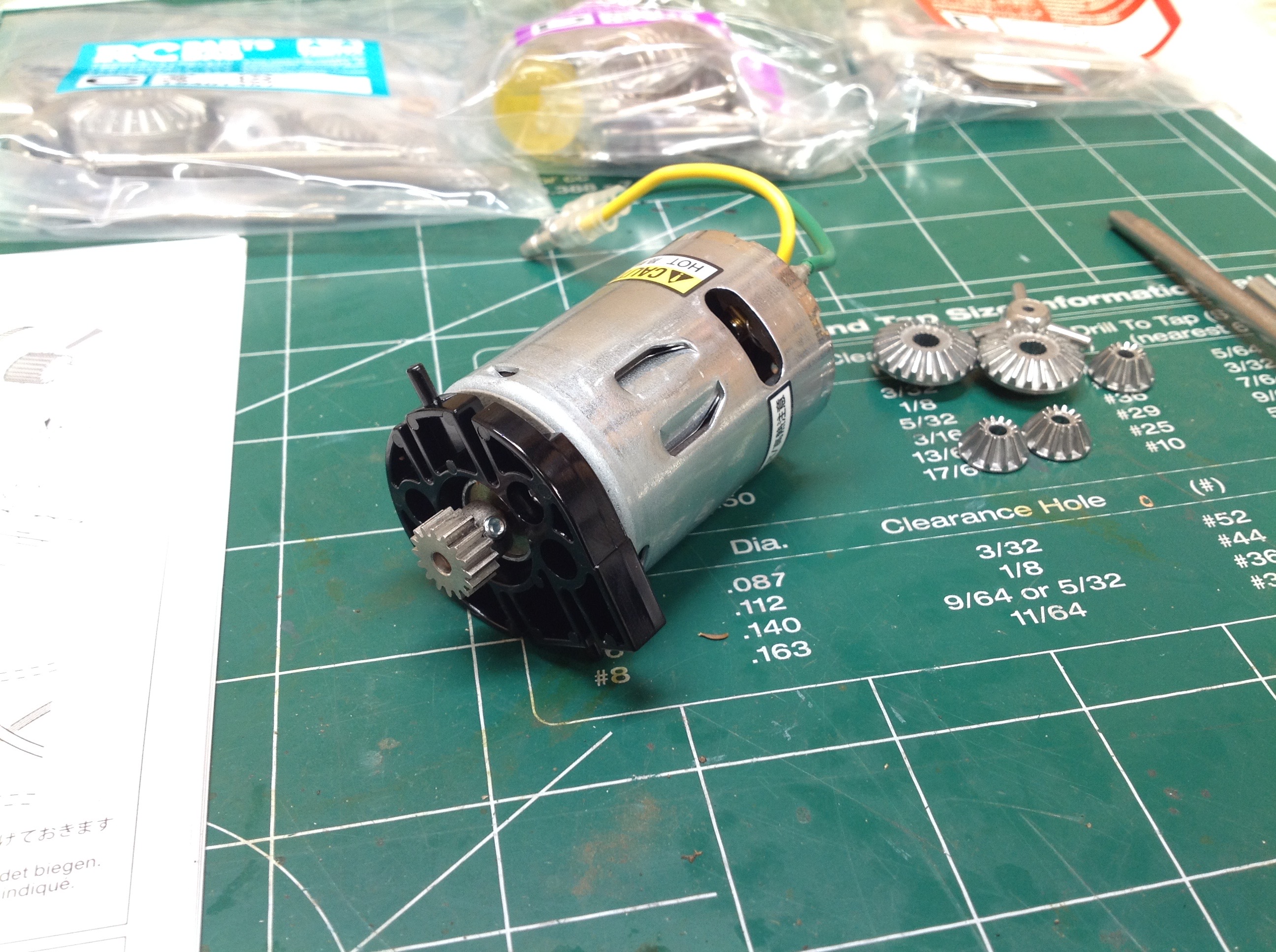
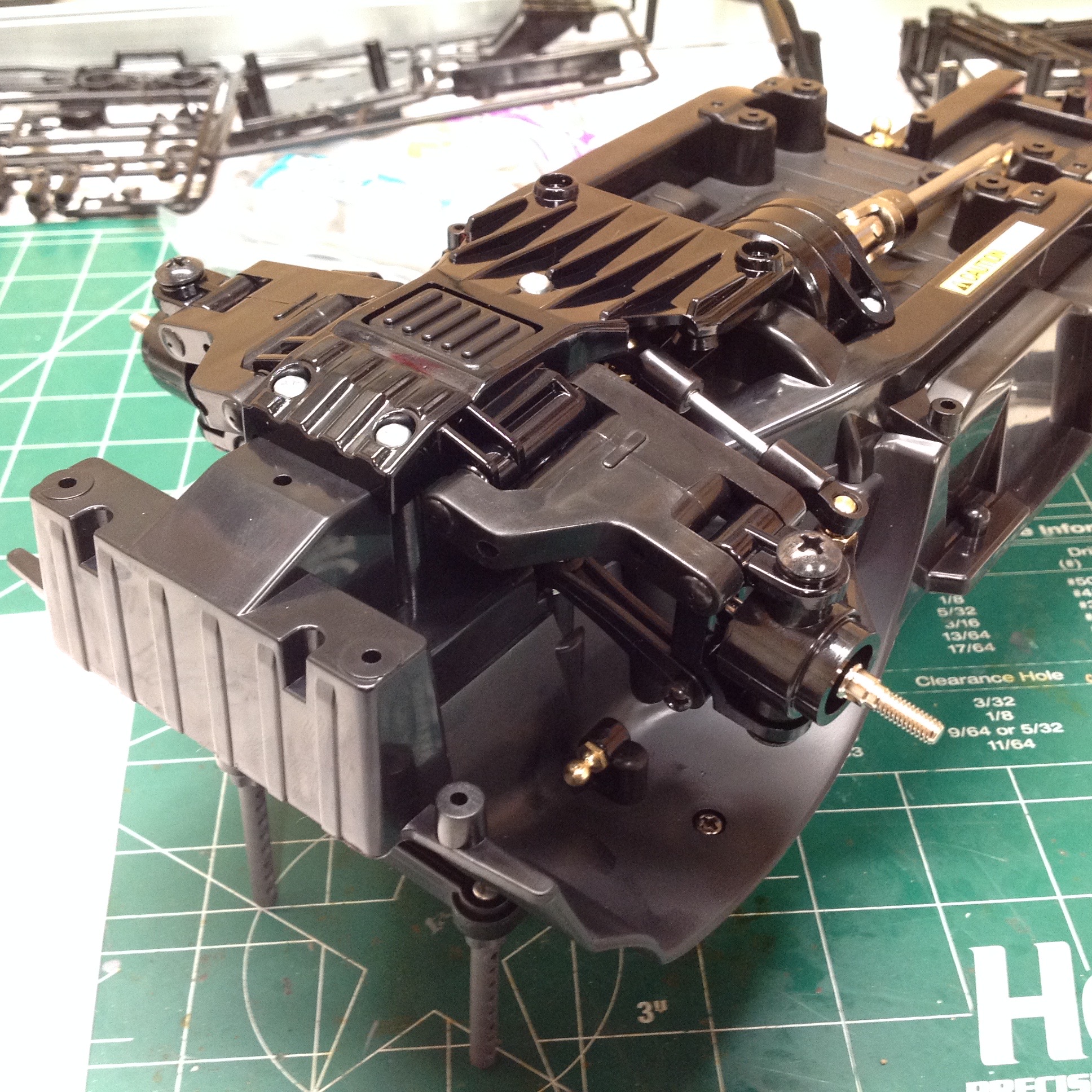
The motor mount is a non-adjustable indexed type. You can attach
the motor positioned for either of two pinions: 16T or 20T. The
kit comes with a 16 tooth pinion. The optional use of a 20 tooth
pinion would make the model much faster, but it would actually be nicer
to be able to go the other way for better crawling torque.
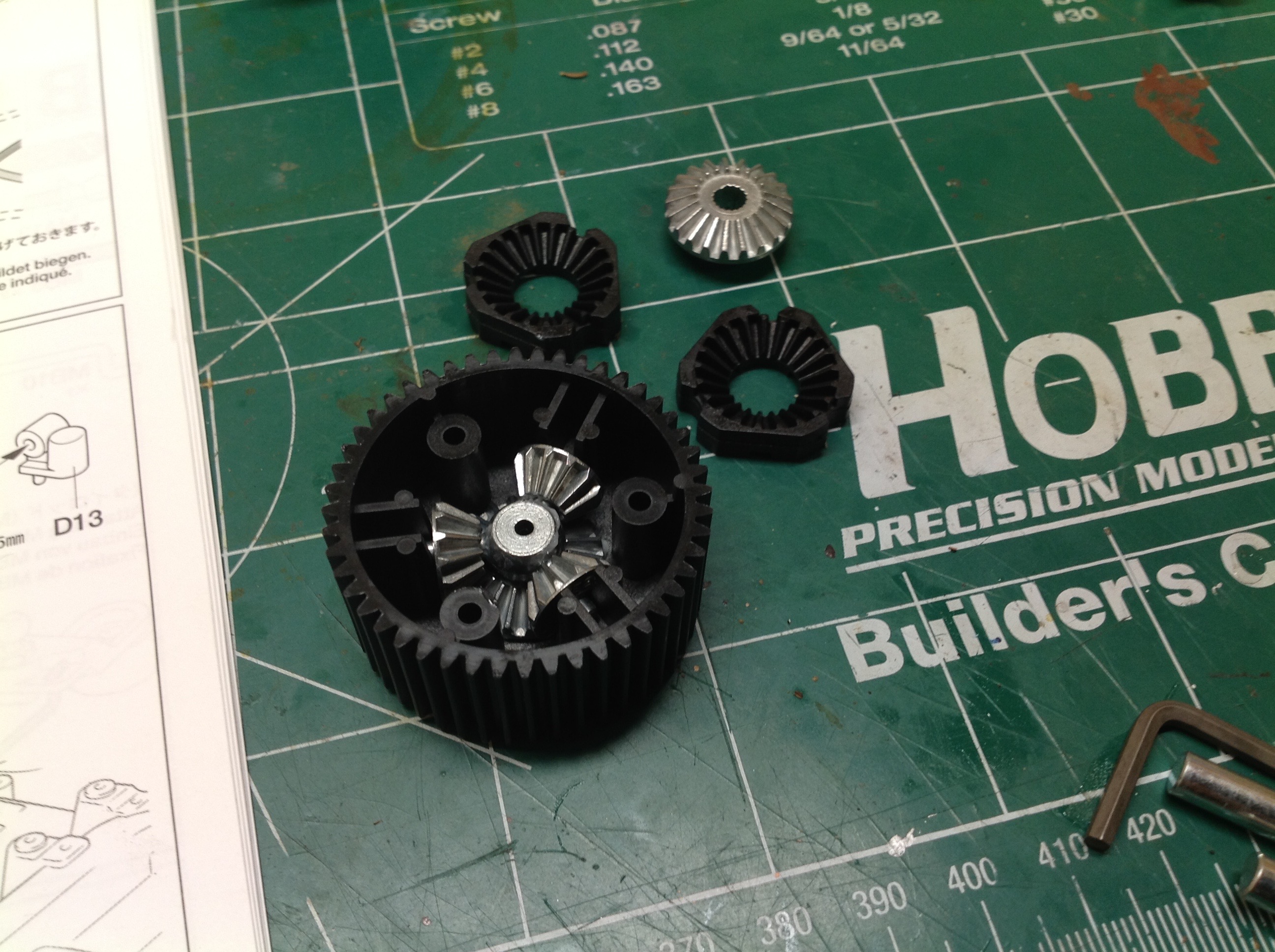
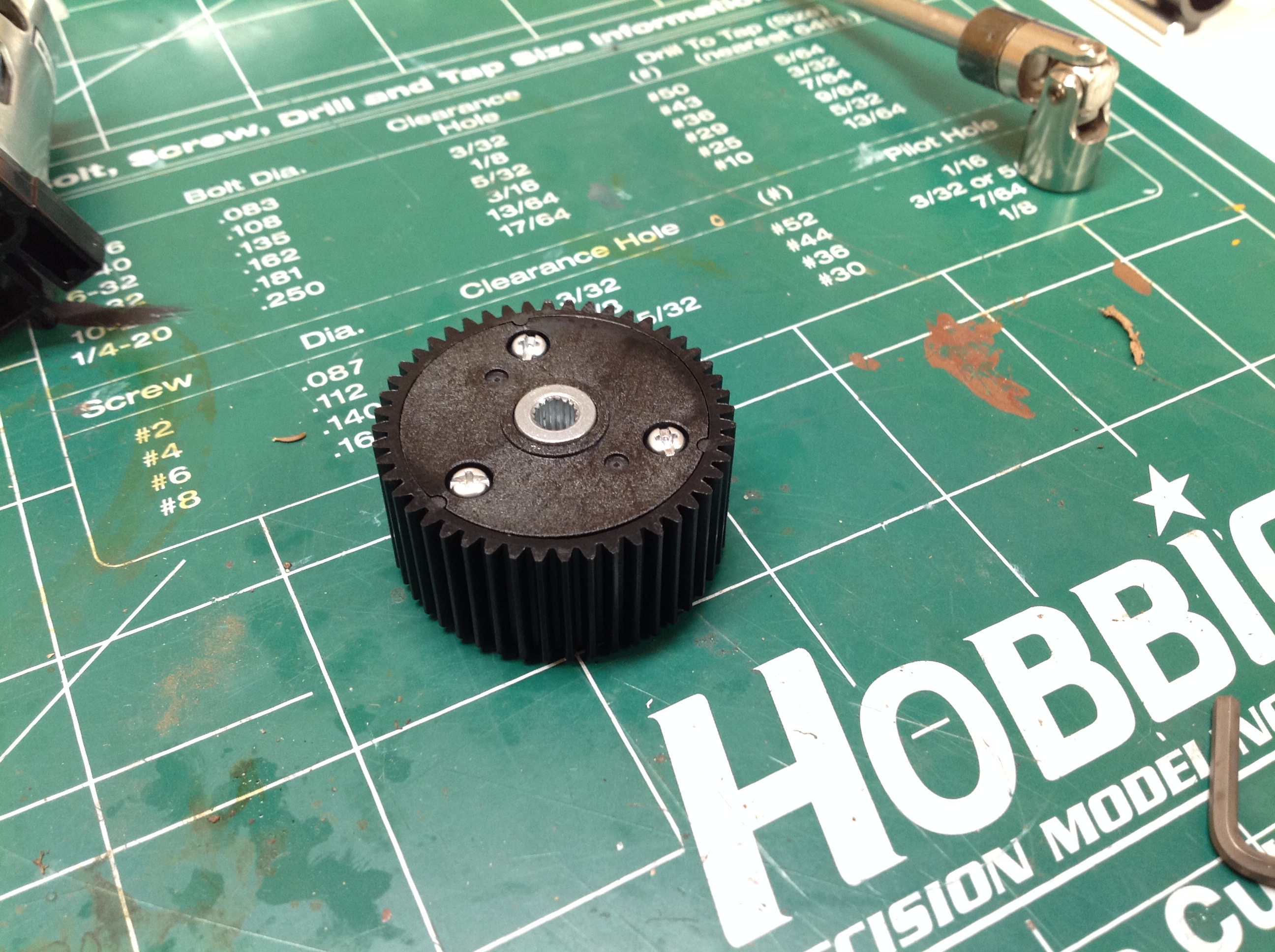
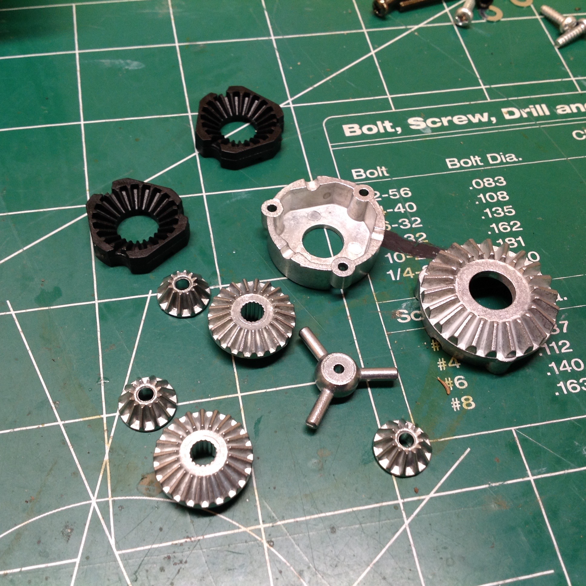
The front differential uses a large plastic spur gear housing a set of
cast metal spider gears. As you can see, the spur gear teeth are
enormous and shouldn't strip under any power that could reasonably ever
be applied.
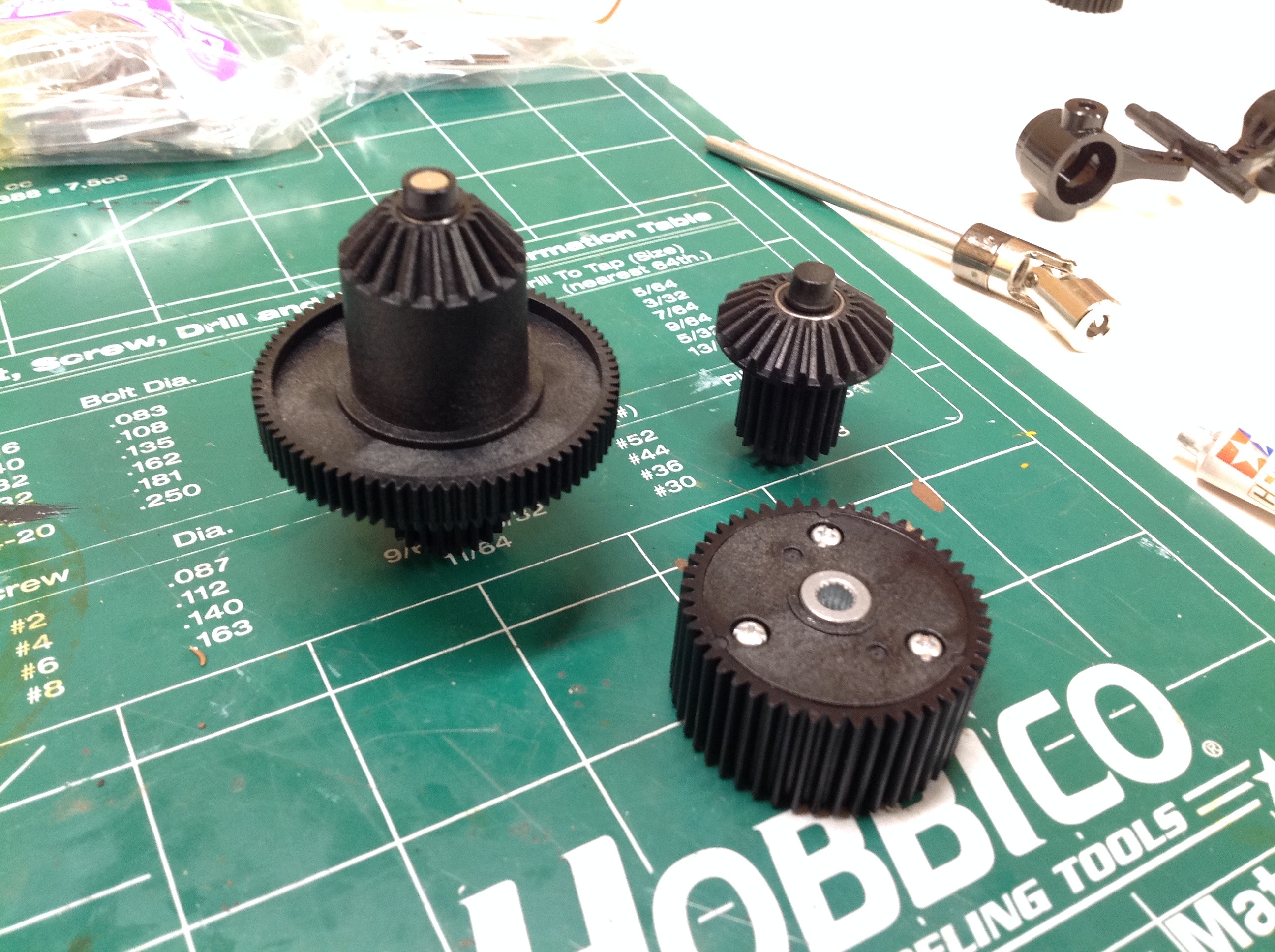
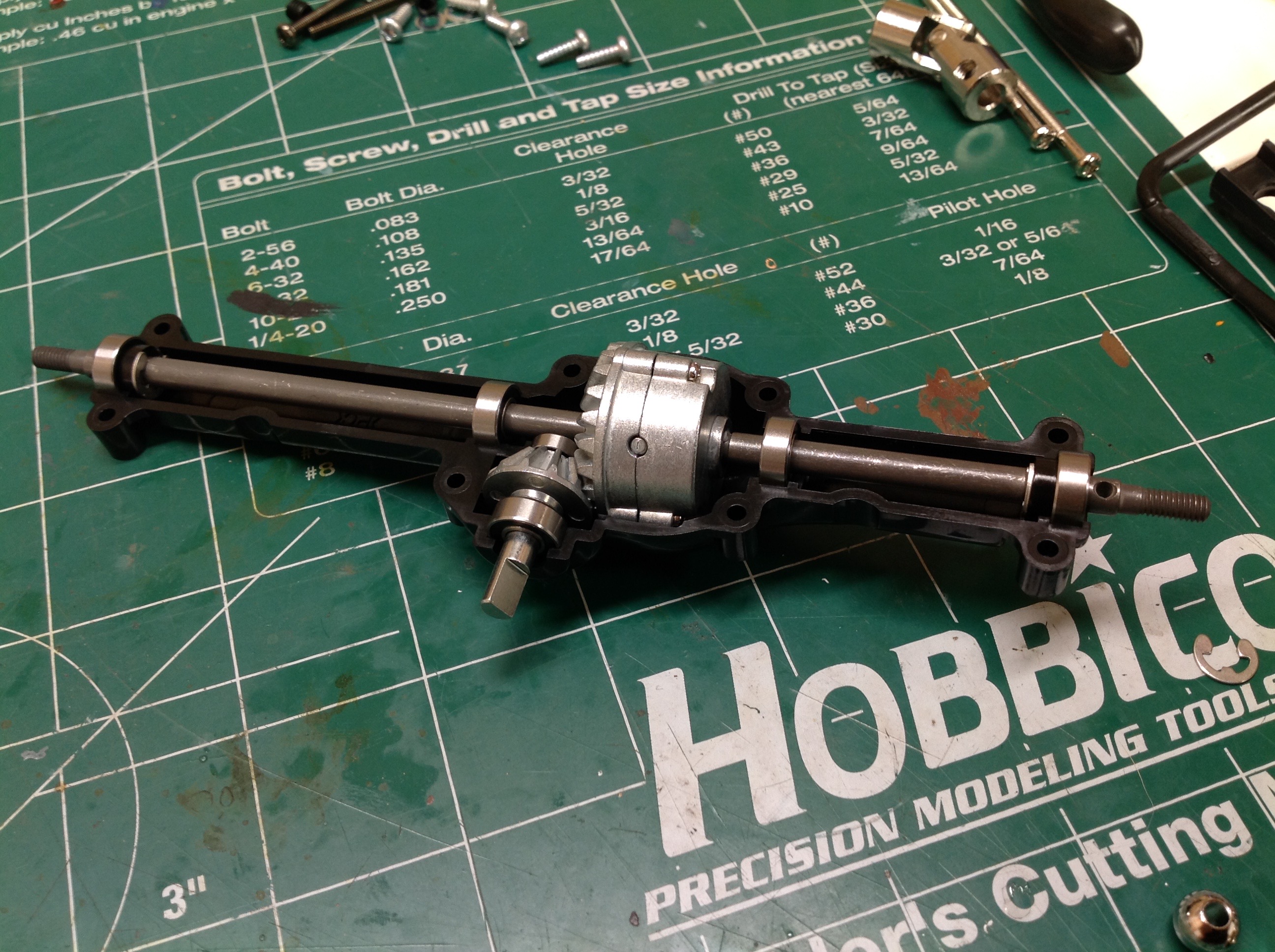
The spur gear which mates with the motor pinion shares a shaft with a
large bevel gear. On the right you can see the path from the motor
to the front differential (which you may recall is housed in the large
plastic gear at the front). The pinion drives the spur which then
makes a right angle turn before another set of reduction. The gear
which you can see next to the motor will be used for the rear
axle. All of the gears are nestled tightly in the chassis tub safe
from debris.
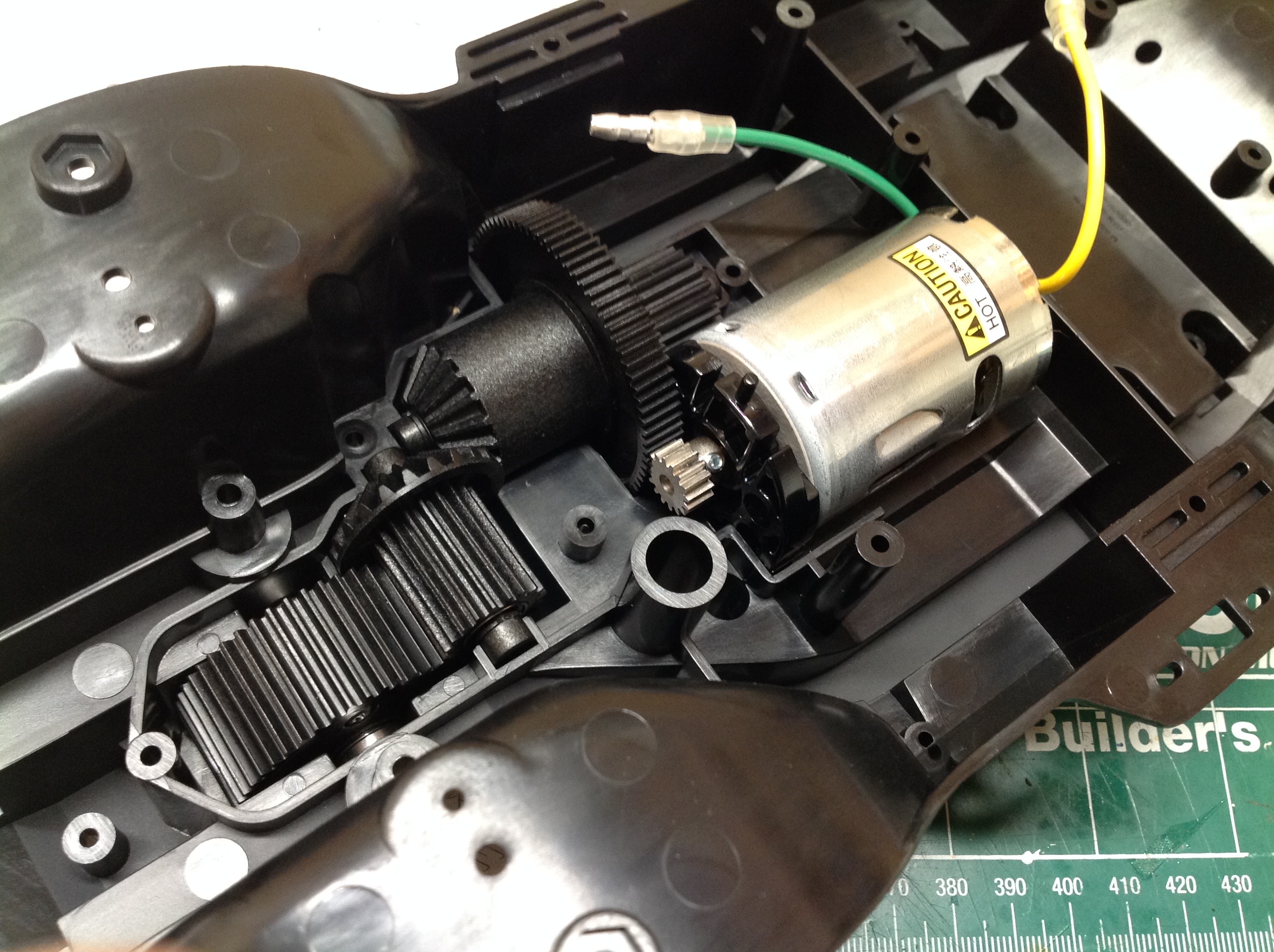
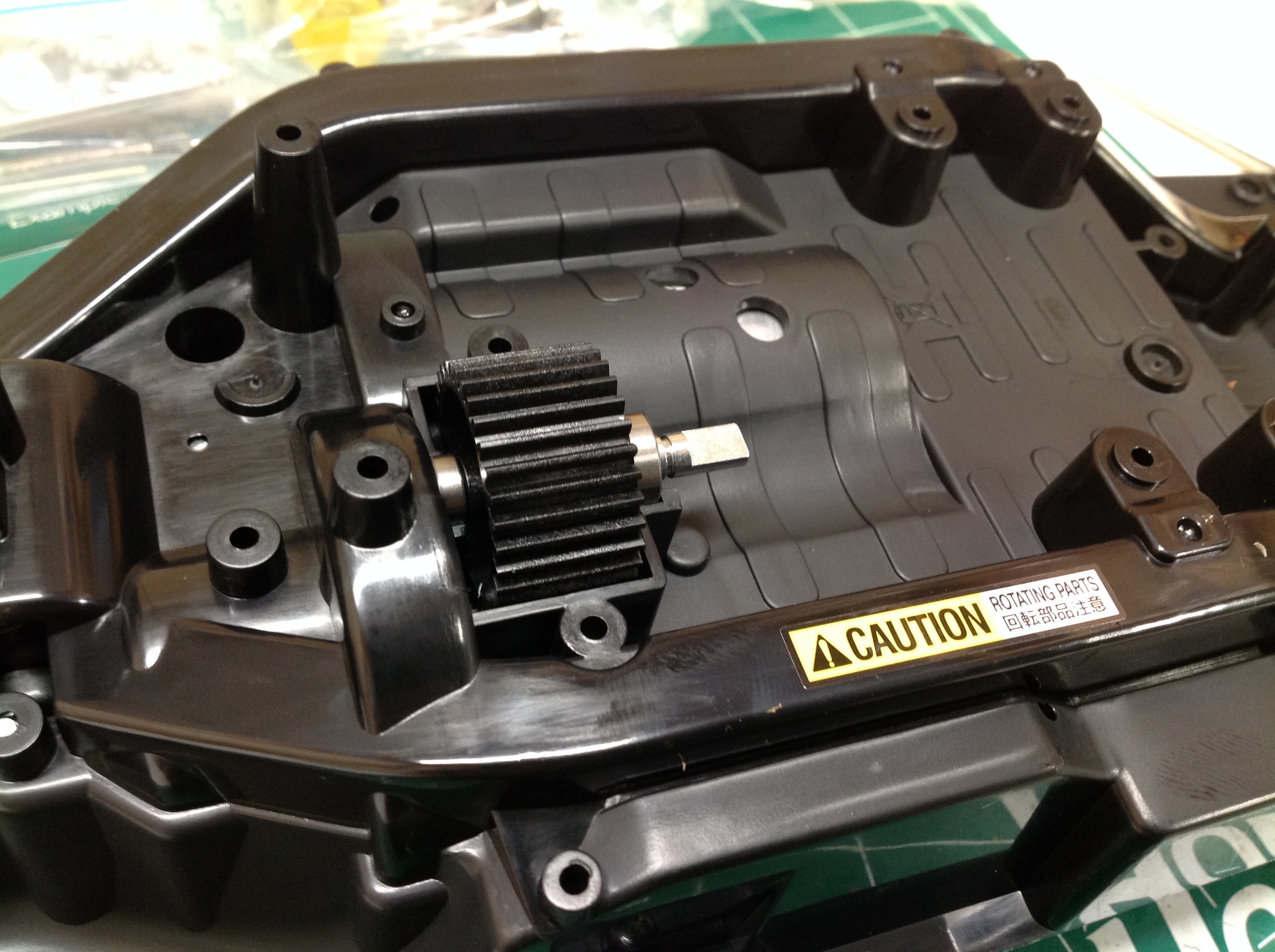
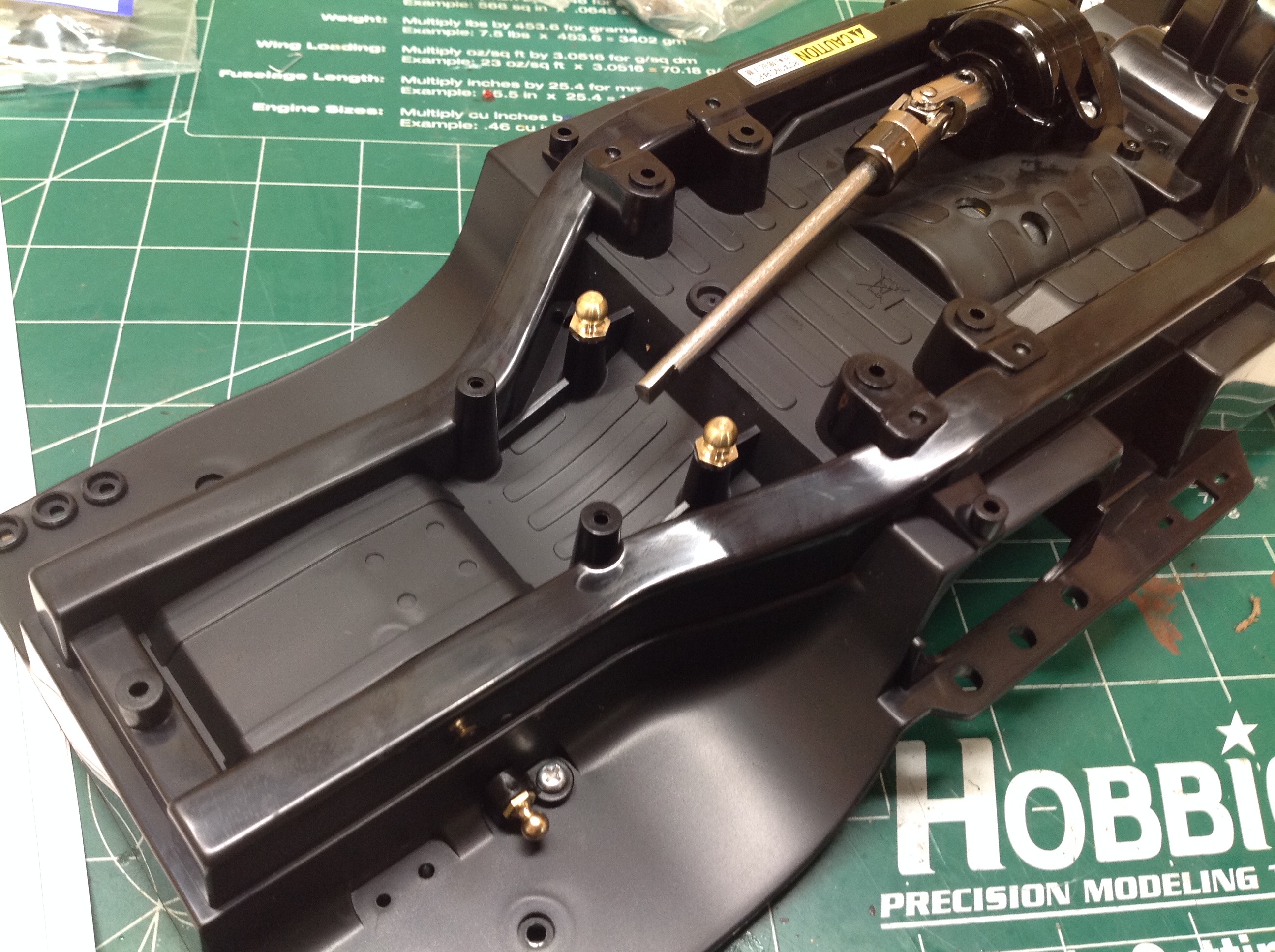
This view from the bottom of the chassis tub shows another gear which
sits beneath the main spur. This will be used to drive the rear
wheels. On the right the cover has been installed and the rear
drive shaft attached. This is a nice steel telescoping unit.
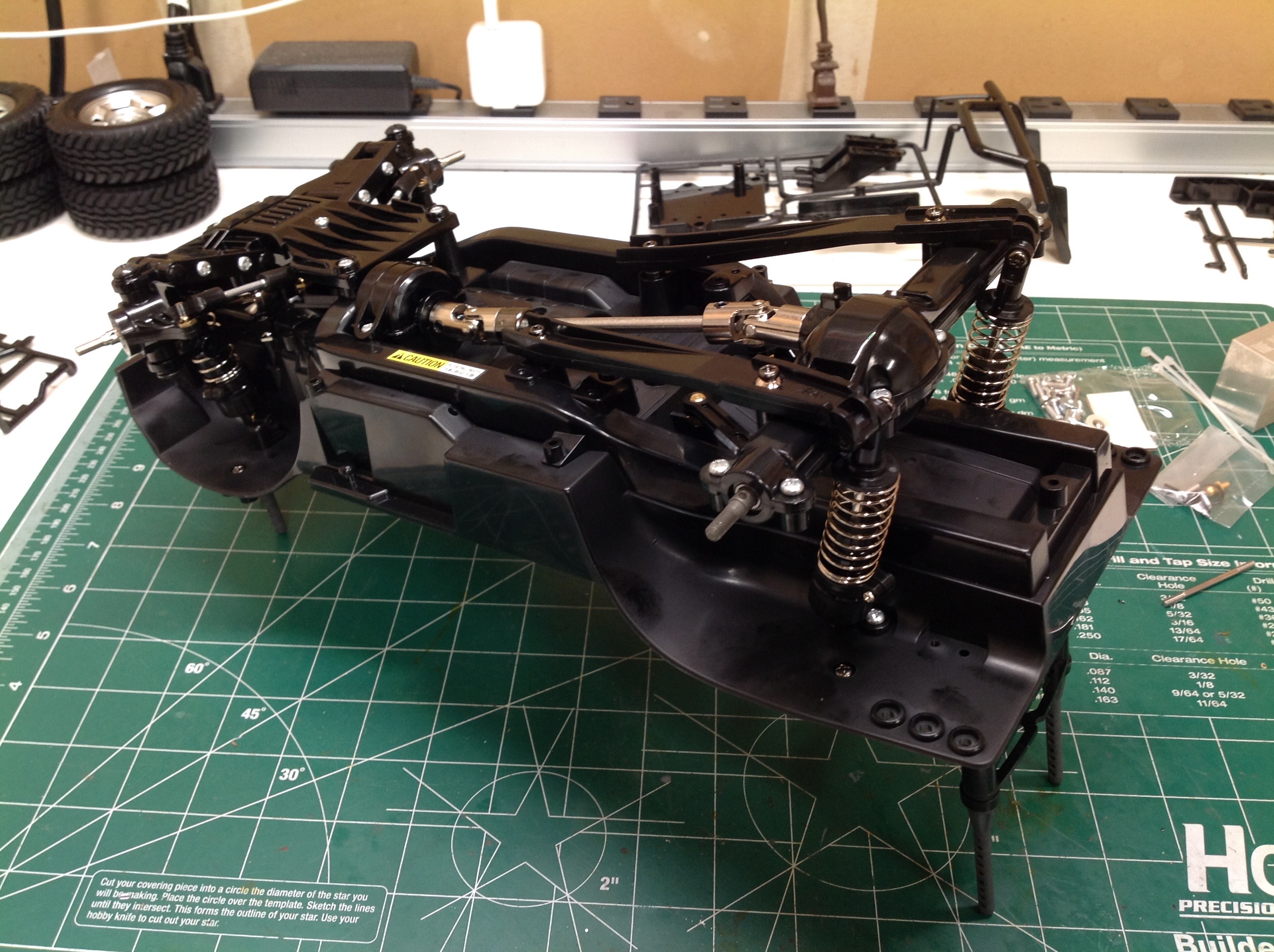
In this picture you can also see the provisions for different
wheelbases. The brass ball joints shown will be used for the upper
links. The holes further forward are for the lower links, and the
holes further back are for the shocks. In each case you can see
two sets of holes which allow variable wheelbases.
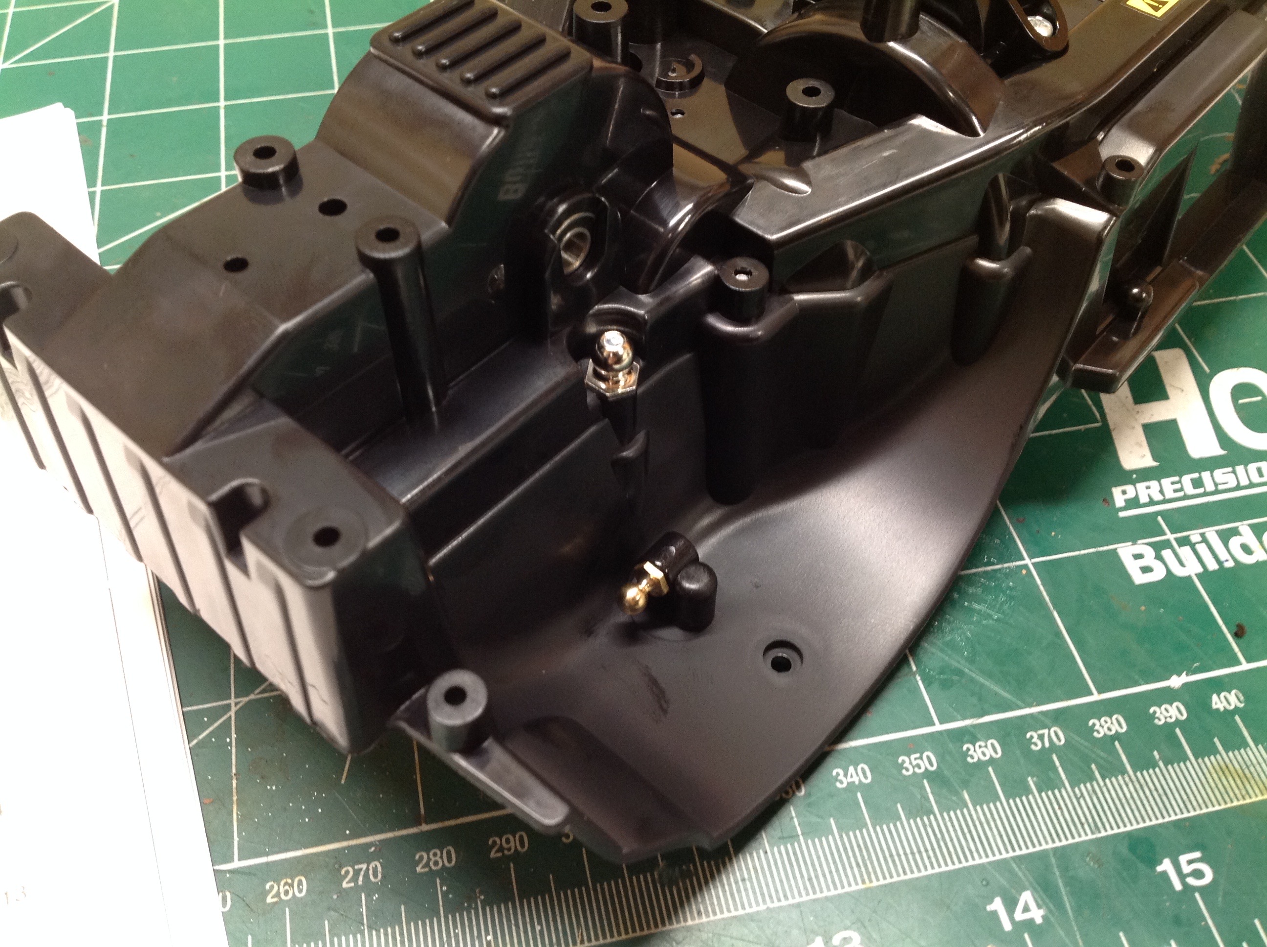
Here are the ball joints for the front suspension viewed with the
chassis inverted. The balls at the top of the wheel well are for
the shocks, and the others are for the upper control arms. Just
behind those balls you can see the hole in the side of the differential
where the axle shafts will come out.
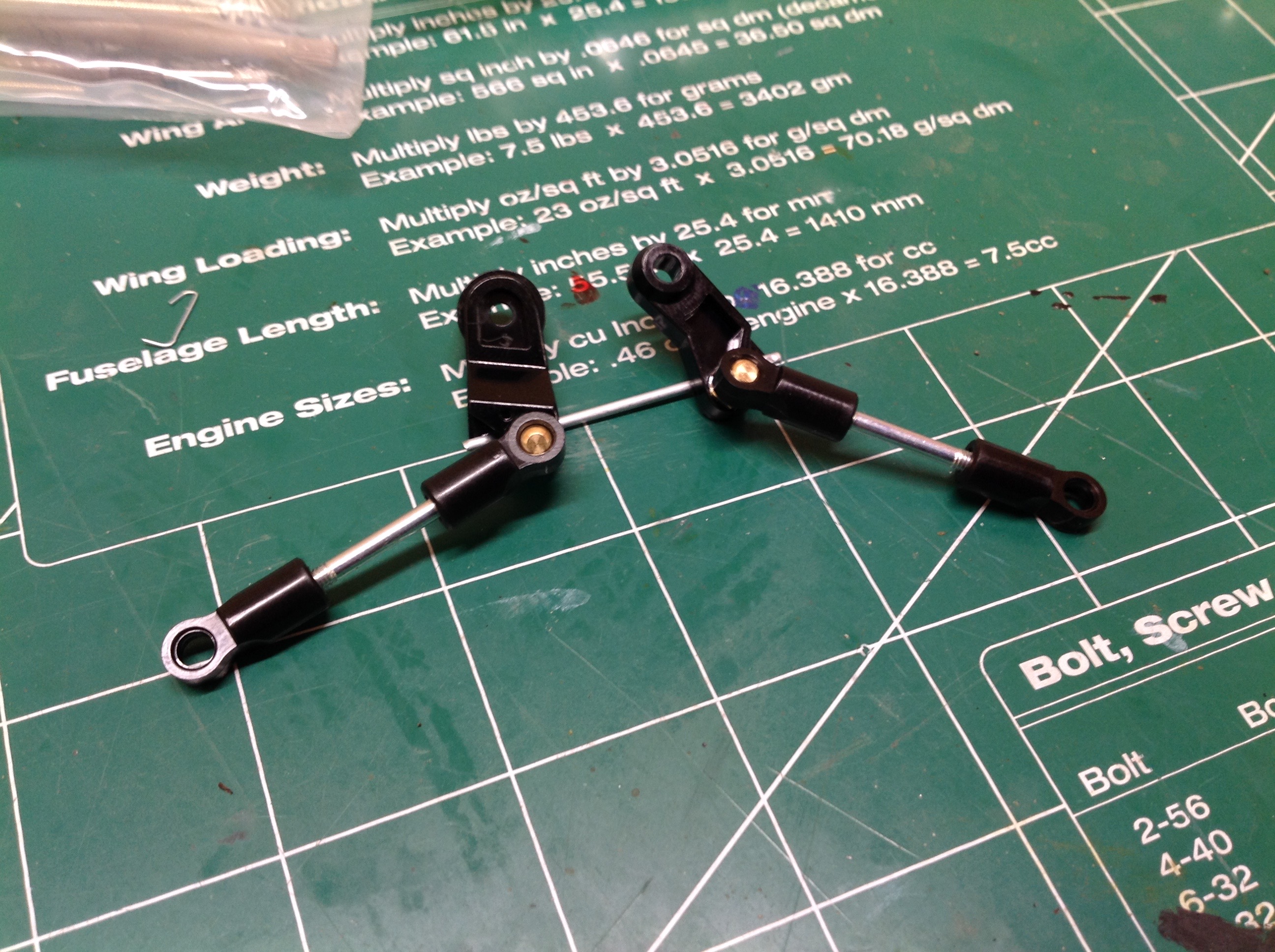
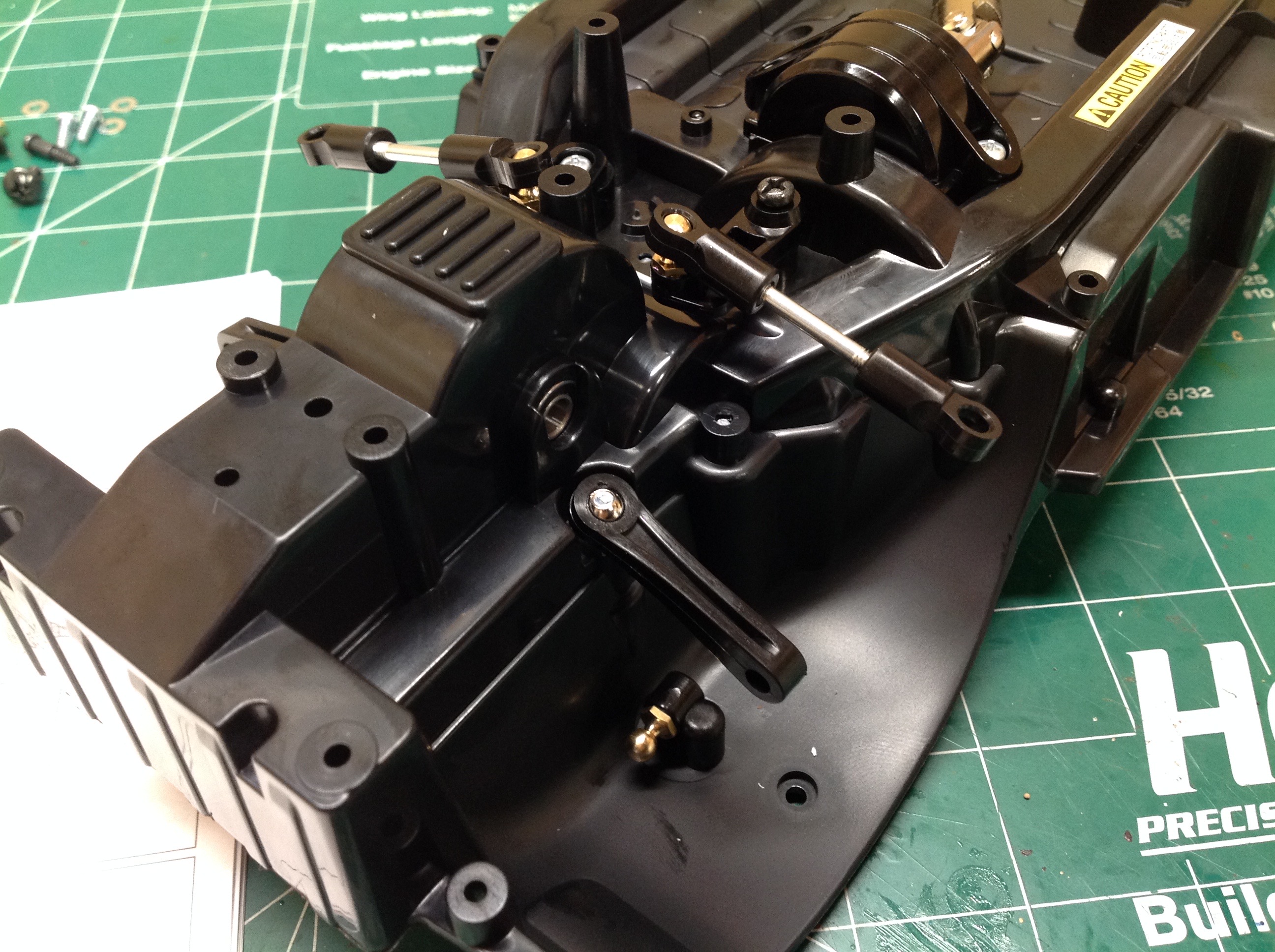
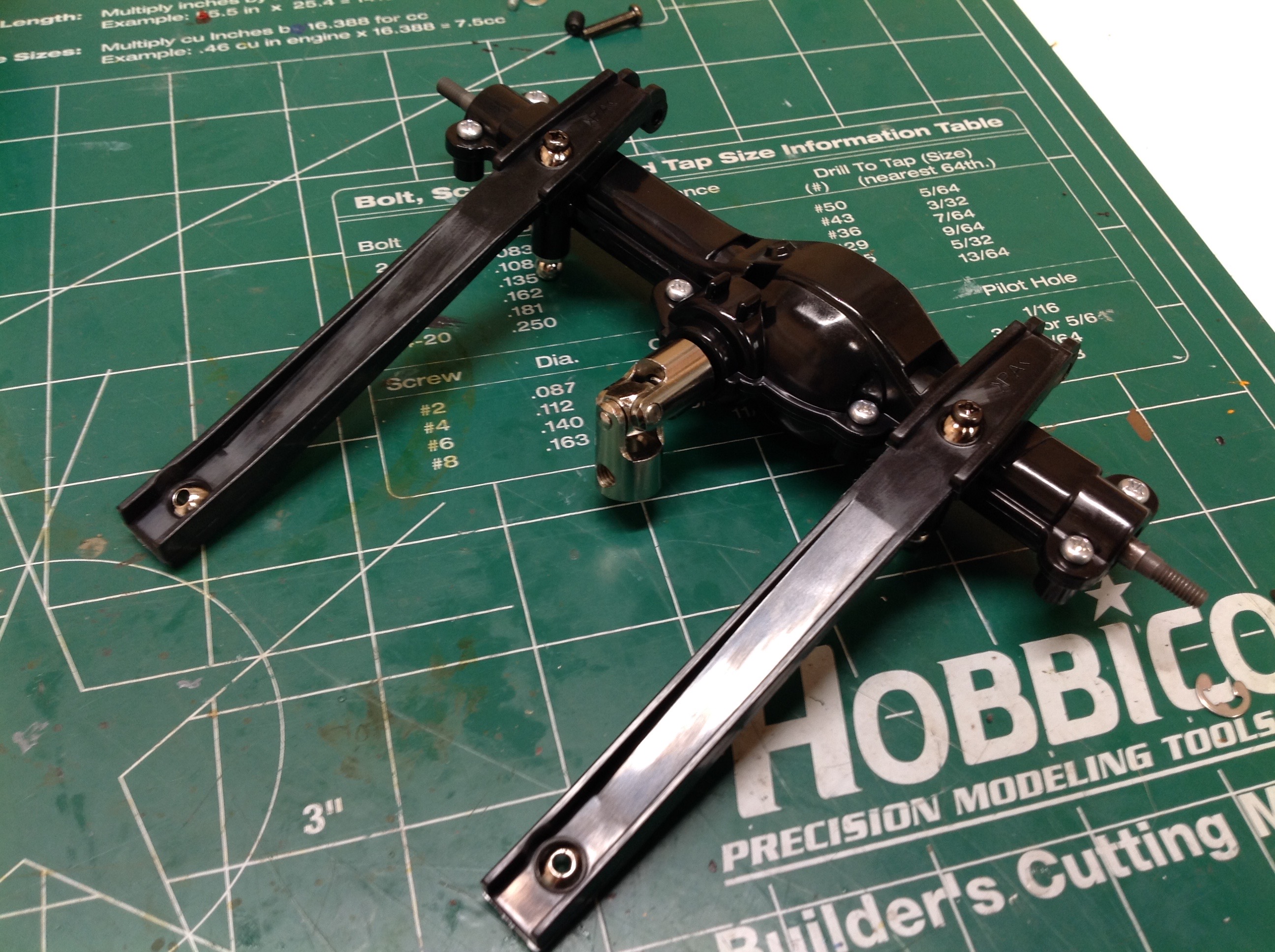
Next we'll install the front suspension and steering. The left
hand image shows the dual bellcranks for the steering. The right
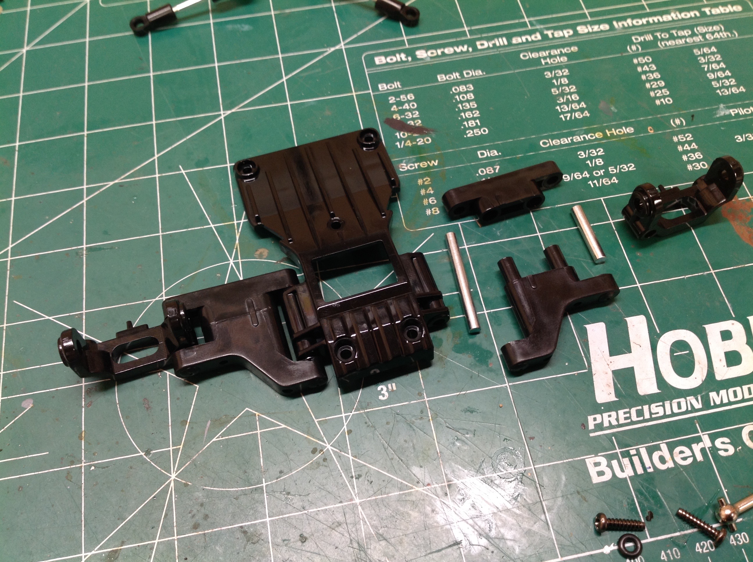
hand image shows how the lower front suspension is built. Each
control arm is built in two parts and is pinned at the inboard and
outboard ends. A C-hub is used to hold the steering knuckles.
The lower control arms (which are just fixed length rods) and steering
assembly are installed into the chassis tub. Then the lower suspension
assembly is installed which doubles as a skid plate. Dogbones drive
the stub axles. The kingpins are large step screws.
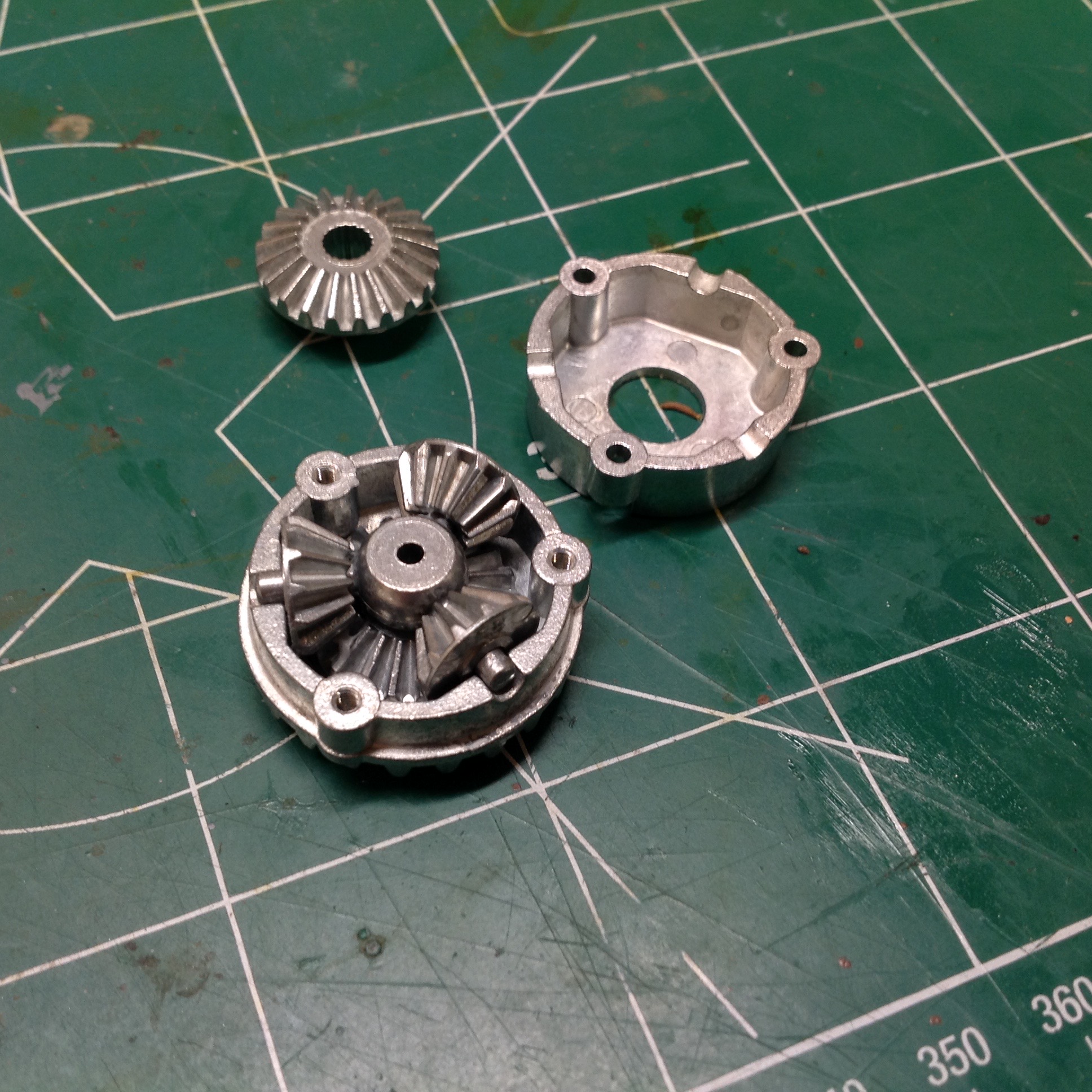
The rear differential is quite different than the front. It uses
the same metal spider gears, but they are installed into a metal bevel
housing instead of a plastic spur housing. Because the rear has
the extra reduction at the ring and pinion compared to the front, it is
tricky to get them to have the same overall ratio. The plastic
gears you see in the background can be used to lock the rear
differential.
Now we'll build the rear axle. The first image shows the ring and
pinion gears installed along with the solid axle shafts. After the
axle housing is buttoned up, the plastic lower suspension links are
installed. These are nice and wide to slide on rocks without
catching or breaking.
Now the rear suspension is complete. The upper links are much
shorter fixed links and are more greatly triangulated to keep the axle
centered. The overall articulation angle is quite large.
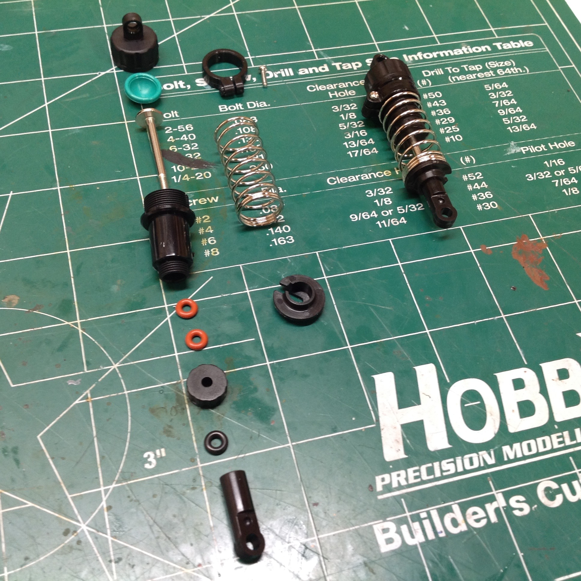
Time to build the shocks. These are plastic oil filled shocks but
are not quite the same as standard CVA shocks. The main difference
is that they do not have interchangeable pistons attached with
E-clips. Instead, the piston and rod are a single, monolithic
metal part so the only adjustment possible is fluid viscosity. The
right hand image shows the shocks installed. I find them quite
capable.
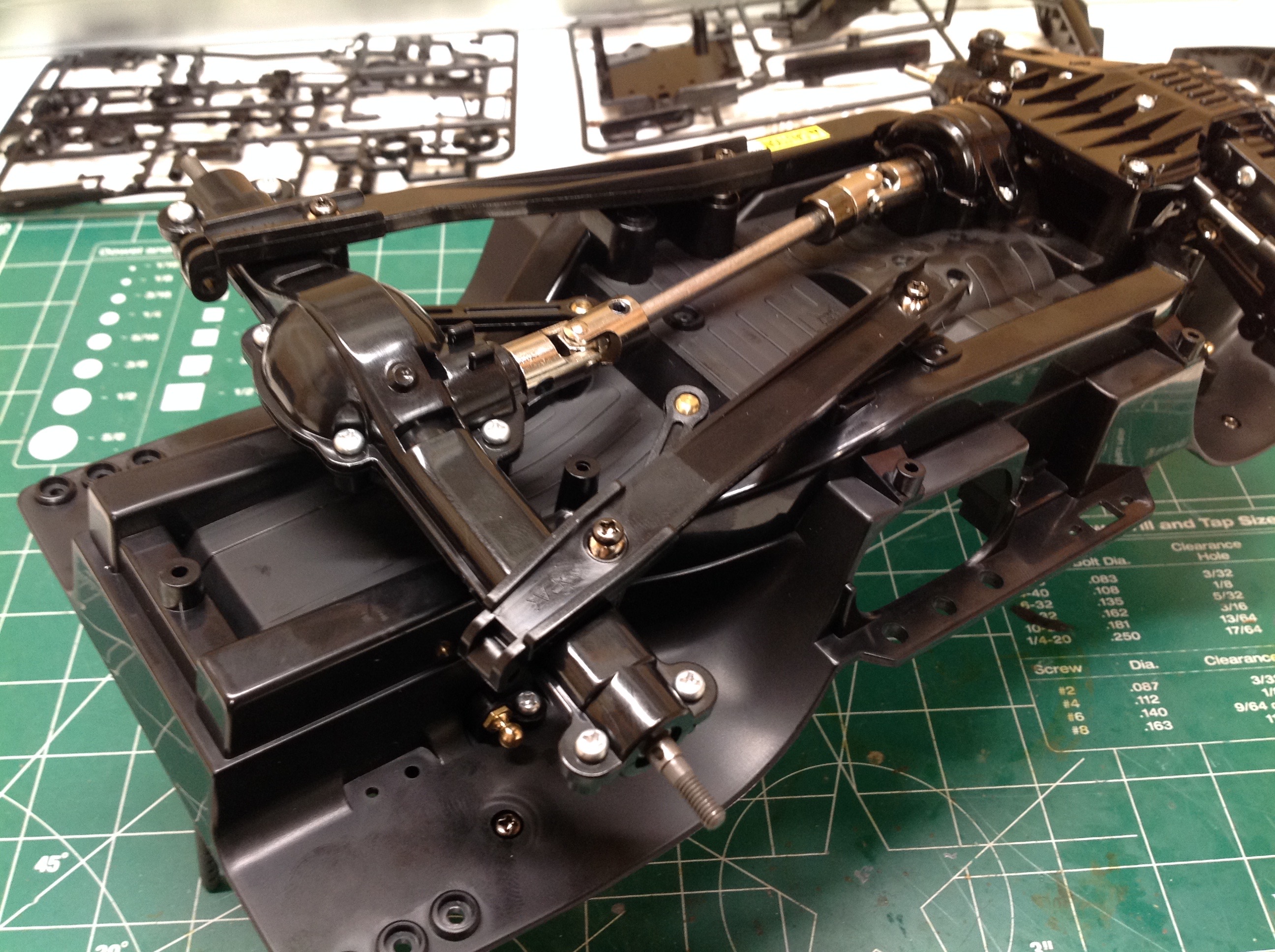
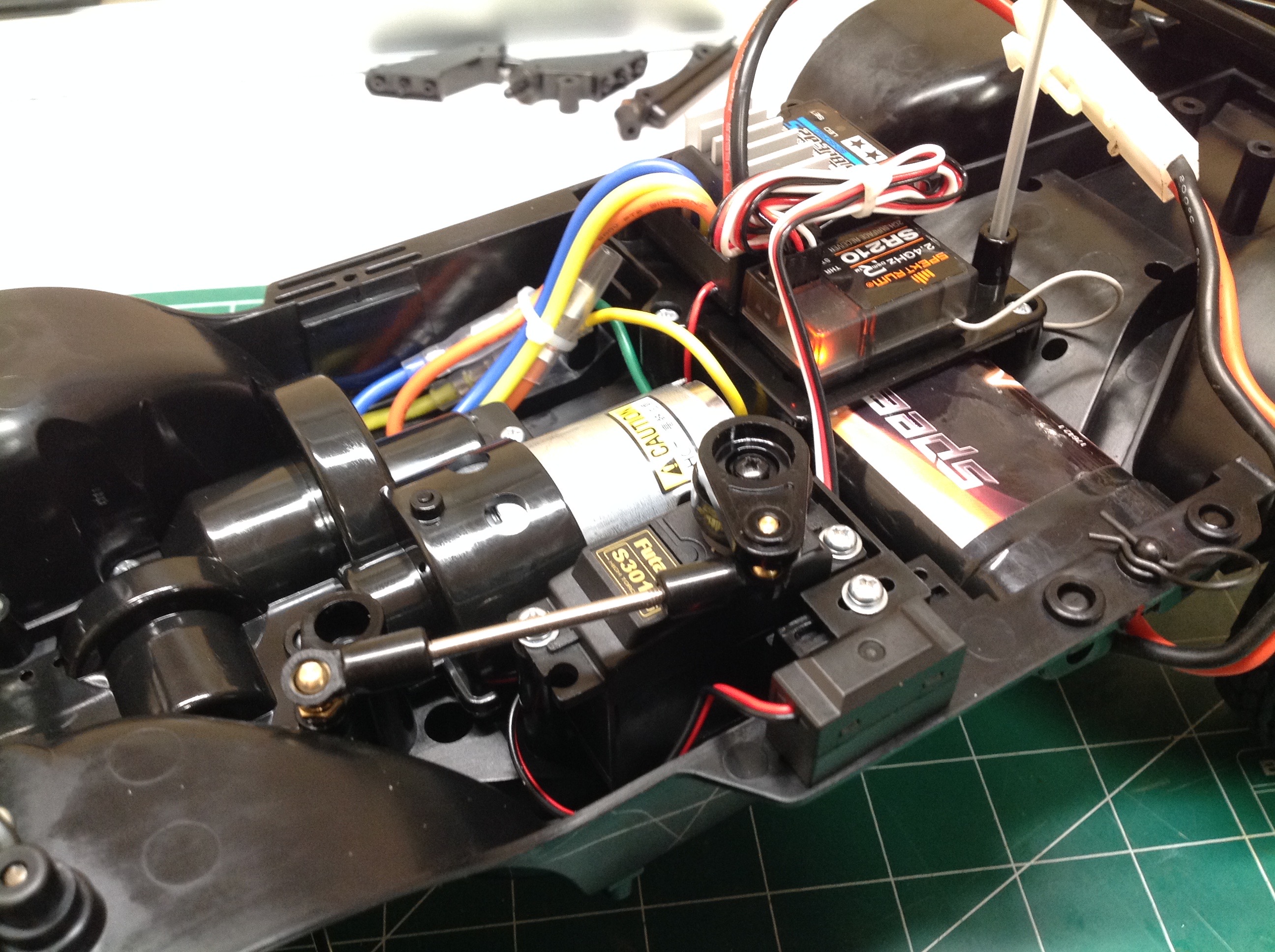
The last thing to do to get a rolling chassis is install the
electronics. The battery sits crosswise with an electronics
platform over the top. Only a 6-cell NiMH pack or something of
similar size will fit. The steering is the weakest point of the
model. Since the servo is on top but the bellcranks are on the
bottom, the torque must pass down through a long shaft which introduces
quite a bit of play. This is a really new kit though, and the
parts seem to fit better than on some older CC-01's. Perhaps they
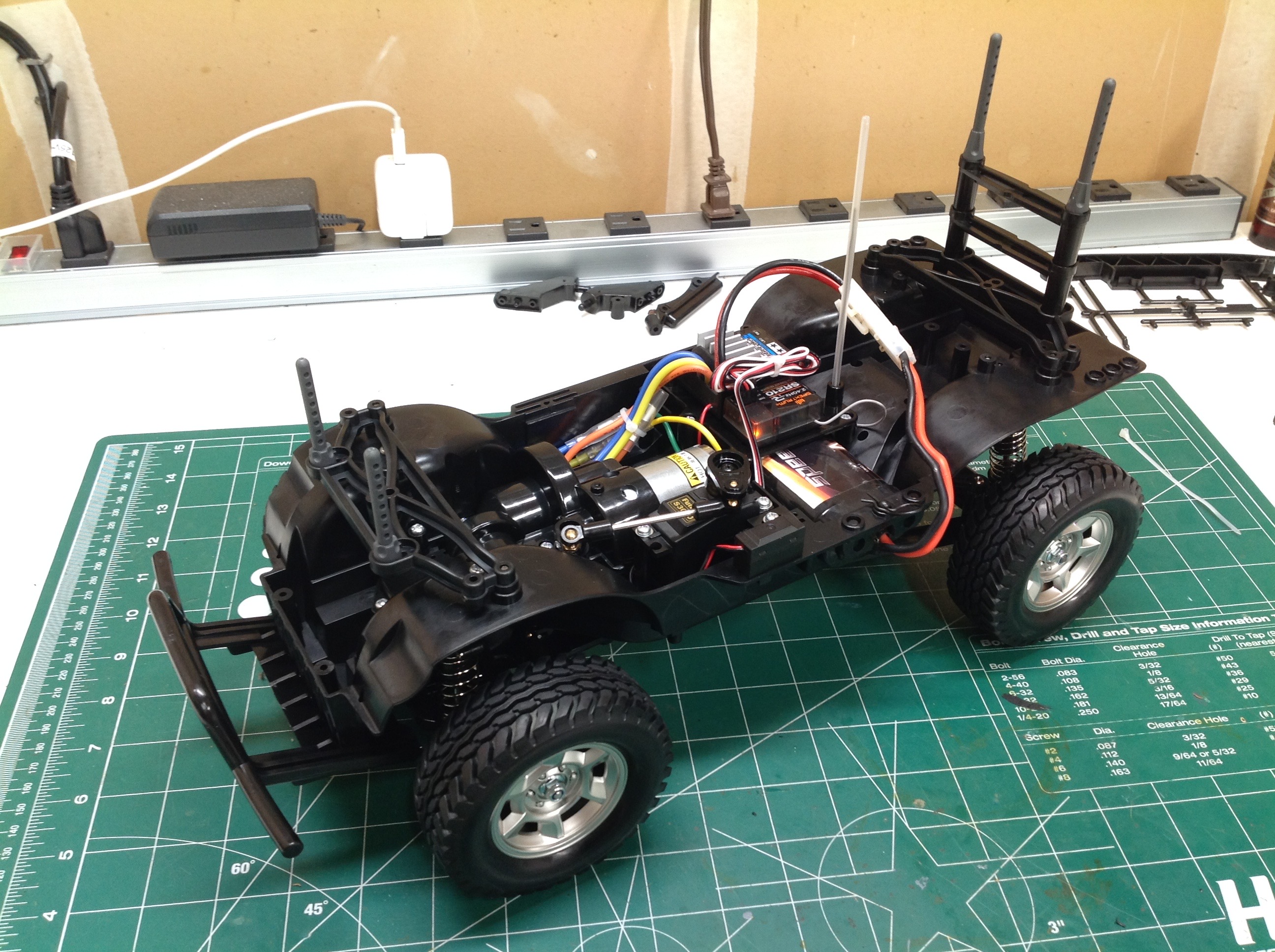
updated the mold. On the right you can see the completed chassis
with body posts, wheels, and tires.
©2018 Eric Albrecht