Tamiya Formula E Project
Page 1: Chassis Assembly
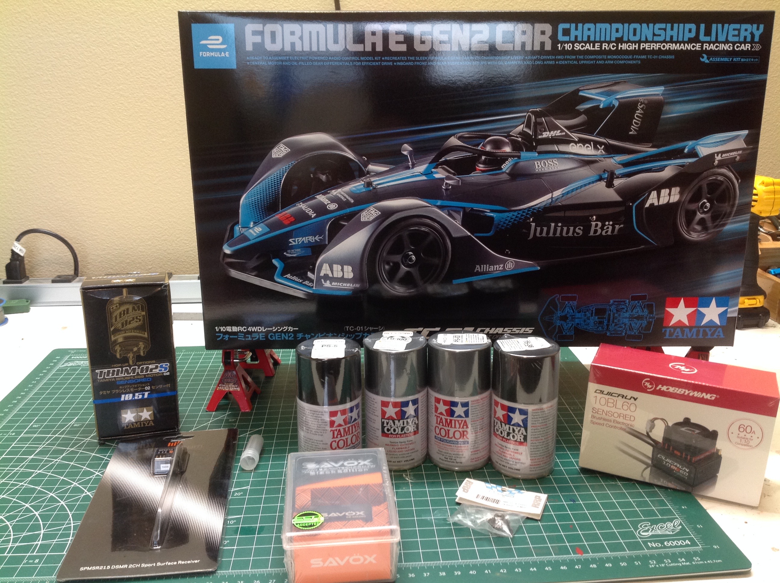
The image on the left shows the entire pile of stuff that was gifted to
me. It is hard to think of all the things which will be needed to
build a model including all electronics, paint, and bearings but my
friends did an excellent job and I didn't have to buy a single
thing. The picture on the right shows the contents of the box
don't look like anything. A lot of work is needed to turn this
into a racing car.
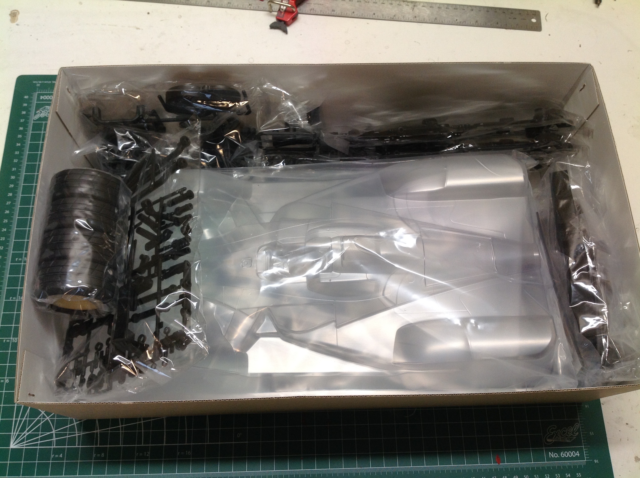
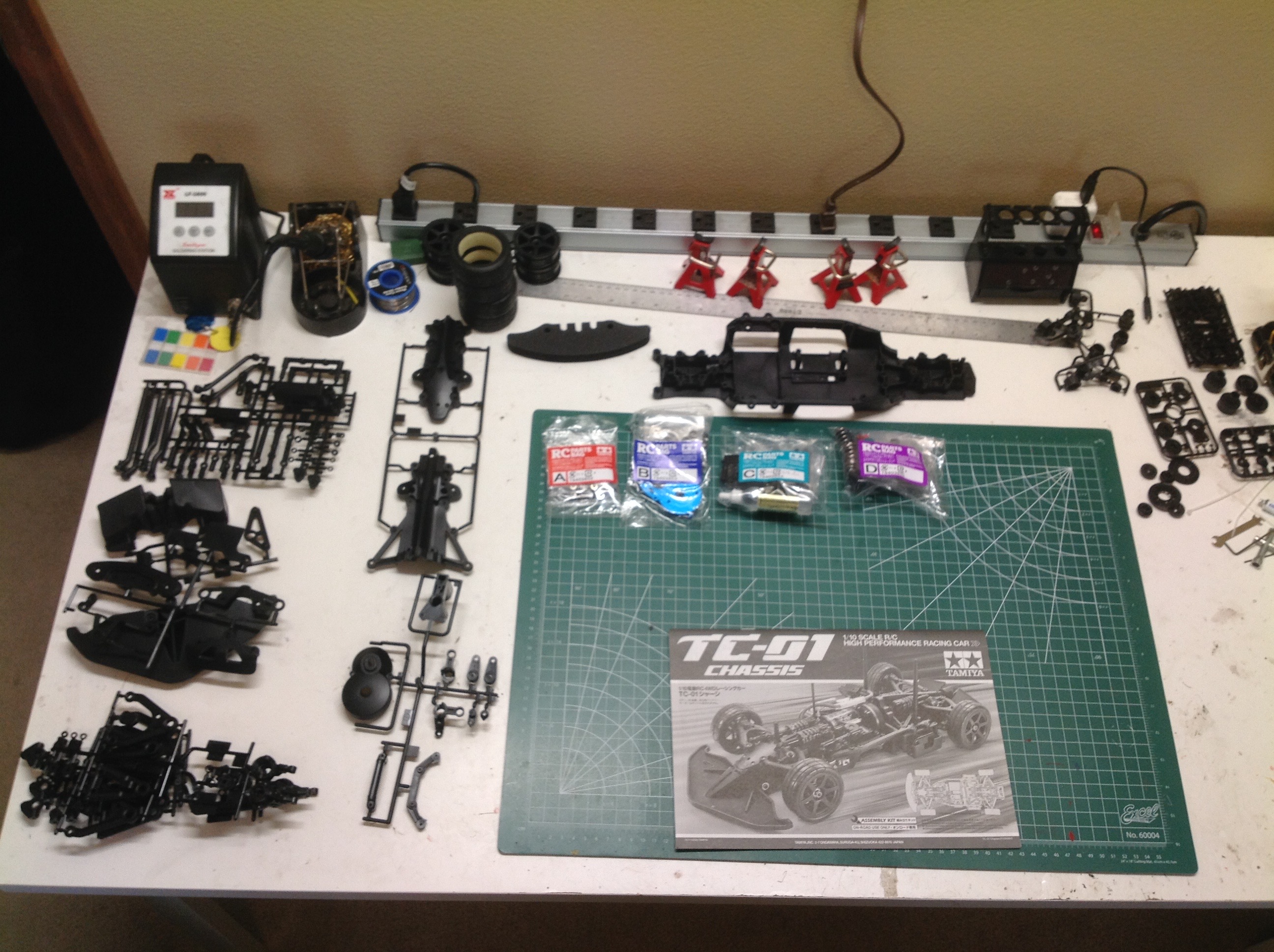
Here are the contents of the box. A large part of the overall
parts volume consists of body parts which are still in the box.
Even so, this model has a vast number of parts. This is a
complicated chassis that should be a joy to build. There are four
labelled hardware bags which are used sequentially (only one open at a
time).
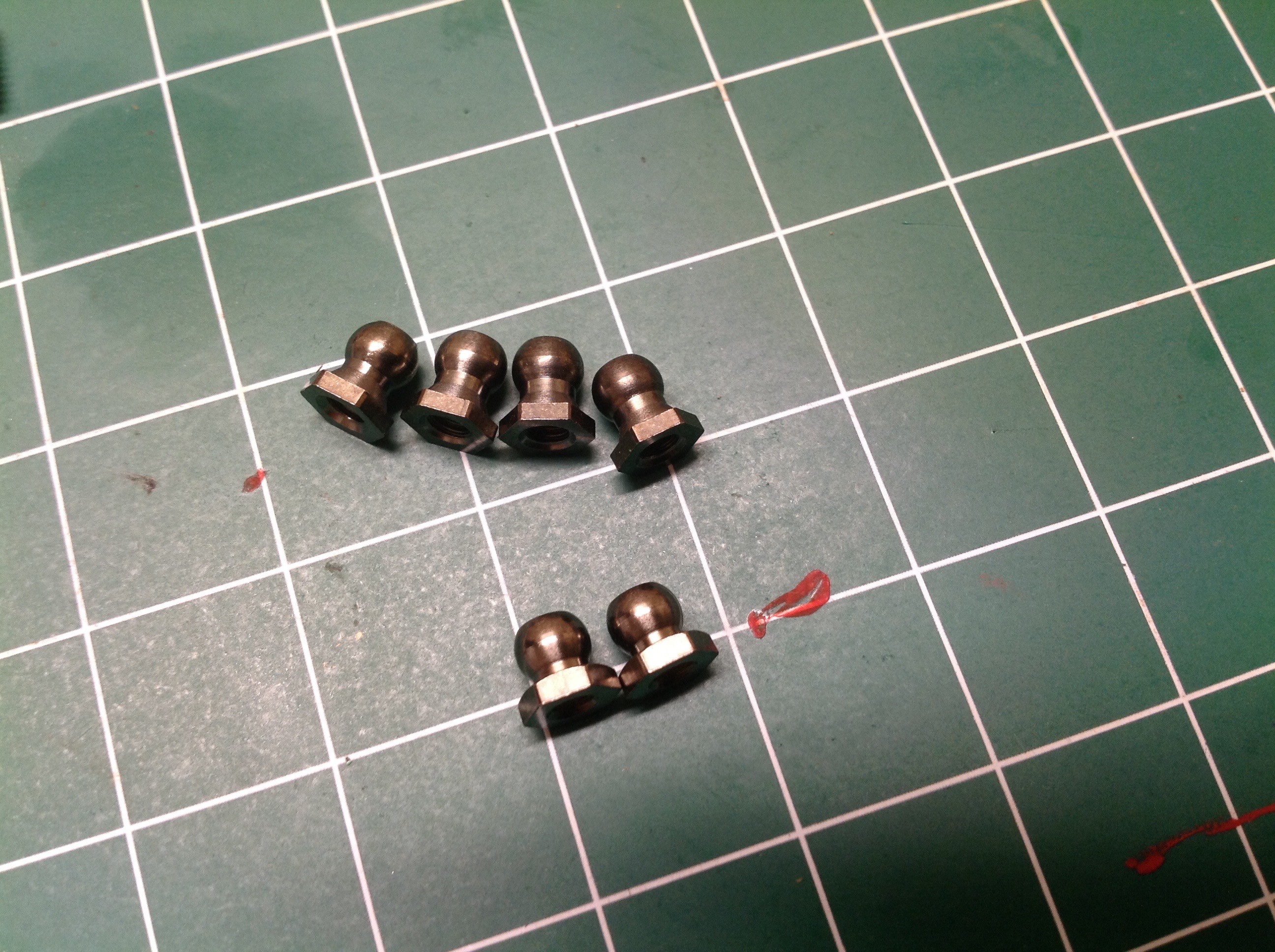
Did you notice that there are two sizes of ball joint here? I
didn't. They have different part numbers in the manual but it
still did not jump out at me that they were different. Make sure
you pay attention and use the two shorter ones in the right place.
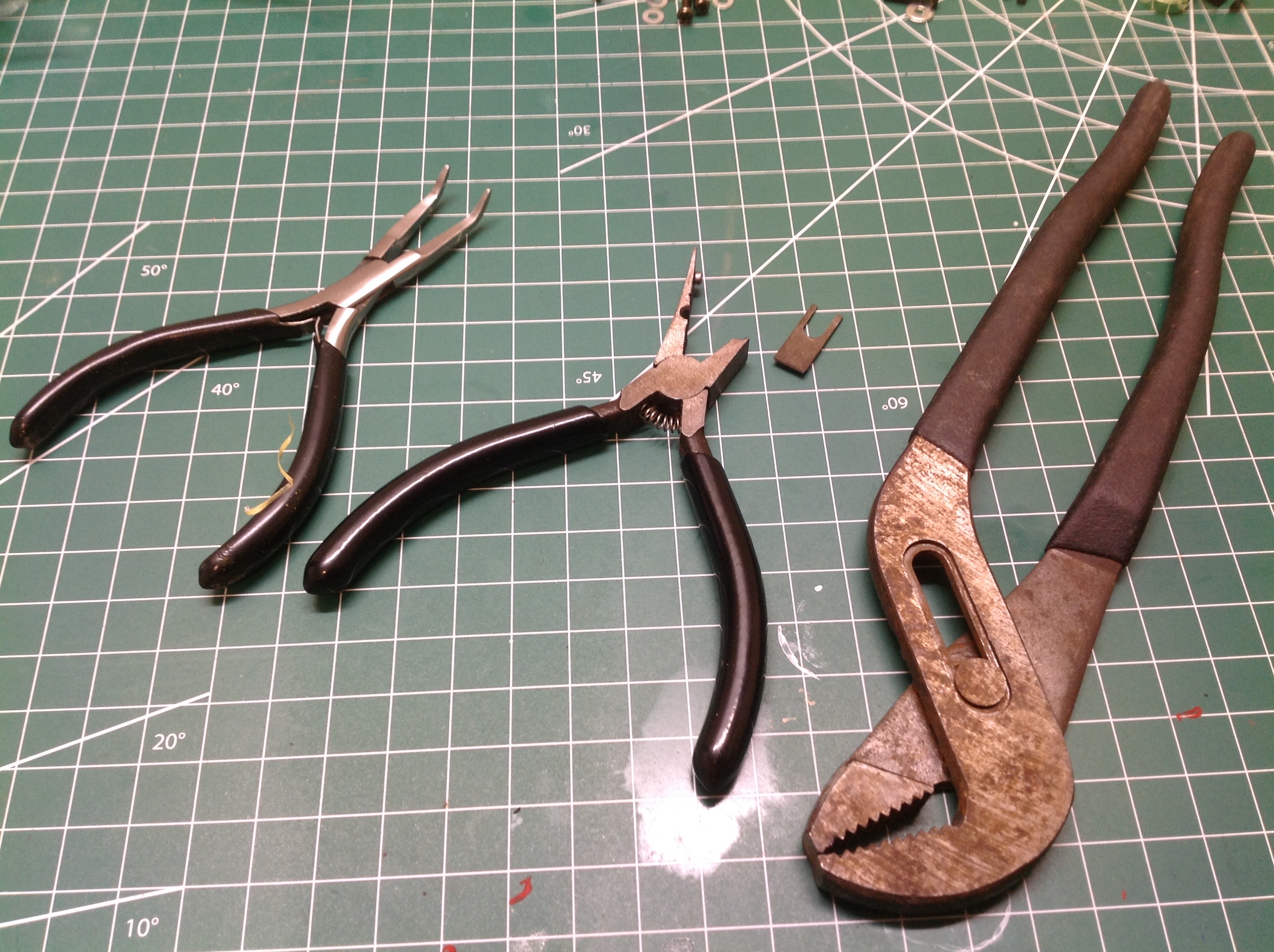
On the right you can see that I broke my ball joint pliers (center
tool), though I don't think it had anything to do with my failure to
distinguish between the two sizes. The fracture gave me the
opportunity to buy better tools which I do not lament.
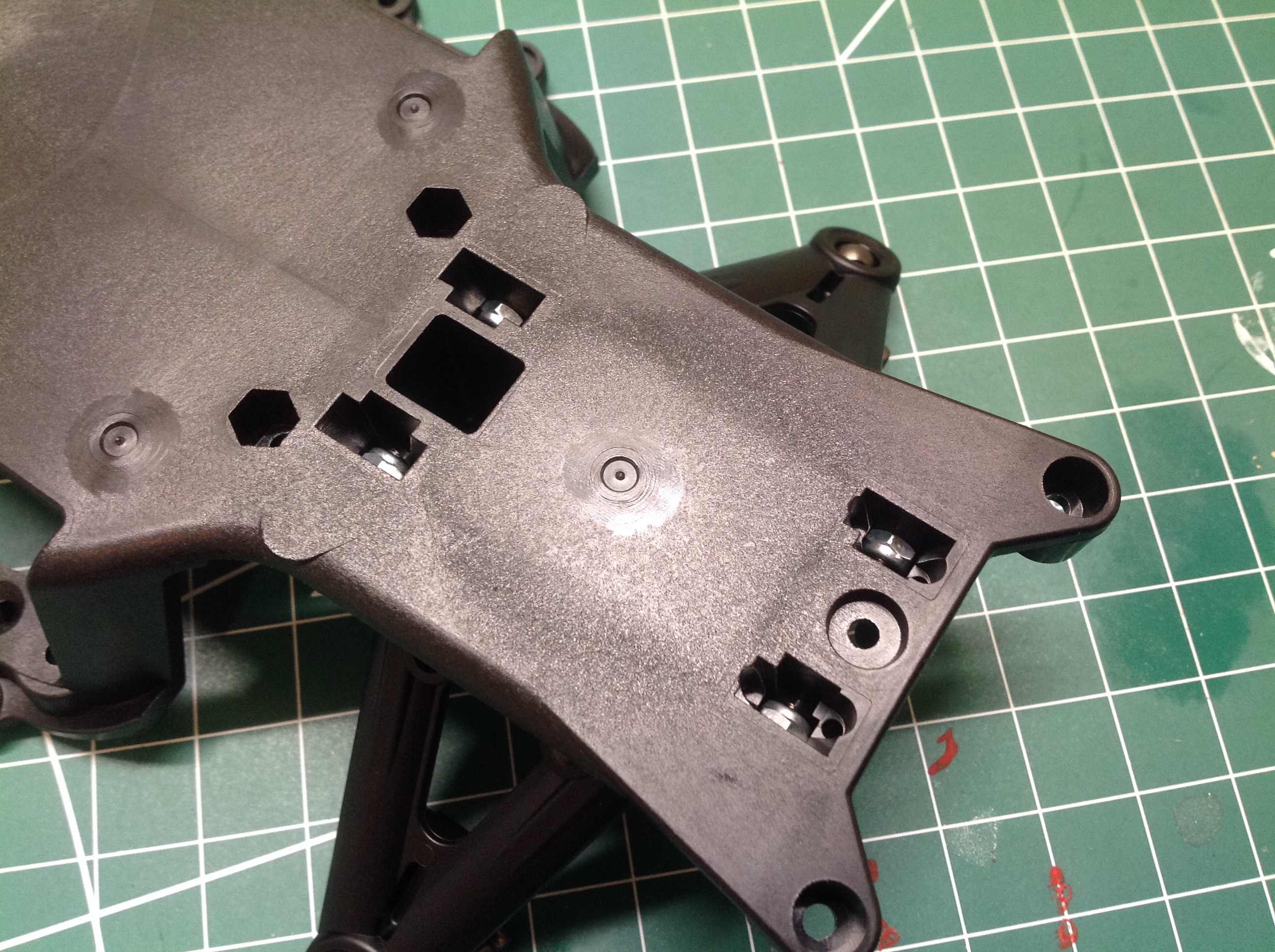
The build starts with the chassis tub and the fittings for the front
lower suspension arms. This models uses a lot of shims and spacers
to control part locations. The track width can be changed
slightly by altering the number and location of the washers shown on the
left. From what I can tell, pretty much every plastic part in
this model is glass filled so they should be pretty strong. It is
not a great idea to tap directly into GF plastic because it is
brittle. Tamiya got around this by using nuts almost
everywhere. On the right you cans see multiple slots for nuts
viewed from the bottom of the chassis. This kind of assembly is
tricky since they tend to fall out while trying to assemble the mating
part.
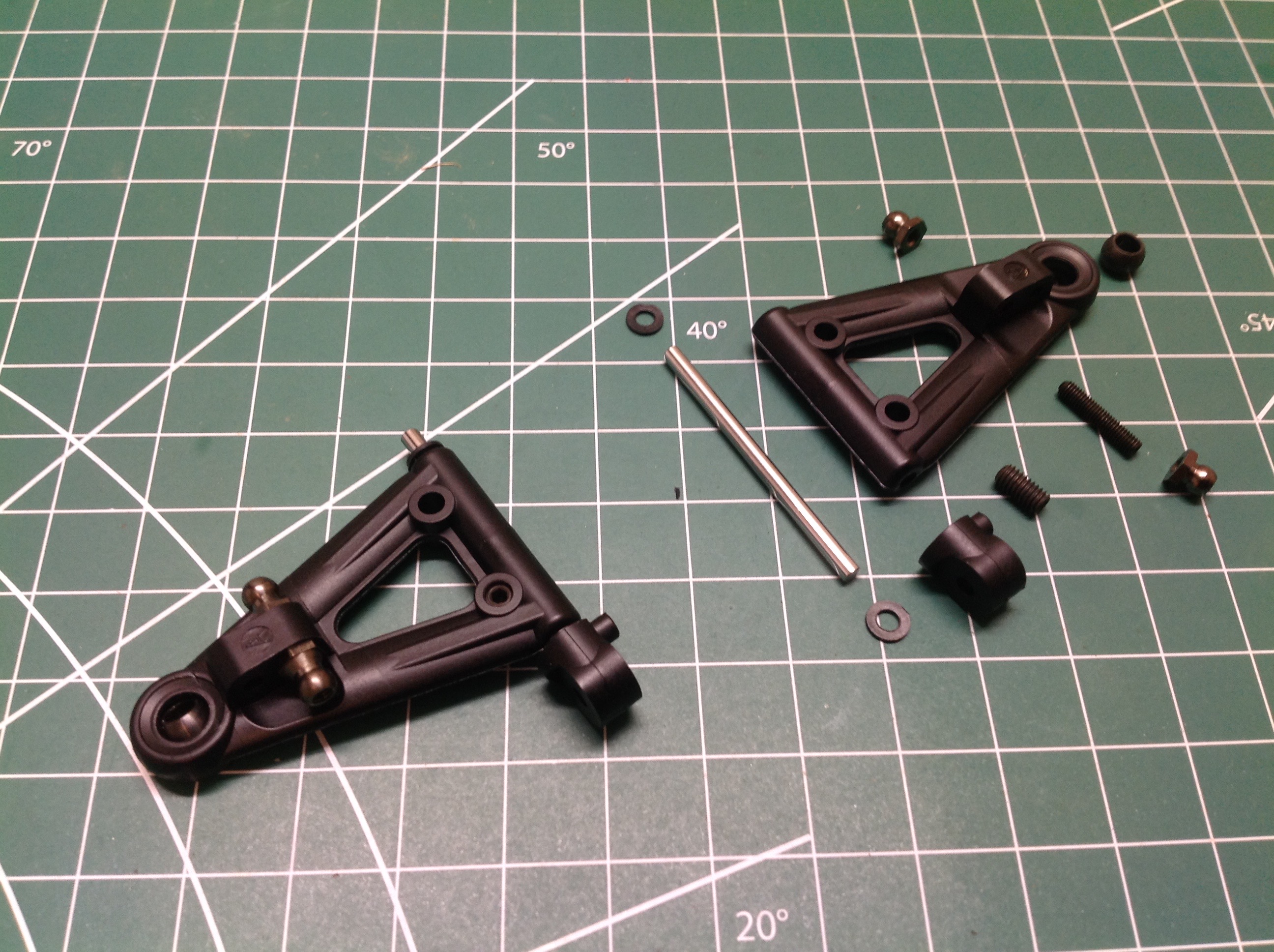
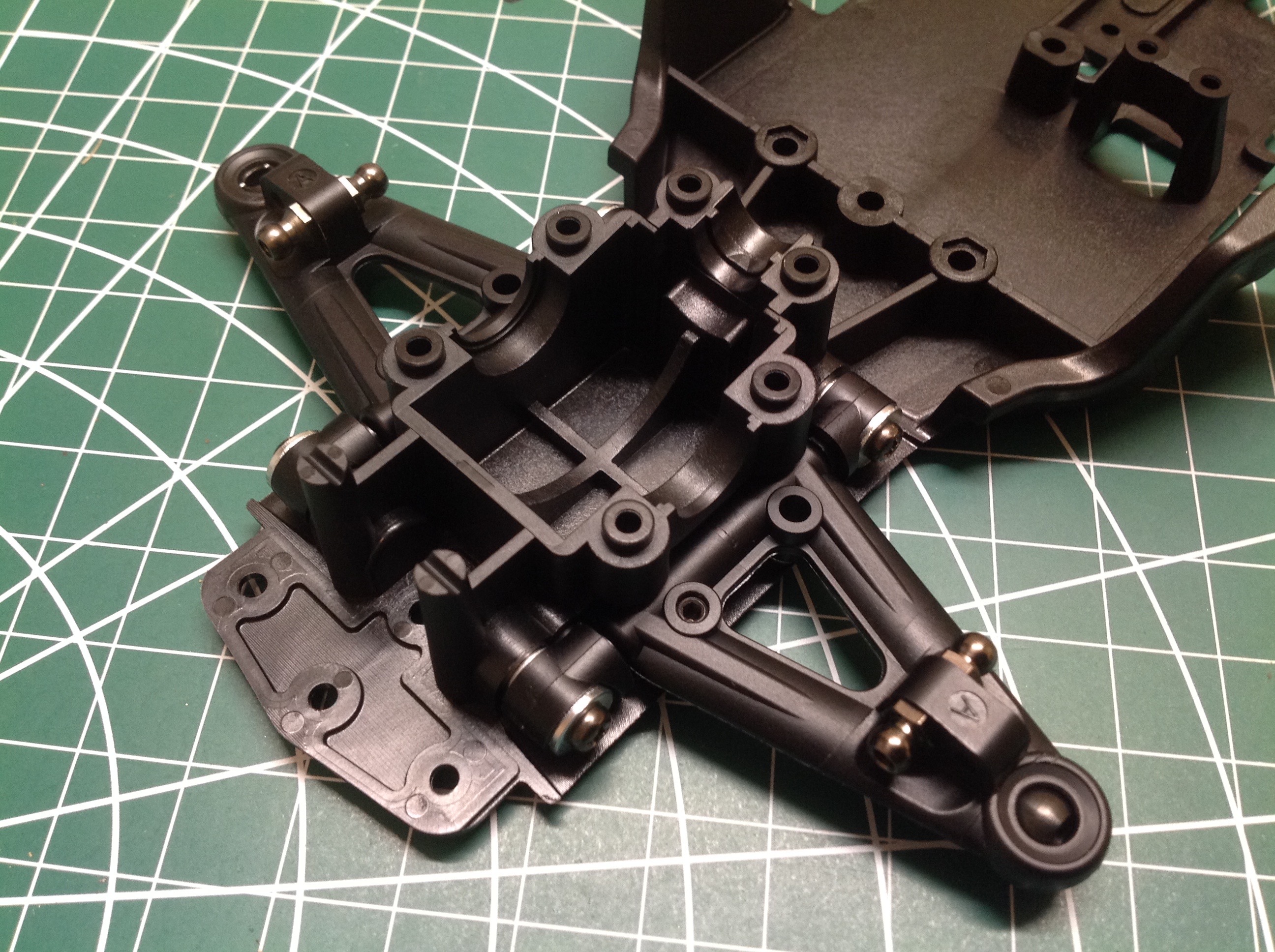
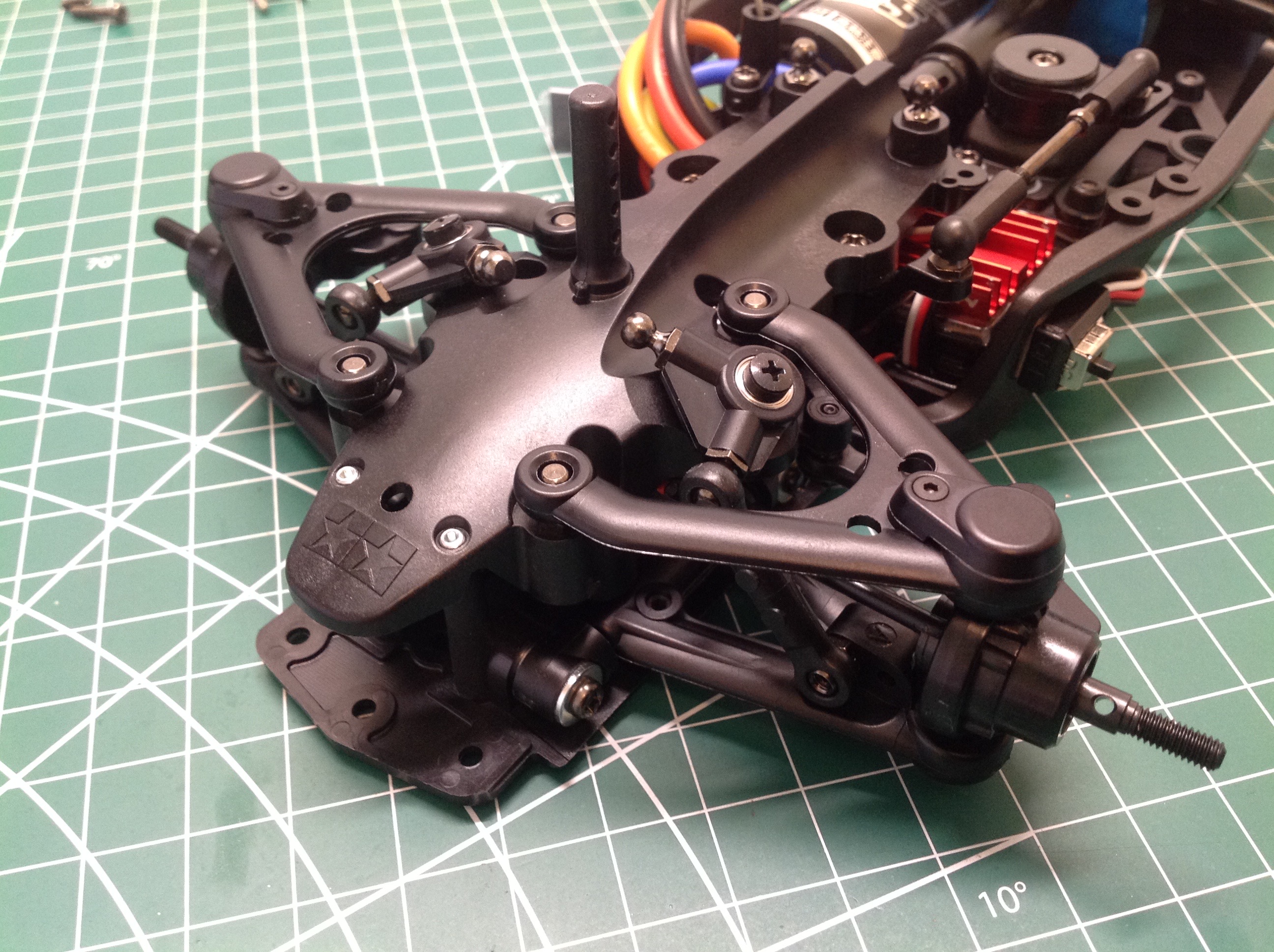
The lower wishbone arms assemble as shown in the exploded view.
The wheelbase can be adjusted using the shims which sit ahead and behind
the arms. A set screw which protrudes from the bottom acts as a
bump stop and sets ride height. A metal ball is pressed into the
end to support the uprights. The other two ball joints are for the
shock pushrod and the anti-sway bar. The rear suspension goes
together exactly the same way using the same parts. The rear toe
angle is also adjustable by differentially varying the number of washers
on the front and back arm mounts.
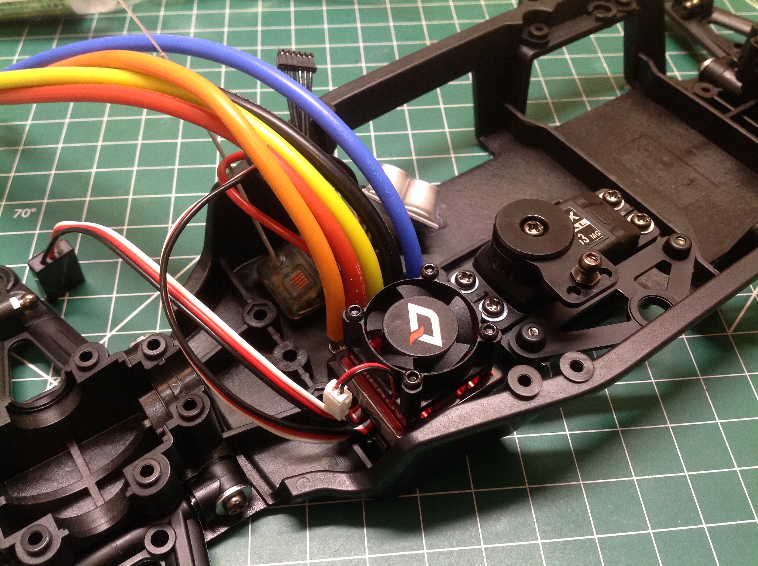
There is very little room for electronics in this model so your choices
are very important. A low profile steering servo must be
used. I've got a fast Savox racing servo here. The kit does
come with Tamiya's high torque servo saver which uses metal
springs. I'm pretty sure the bracket outboard of the servo is for a
transponder. I used the small Hobbywing ESC shown on the right,
but I had to later remove the cooling fan since it simply wouldn't
fit. They don't say so in the manual, but chances are that the
Tamiya TBLE-03s would be the best fit.
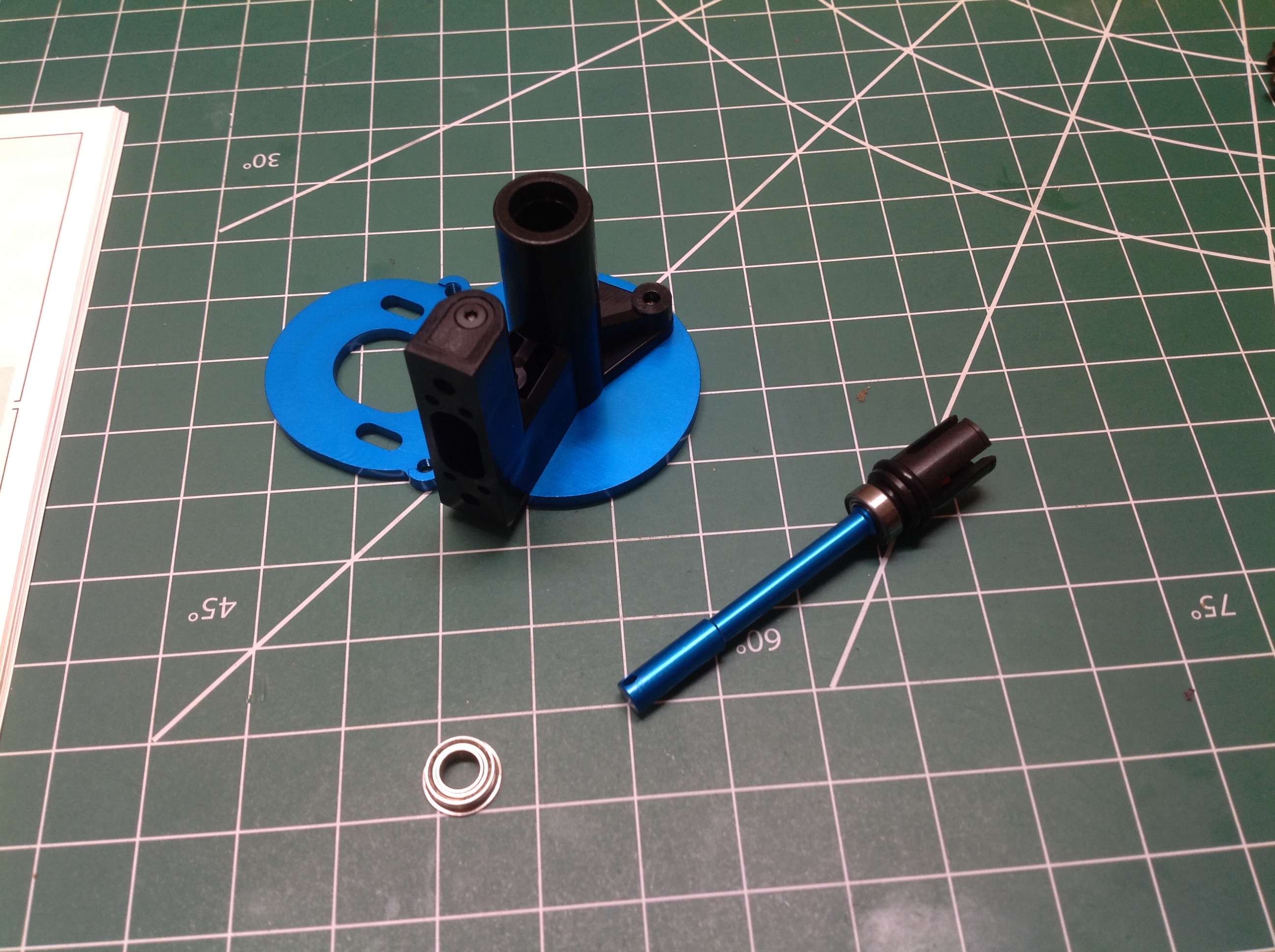
Time to get the motor mounted. The motor mount is an aluminum
plate supported by a plastic bracket which houses an aluminum main shaft
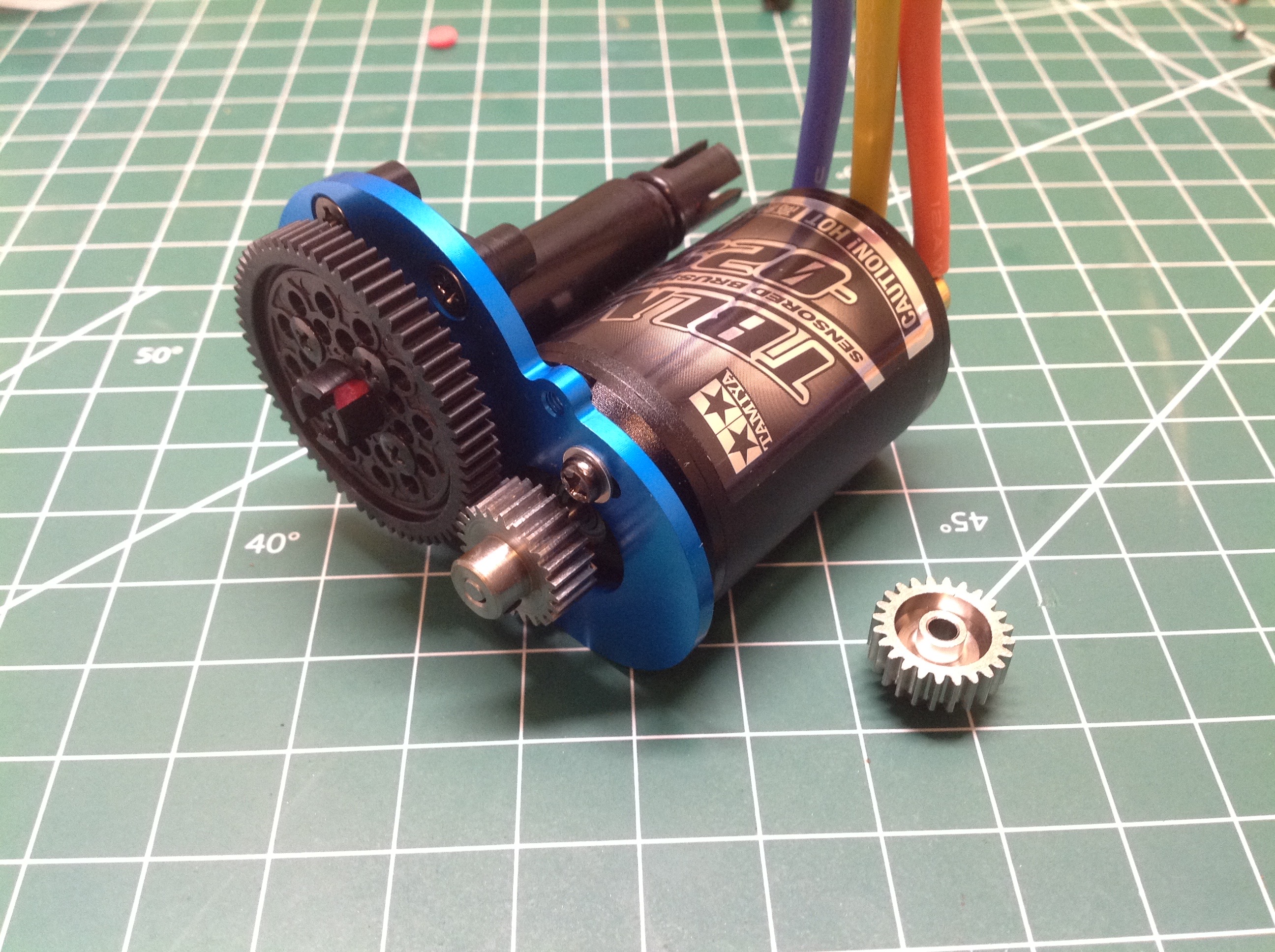
supported by included ball bearings. I used a 10.5T Tamiya
TBLM-02s sensored brushless motor which is about as powerful as you
would want to put in this chassis. I replaced the stock 24T
aluminum pinion with a steel version from Robinson Racing as
shown. The spur is 63T and does not use a slipper clutch.
Gear pitch is 0.6 mod (metric). The stock ratio is 6.56:1 but can
be adjusted anywhere from 5.25:1 to 7.5:1 using pinions from 21T to
30T. No optional spurs are listed because everything is so tight I
don't think anything else would fit.
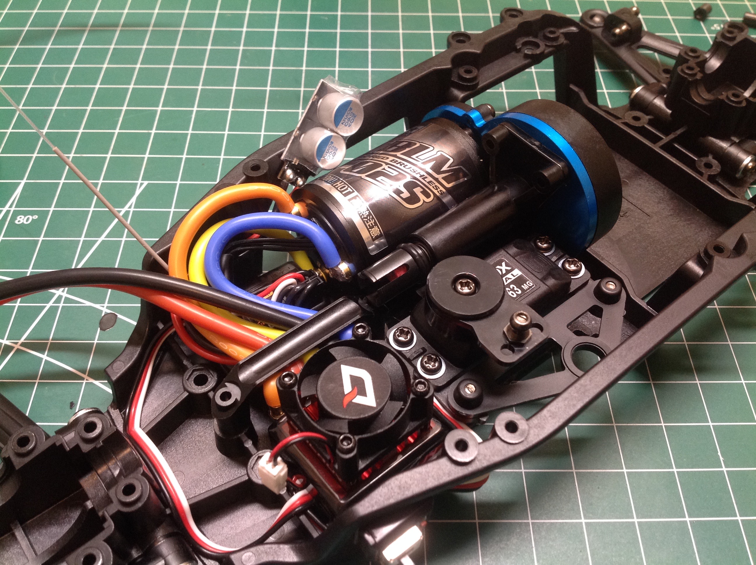
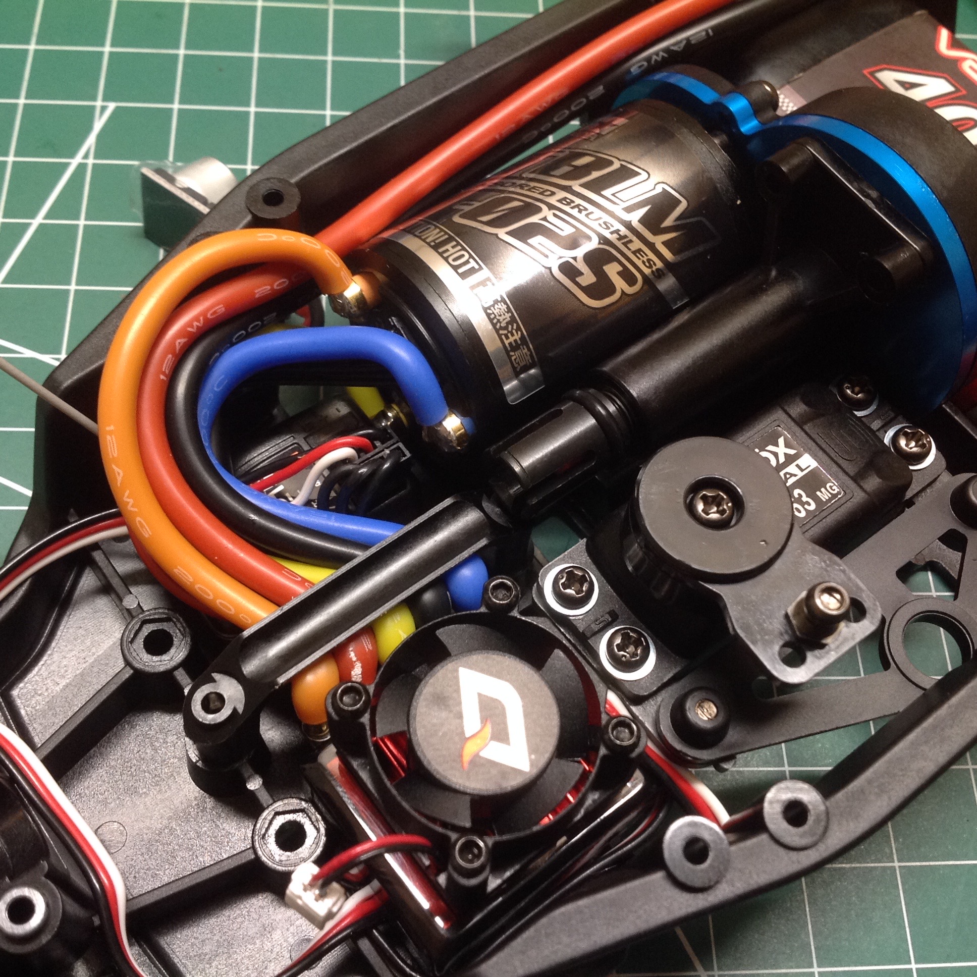
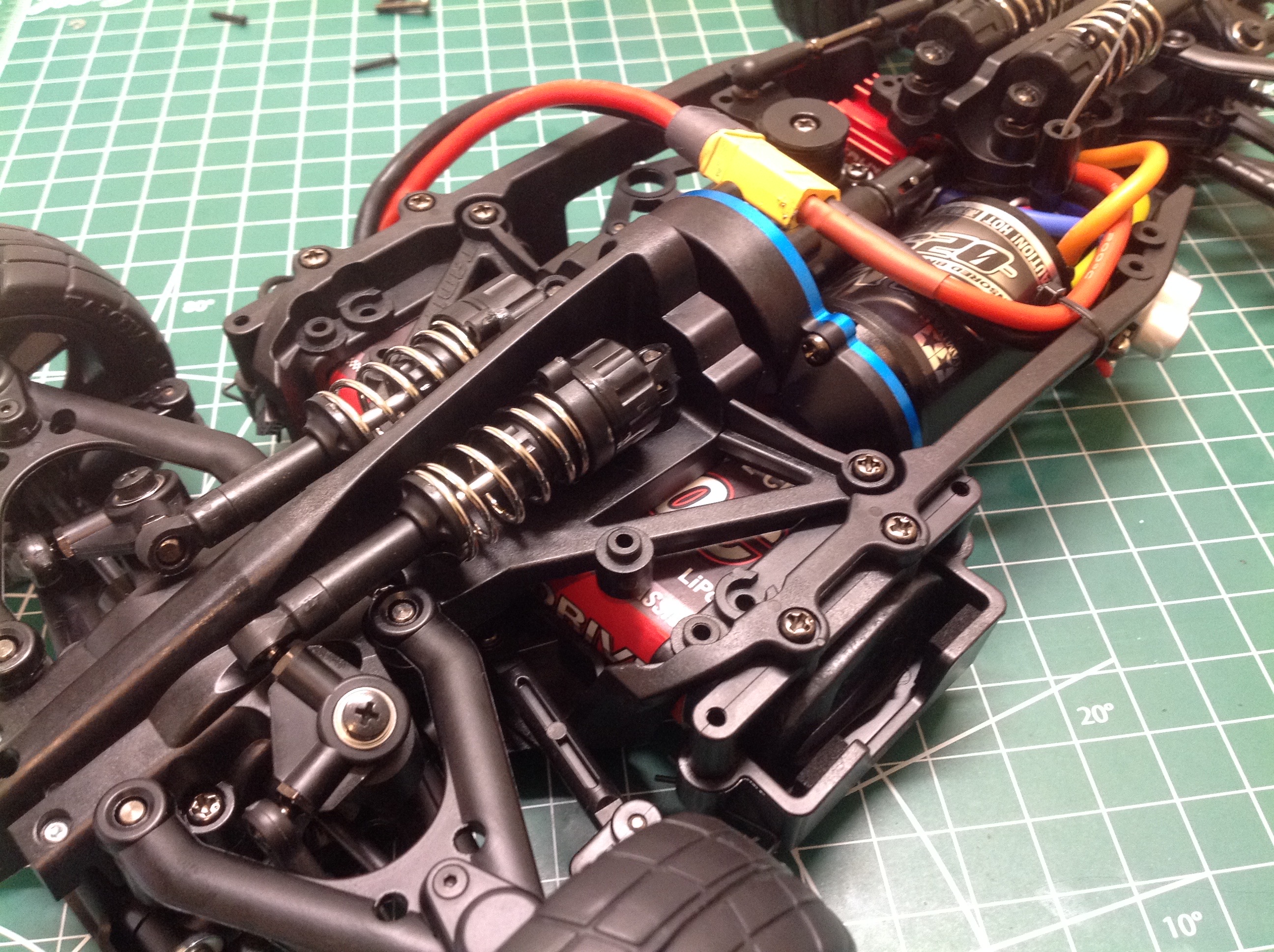
Now I'm trying to cram all those electronics into the chassis. The
Tamiya TBLM motors don't use solder tabs, they use bullet connectors
inserted into the end. I trimmed all the wires to length and
soldered them to the connectors as shown. A bracket then mashes
all the wires down against the chassis because the front drive shaft
will sit right above and needs to be clear of obstacles. On the
right you can see that I've also hidden the motor wires as much as
possible. My ESC came with a capacitor pack for which it was hard
to find a home. I ended up sticking it to the outside of the
chassis, but still within the body lines.
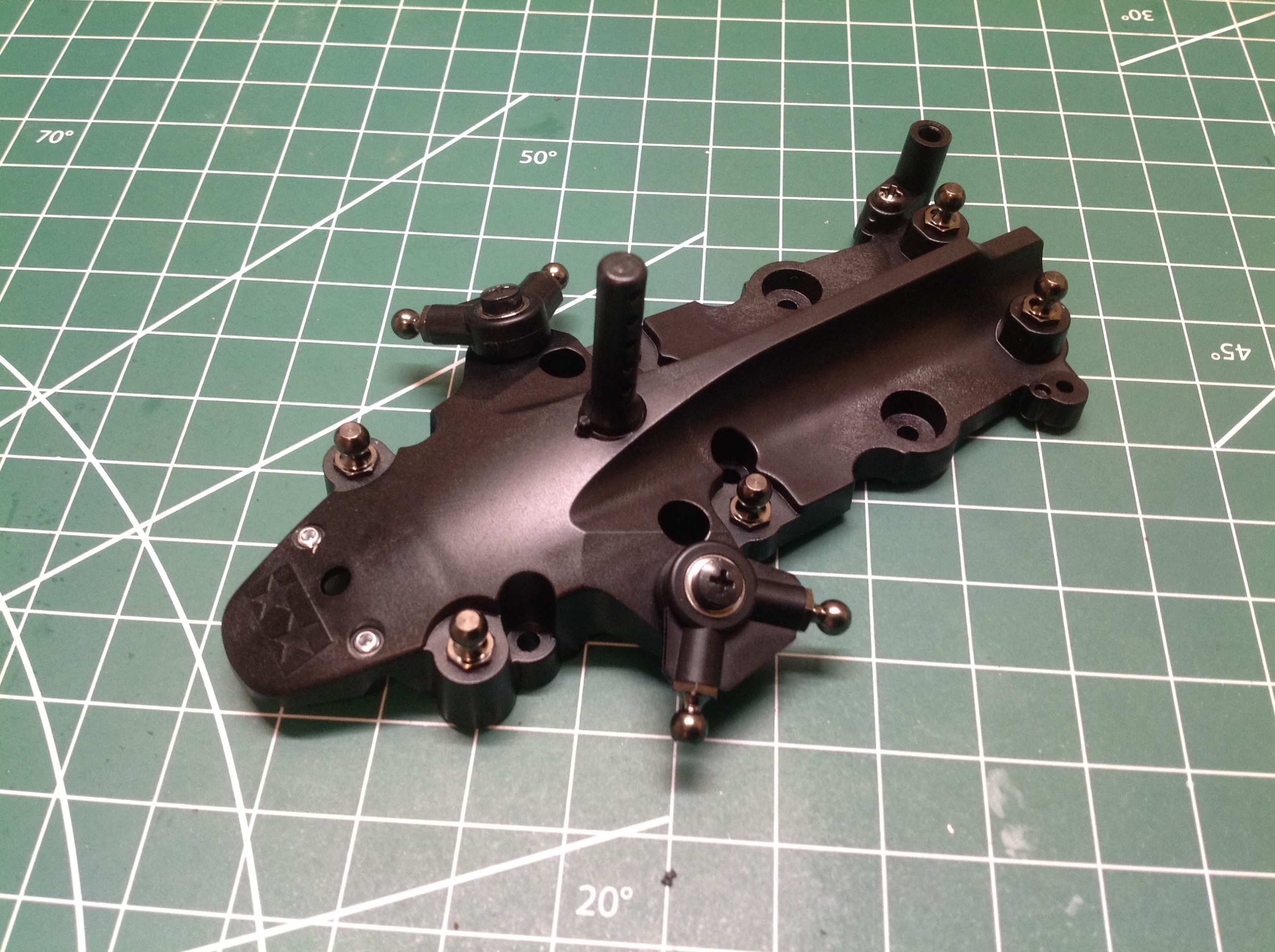
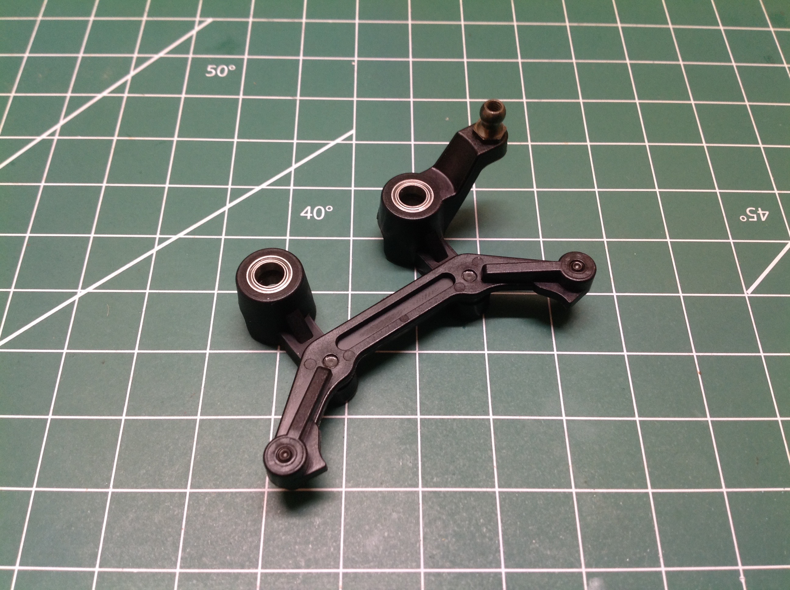
Time to start working on the suspension. The front cover is
assembled by adding 90° crank arms to it supported by ball
bearings. The other 6 ball joints seen will be for the upper arms
and shocks. There are a lot of ball joints on this
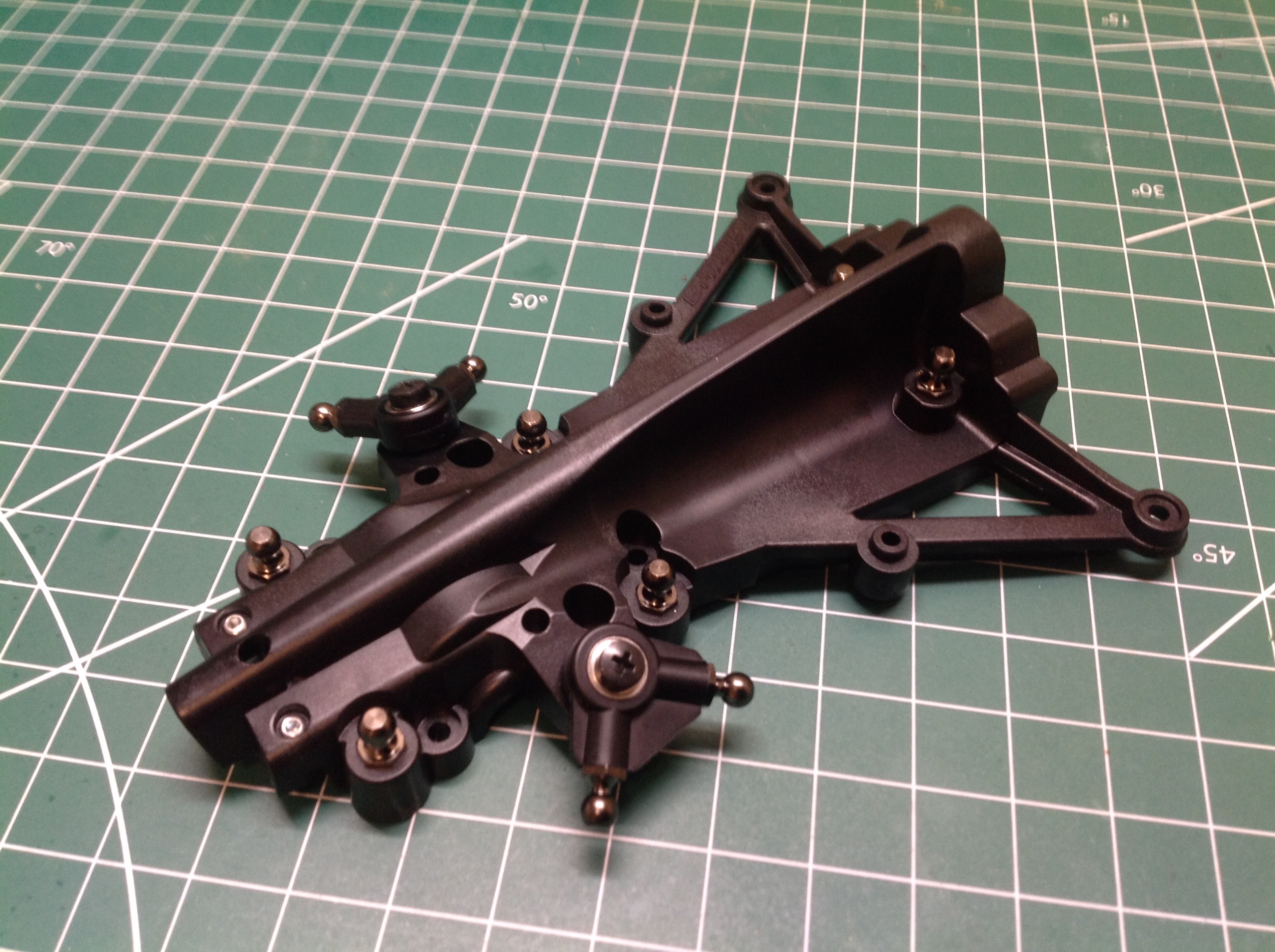
model. The rear cover is shown on the right and works exactly like
the front though the outer profile is a bit different. These
covers will enclose the differentials.
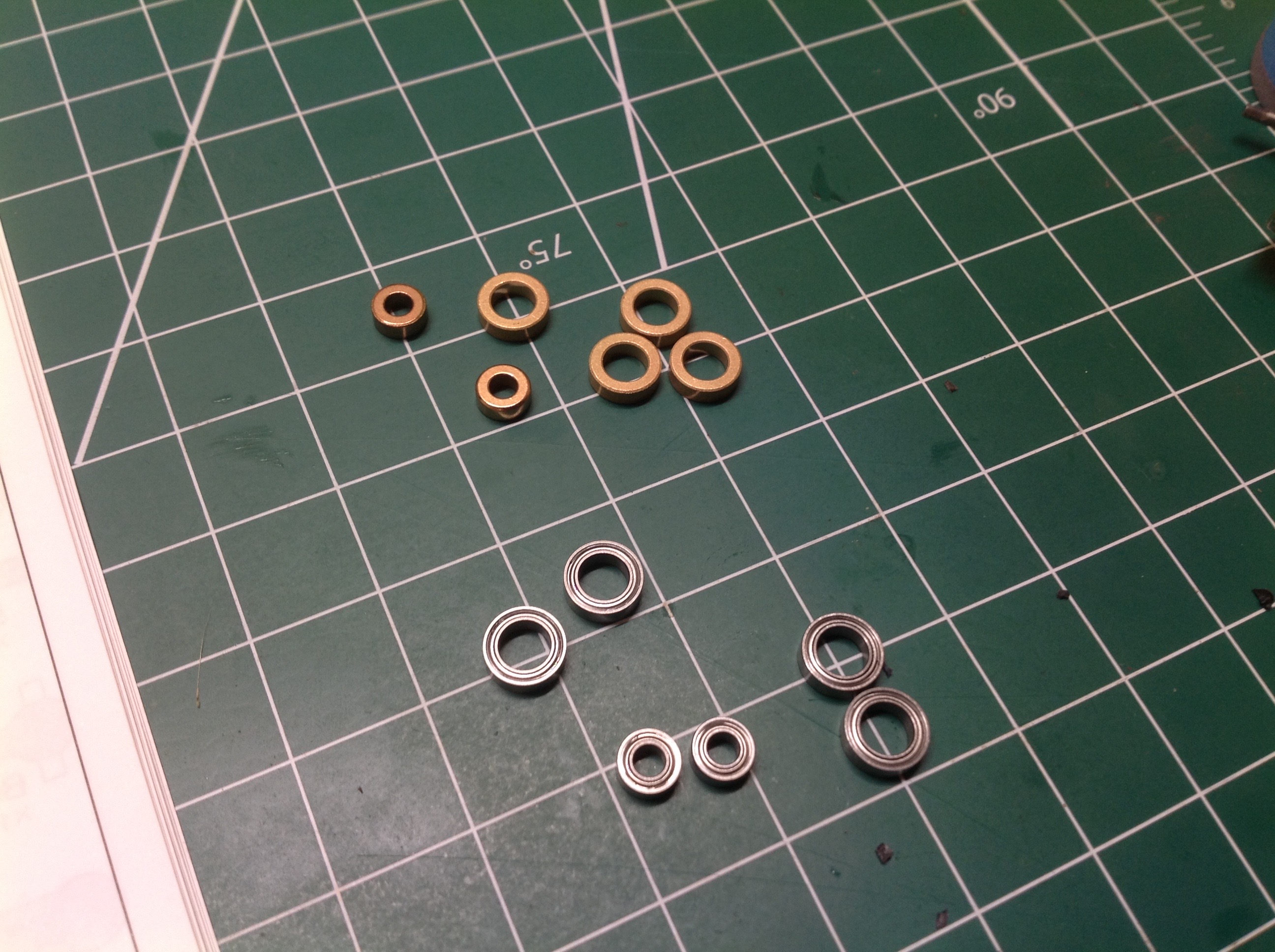
This picture shows the only metal bushings which came with the model and
these are intended to be used for the steering mechanism.
Bushings can arguably provide tighter action than bearings because there
are fewer clearances, but I switched to bearings anyway.
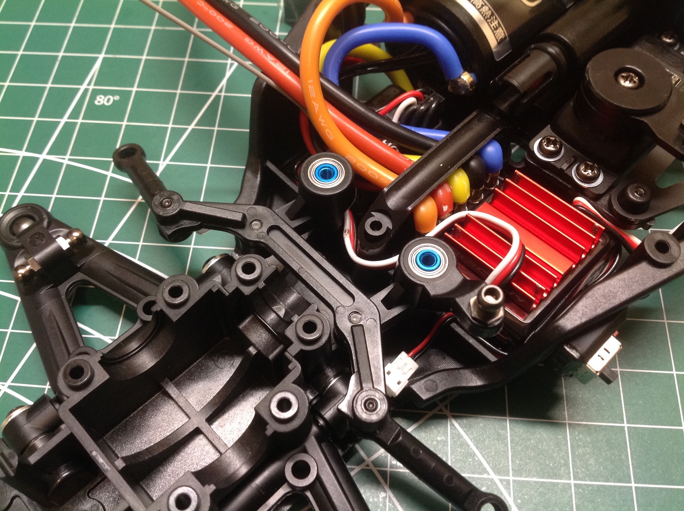
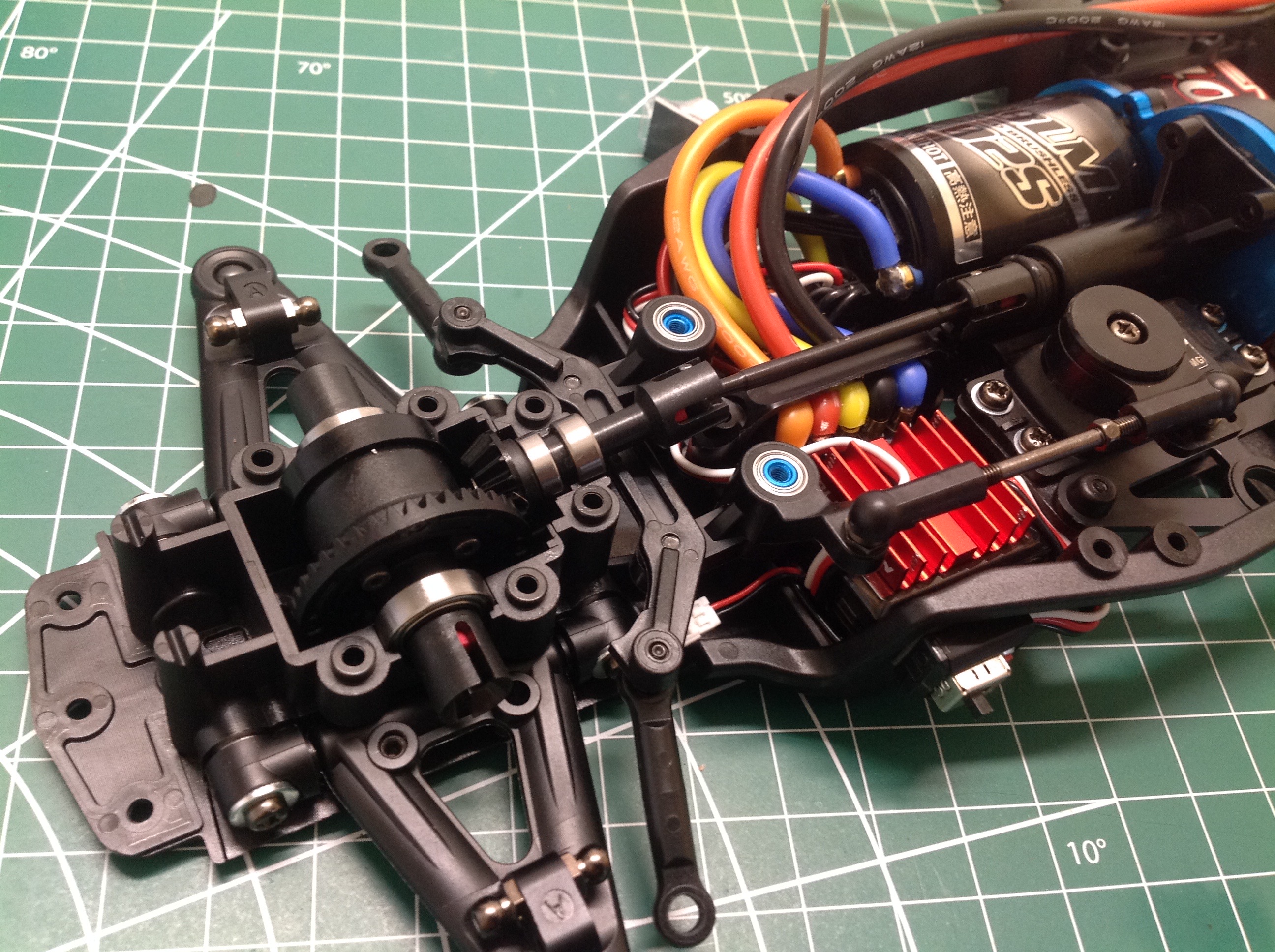
Here the steering linkages have been installed and you can see how little
clearance they have to adjacent wires. Wire routing and tie downs
are very important on this model. The steering rods are intended
to be fixed length, though spacers can be added to adjust the toe angle.
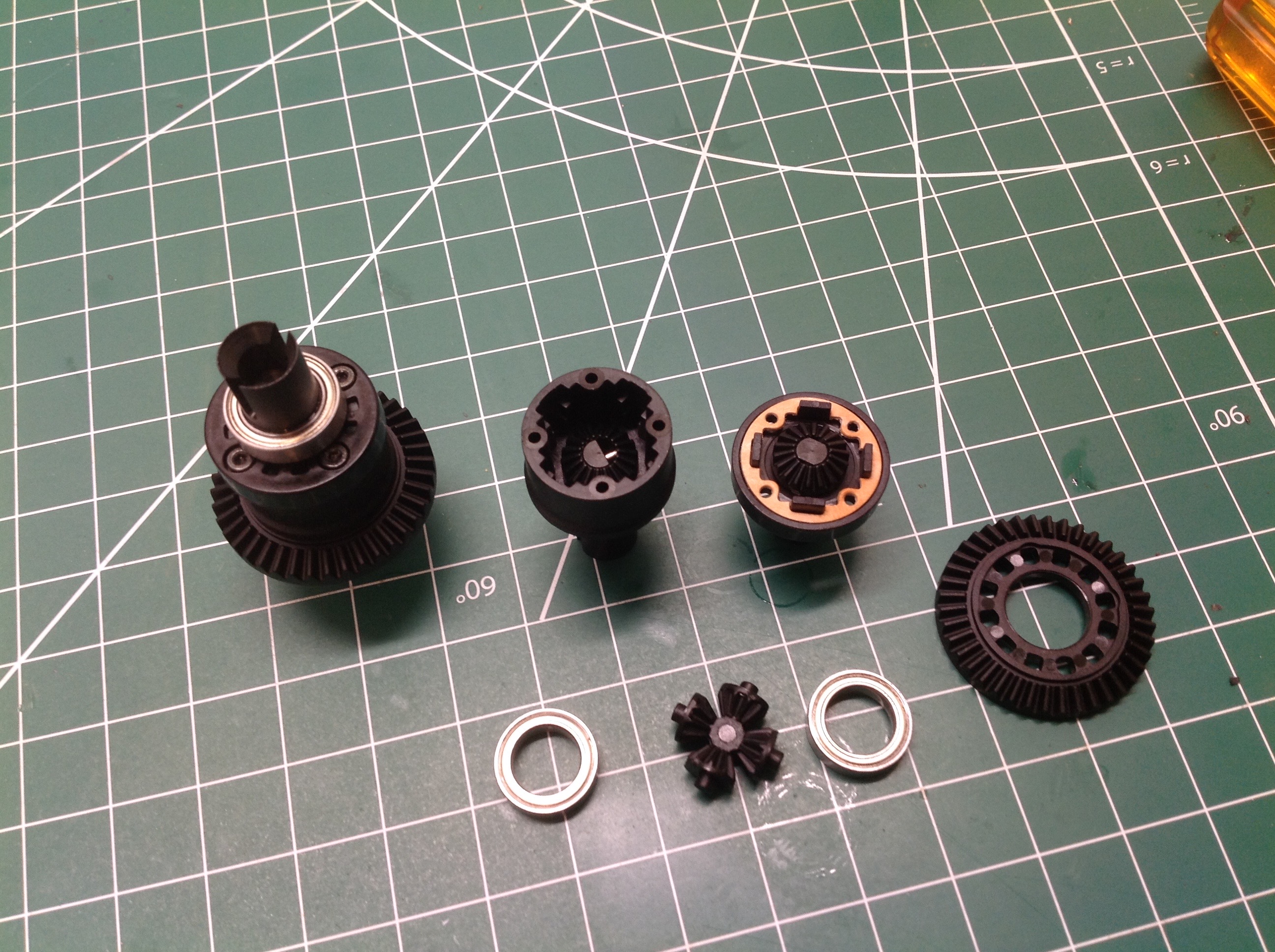
The front and rear differentials are identical so two are built at this
point. The diffs are open but oil filled so resistance can be
adjusted by using different viscosity oils. Tamiya clear shock oil
comes with the kit and is used to fill the diffs. The internal
spider gears are plastic as is the cross bar. Steel optional parts
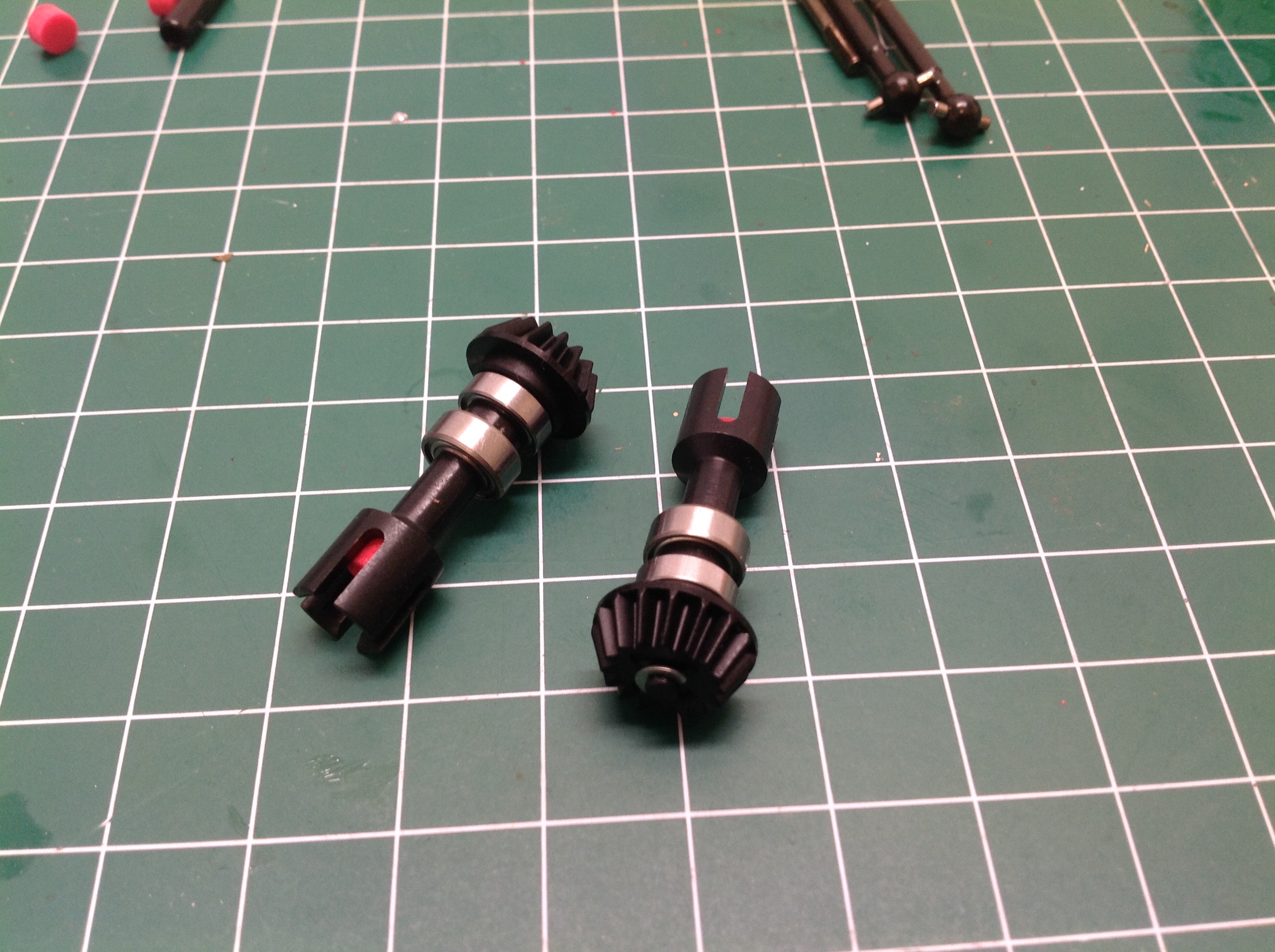
are available. The differential pinion gears are shown on the
right.
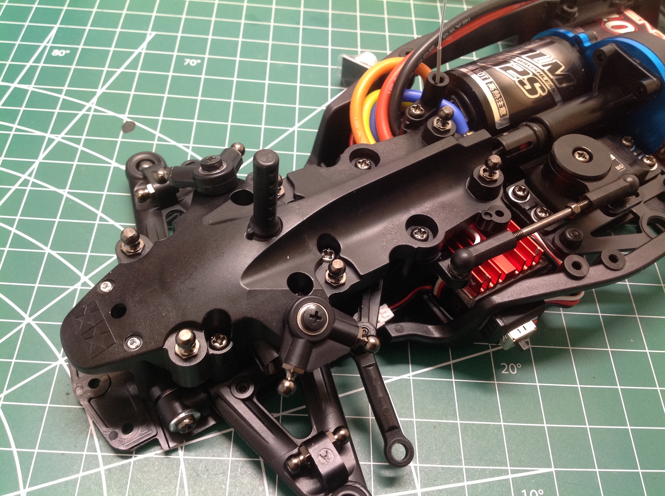
Here you see the installation of the front driveline. The
differential is installed into the chassis along with the front drive
shaft. You can see that there is an angle between the shaft and
the drive cup which is not ideal for efficiency. These can be
replaced with universals. Once the gears are greased, the front
cover can be installed which completely obscures the steering
linkage. You can see how little clearance there is above the ESC.
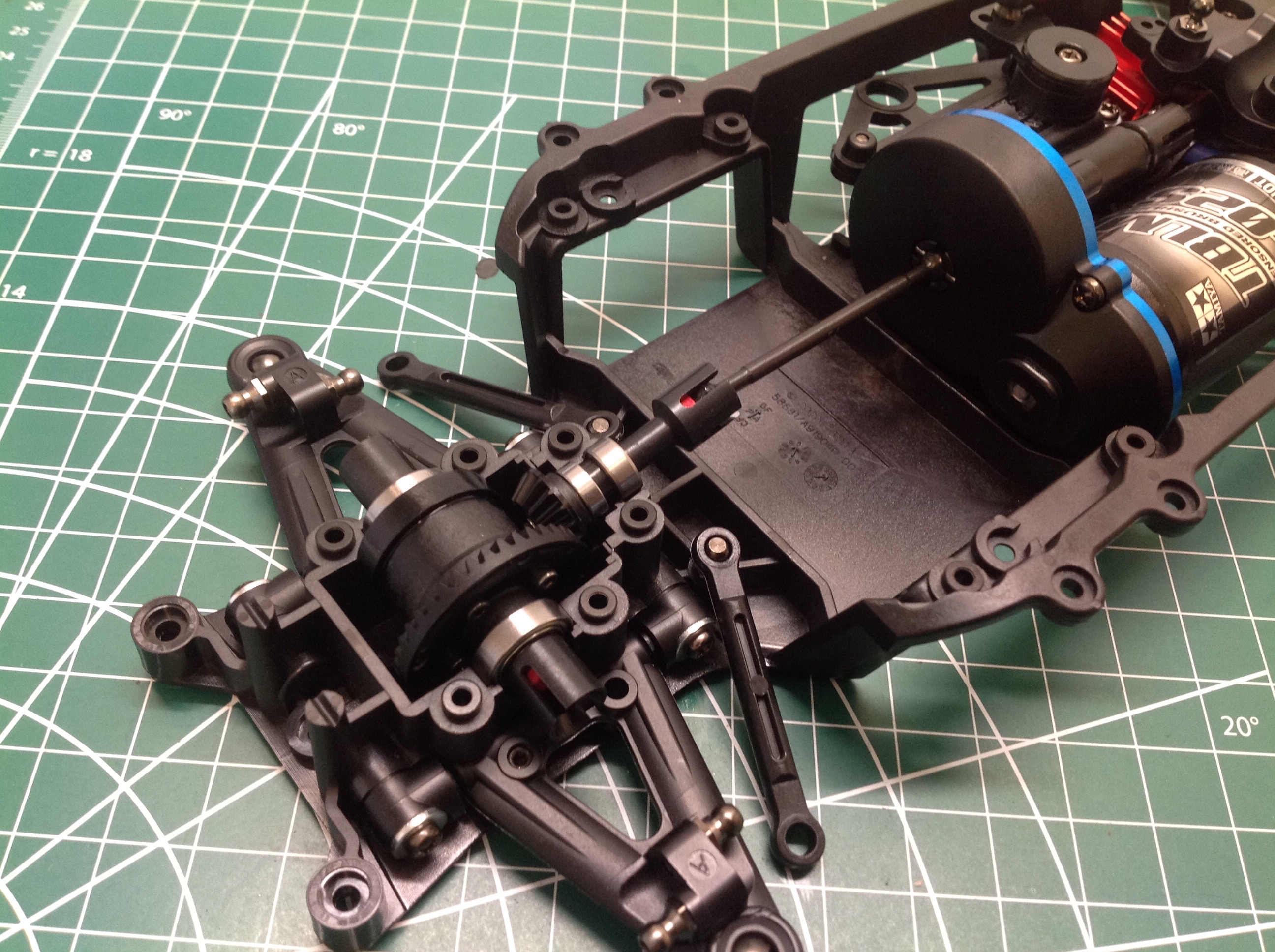
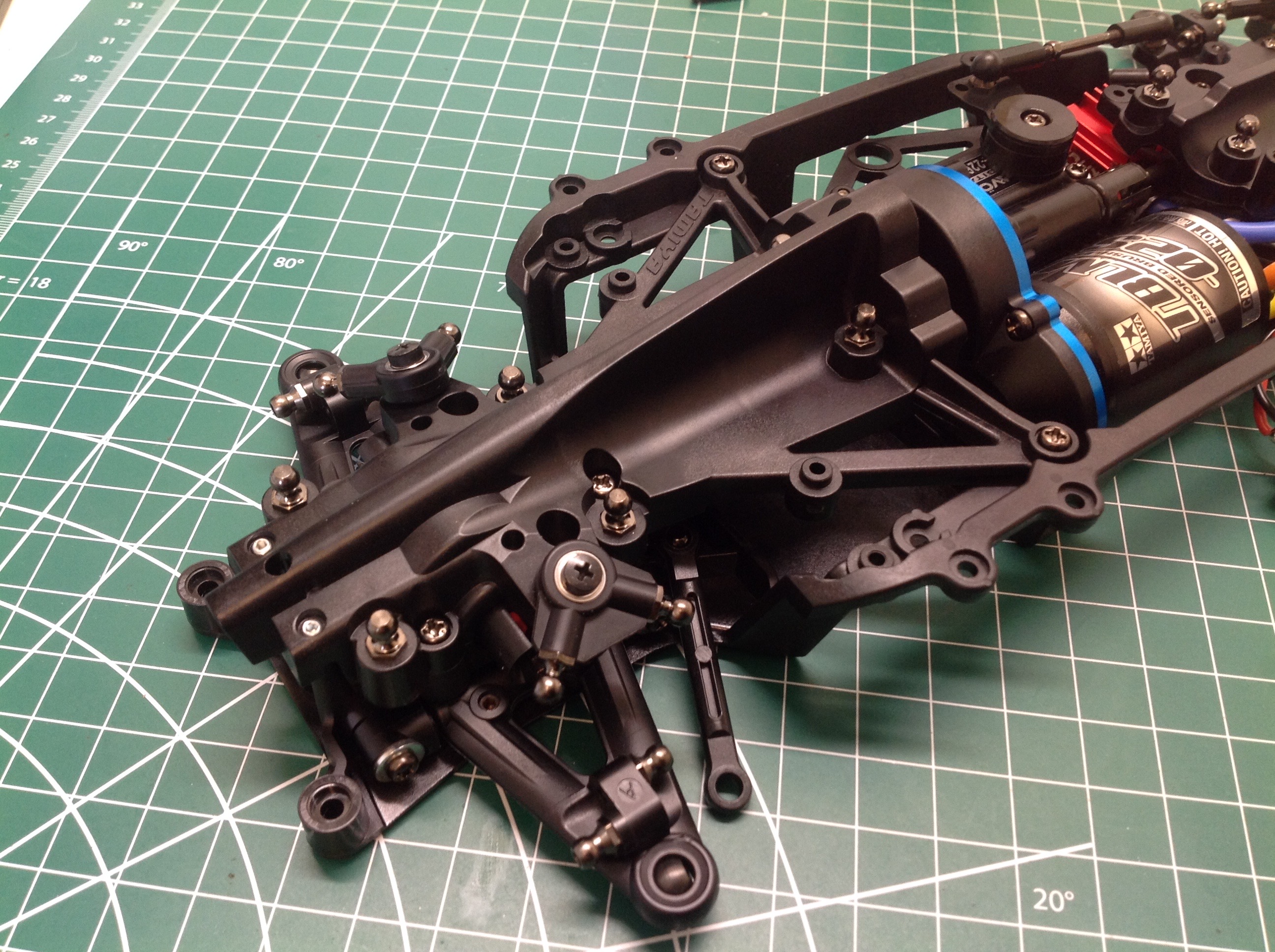
The back driveline installation works exactly like the front. The
battery will sit laterally in that slot underneath. The rear toe
angle is controlled by the fixed length links shown.
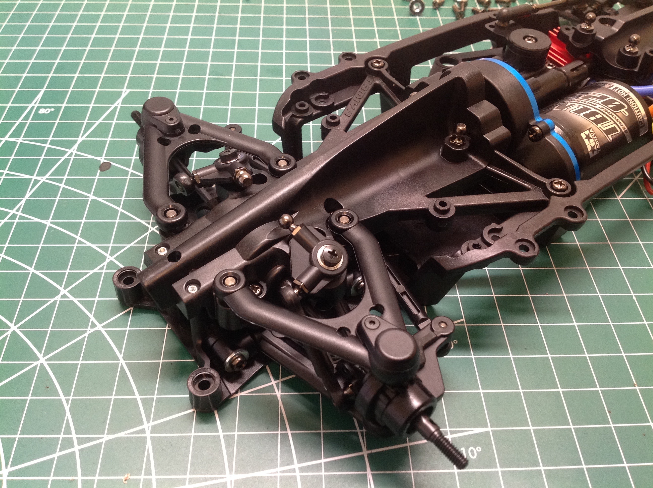
The upper suspension arms are true wishbones with ball joints at all
three corners. Plastic caps are installed on top of the outer
joints to prevent from being contaminated on the track. The same
arms and uprights are used in the front and back, but of course the rear
steering angle is fixed. The stubby pushrods for the shocks have
also been installed at this point connecting the lower arms to the
cranks. The outdrives are dogbone type.
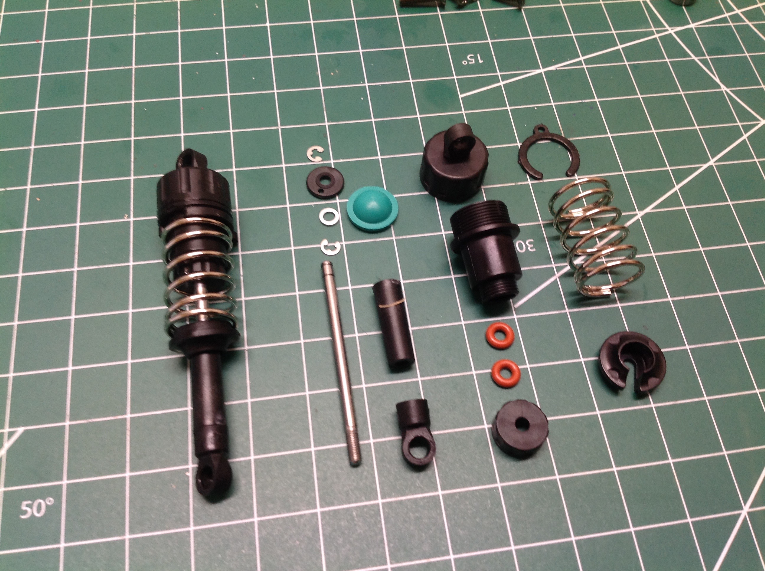
Now we'll build the unusual oil shocks. The assembly sequence
isn't odd, but the very short stroke combined with the very long rod
ends makes these look really odd. The springs are quite stiff
which makes sense with that short stroke. These inboard, pushrod
type shocks allow for a very low body. At the time I was
building, no aluminum upgrade shocks were available. The exploded
view on the left shows how the shocks are assembled and the view on the
right shows them all installed. The shocks are filled with the
same fluid used in the differentials, Tamiya's second heaviest weight.
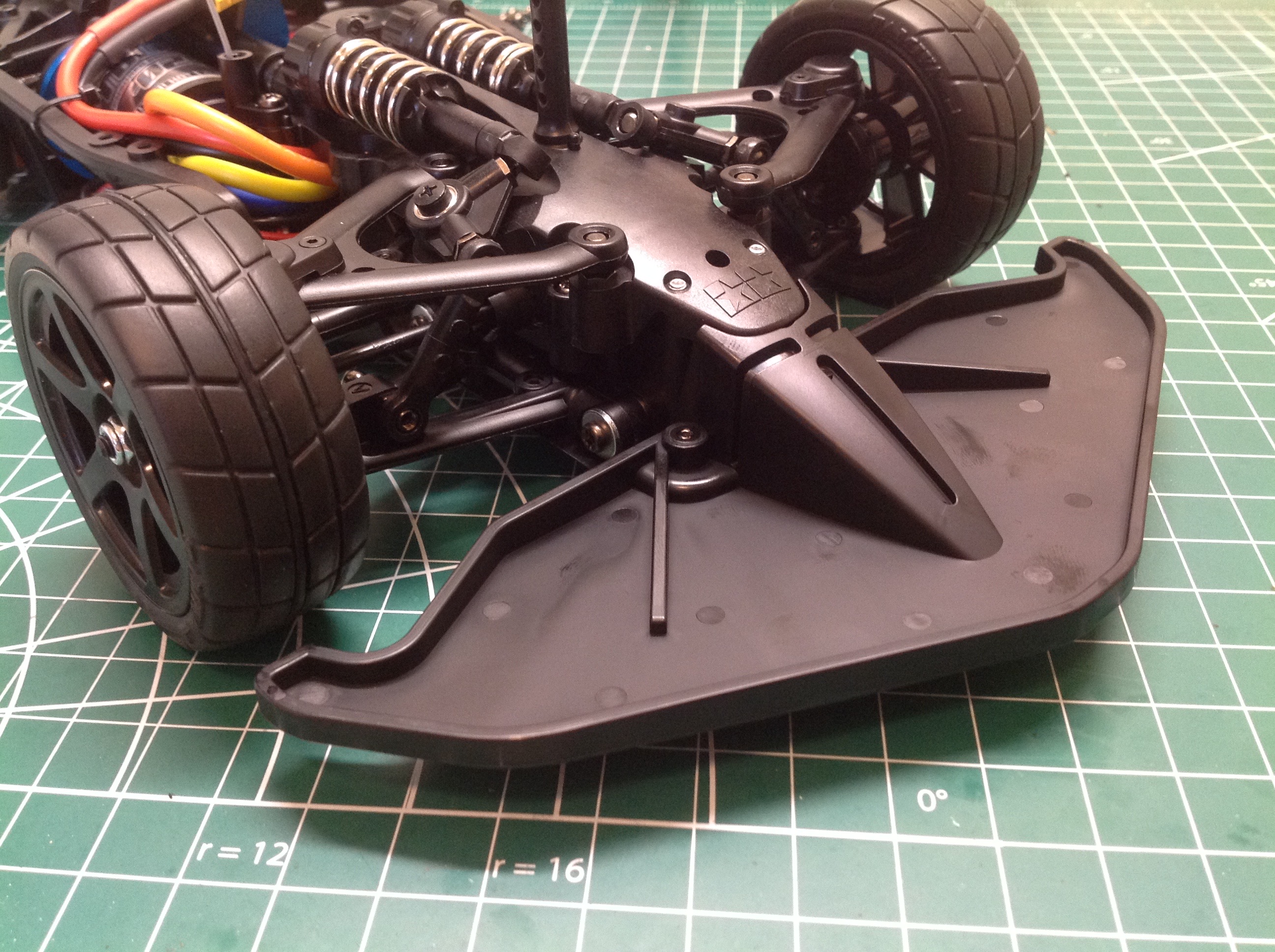
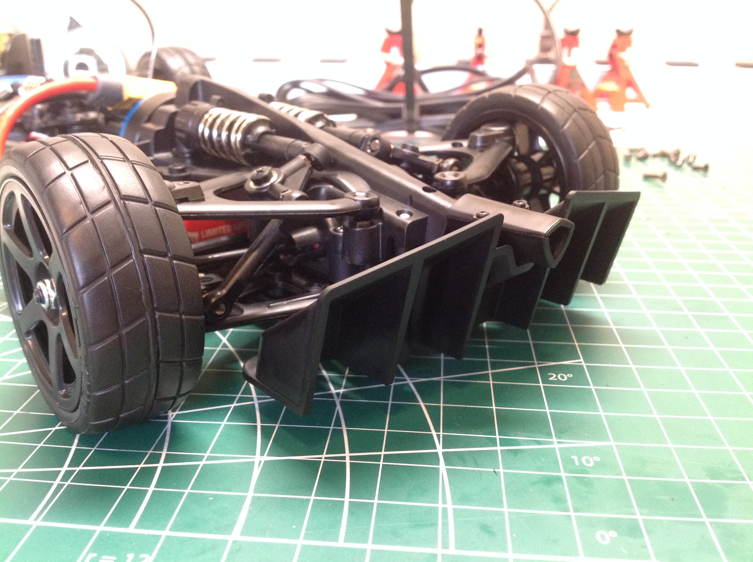
The kit includes plastic wheels and directional tires with foams. The tires must
be glued or they will come off immediately. These photos show the
wheels and tires as well as the aerodynamic aids in the front and
rear. There is a huge splitter in front which also serves to
protect the fragile body and a diffuser in back.
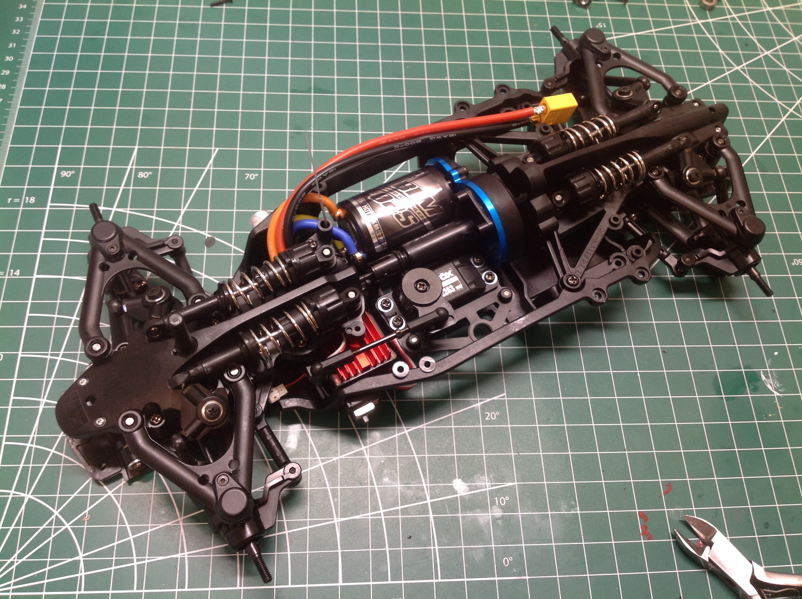
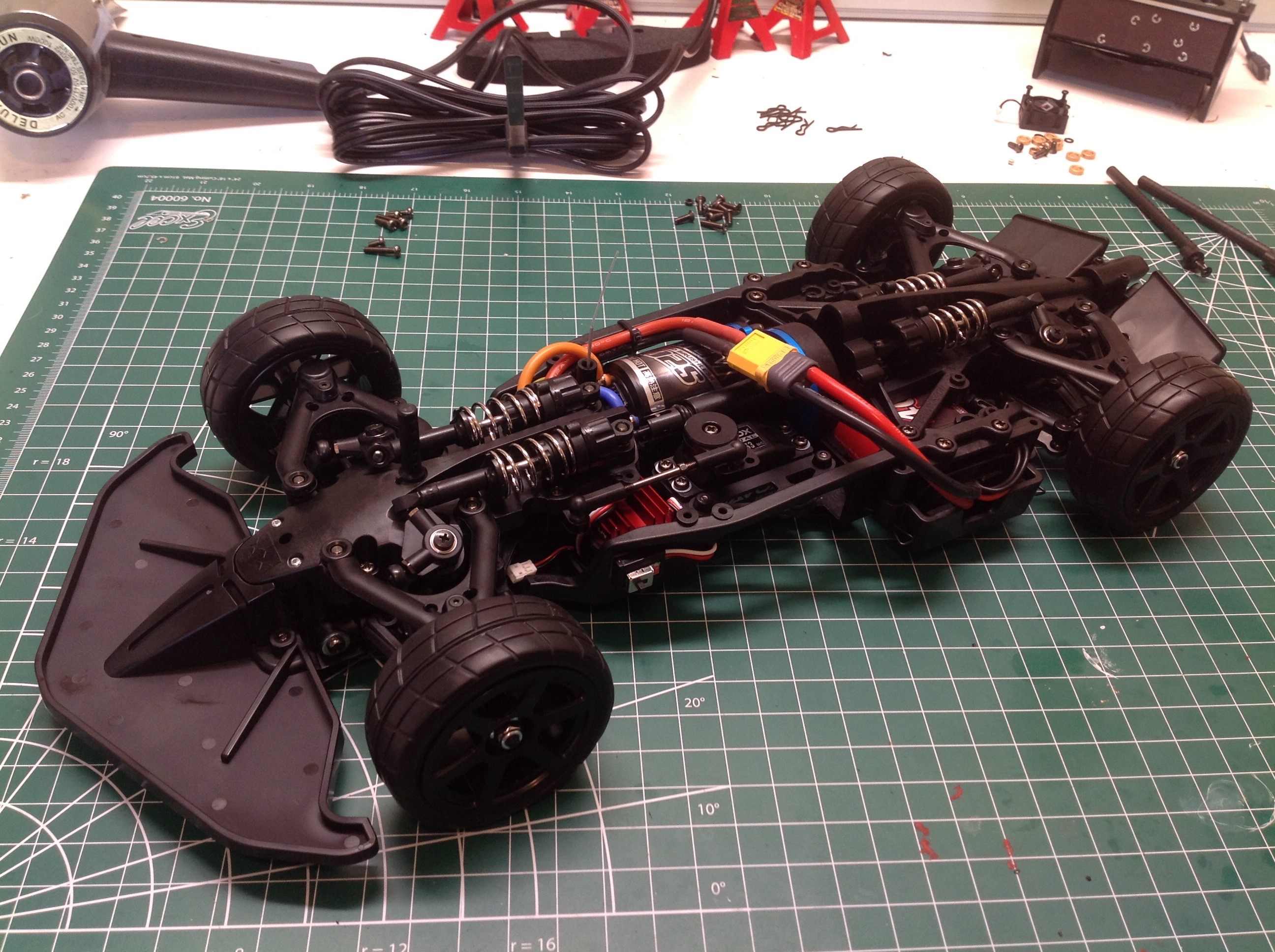
Here is the completed chassis. It is completely driveable at this
point. I had no trouble fitting my standard 2s LiPo in this
chassis as shown.
©2021 Eric Albrecht