Tamiya TRF201 Project
Page 1: Building the TRF201
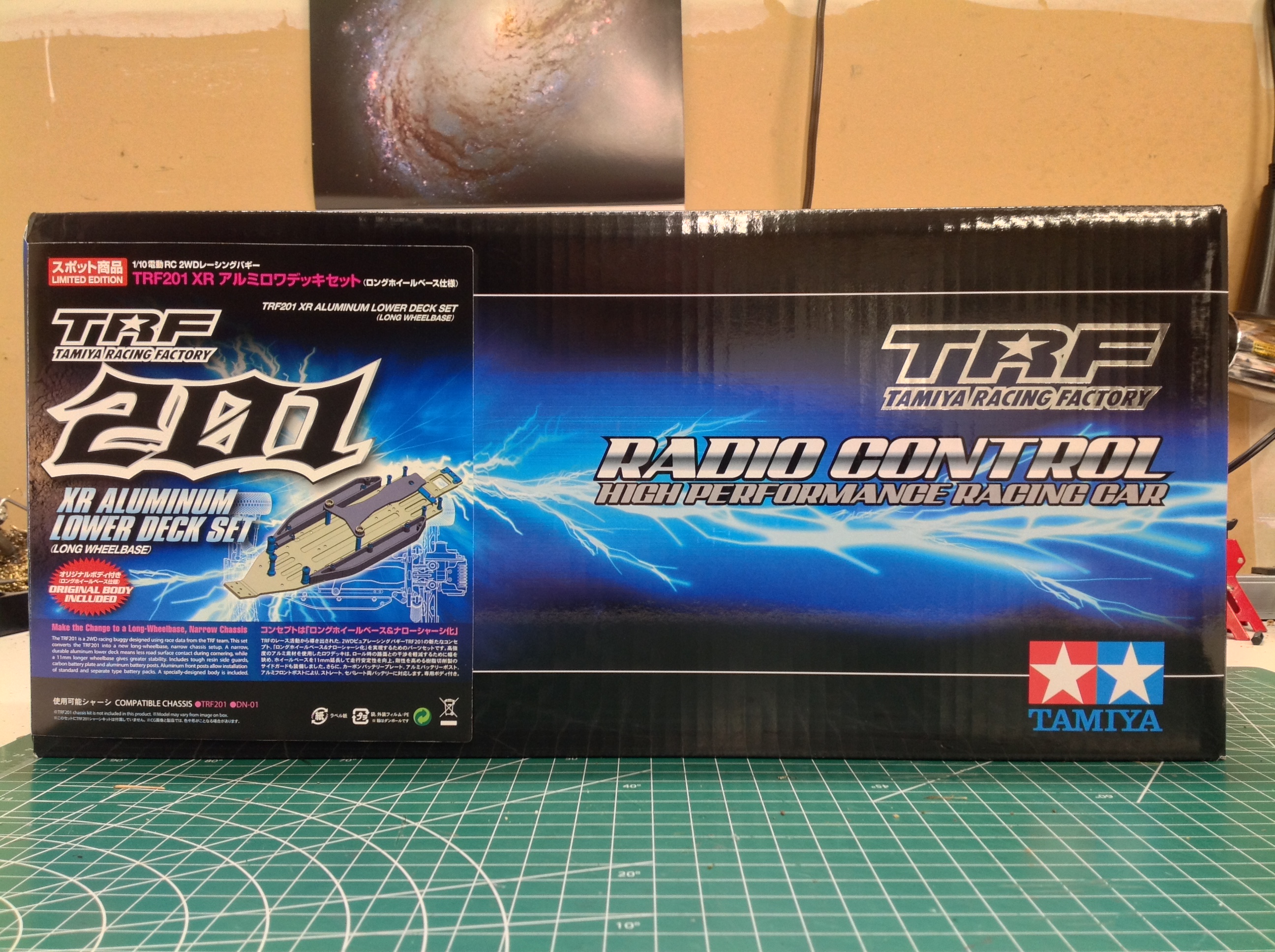
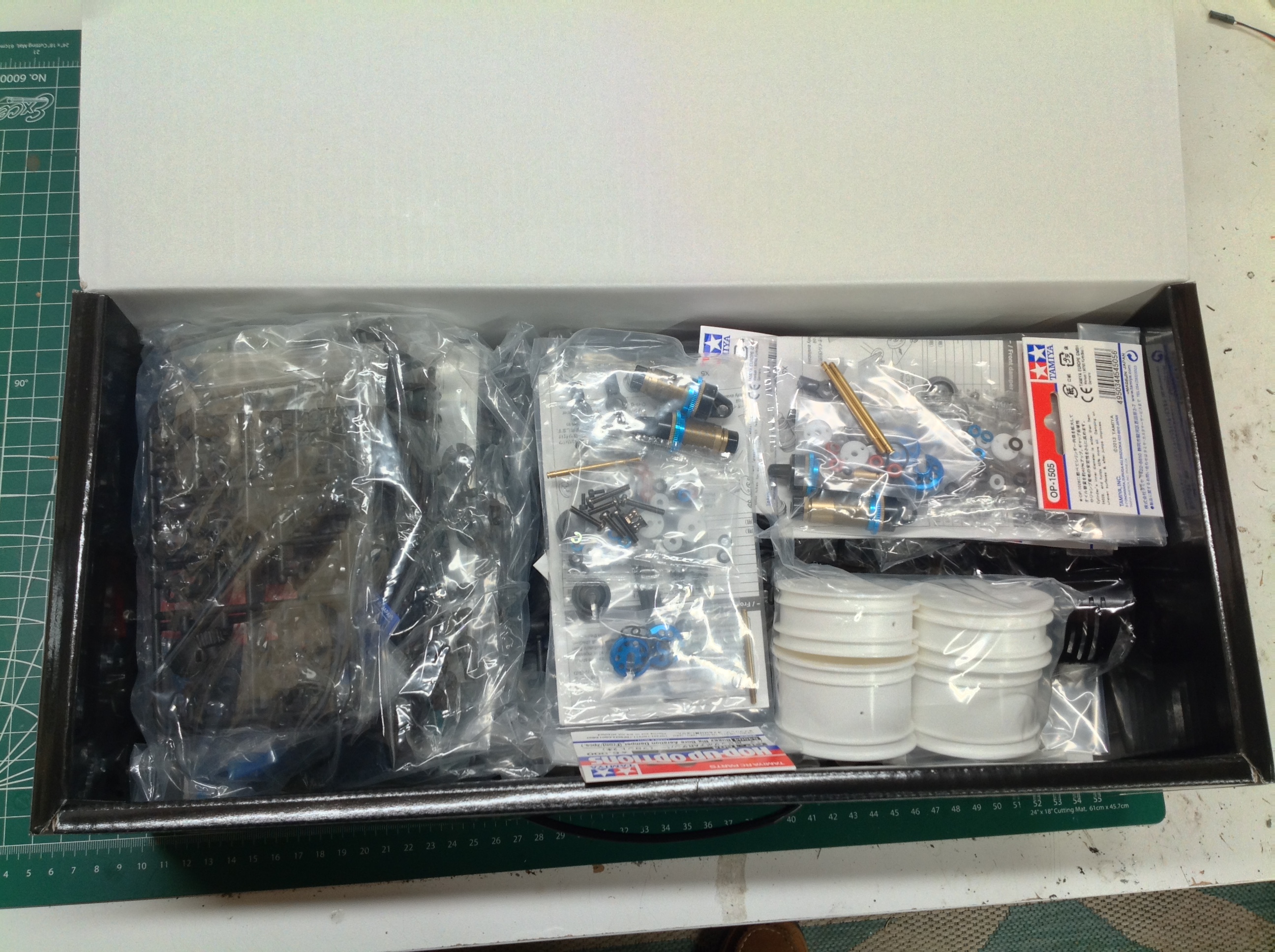
Considering the content of this box, it is really small. If you
look closely, you'll see that it is only labeled as an XR Aluminum Upper
Deck Set, not the 42167XR number under which it was sold. In the
picture on the right you see the contents after the body and wing were
already removed, and it still pretty much full. The parts you see
in individual packaging are the big bore shock upgrades. If I'd
had to pay full MSRP, this box would have cost ~$1100.
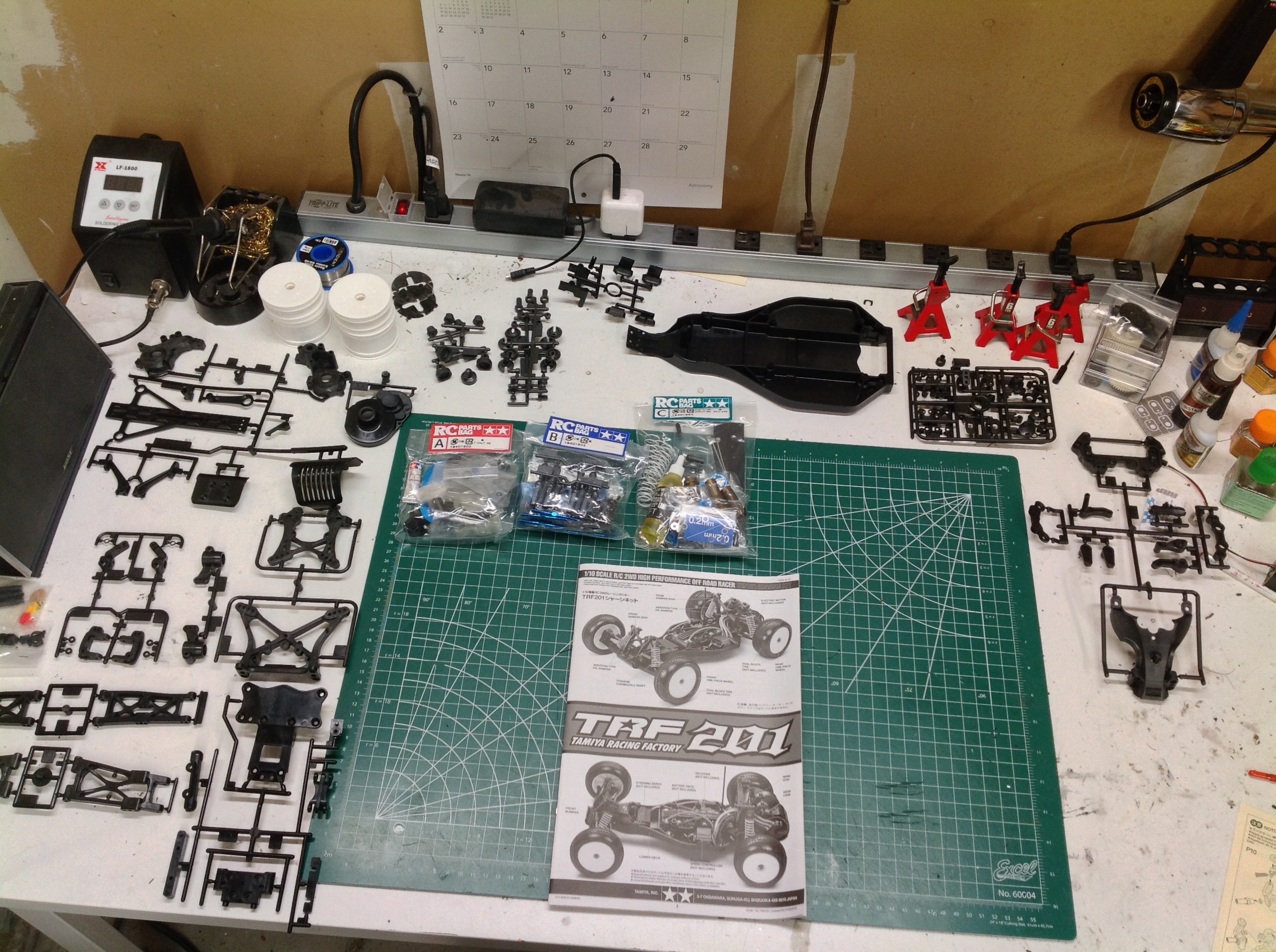
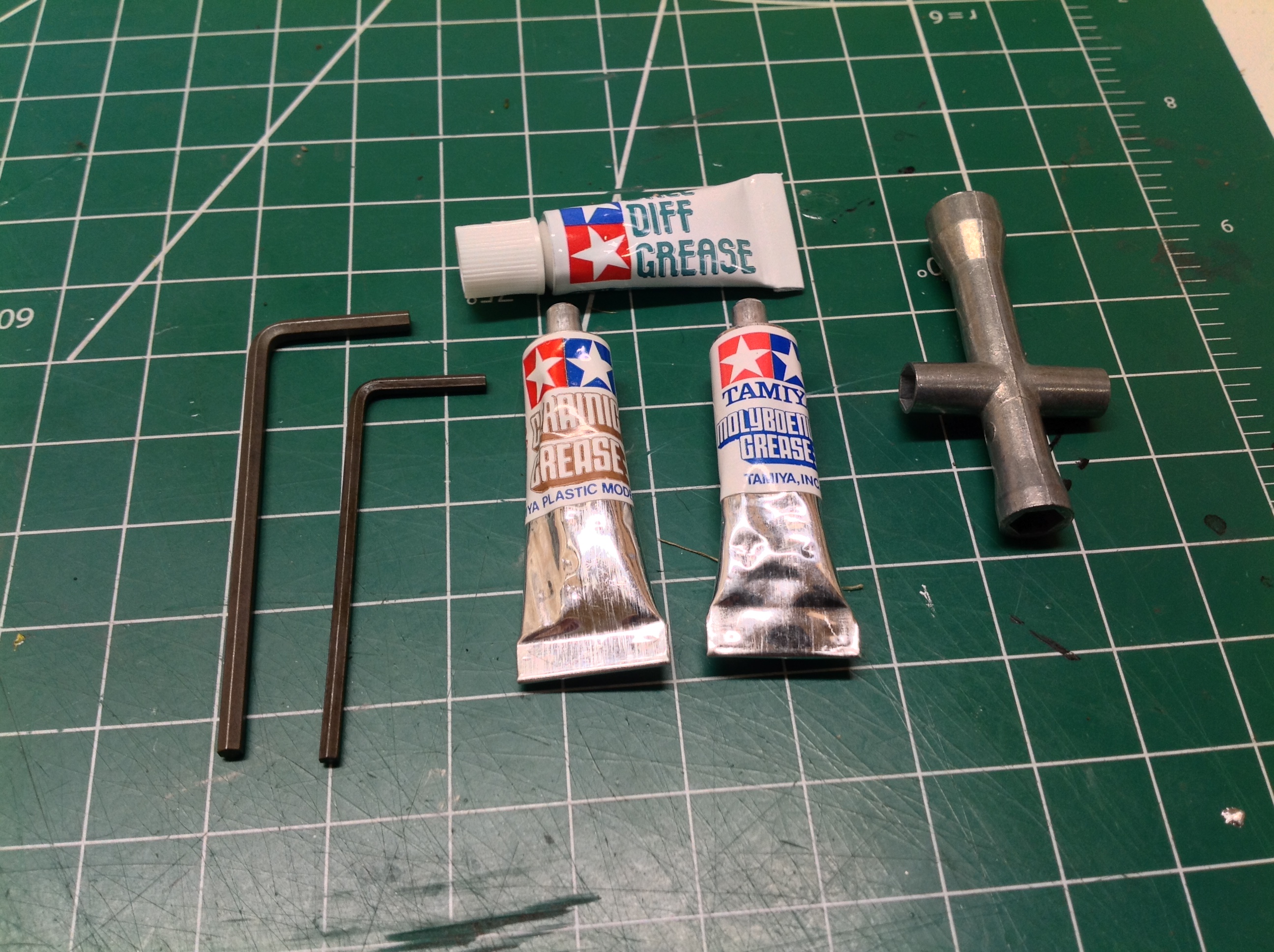
This is quite a complex set so it comes with a lot of parts. It
even comes with 3 different kinds of grease as shown on the right.
Beyond the large number of parts trees, the hardware bags are stuffed
full with aluminum parts and high quality hex hardware. There are
no tapping screws, only machine screws.
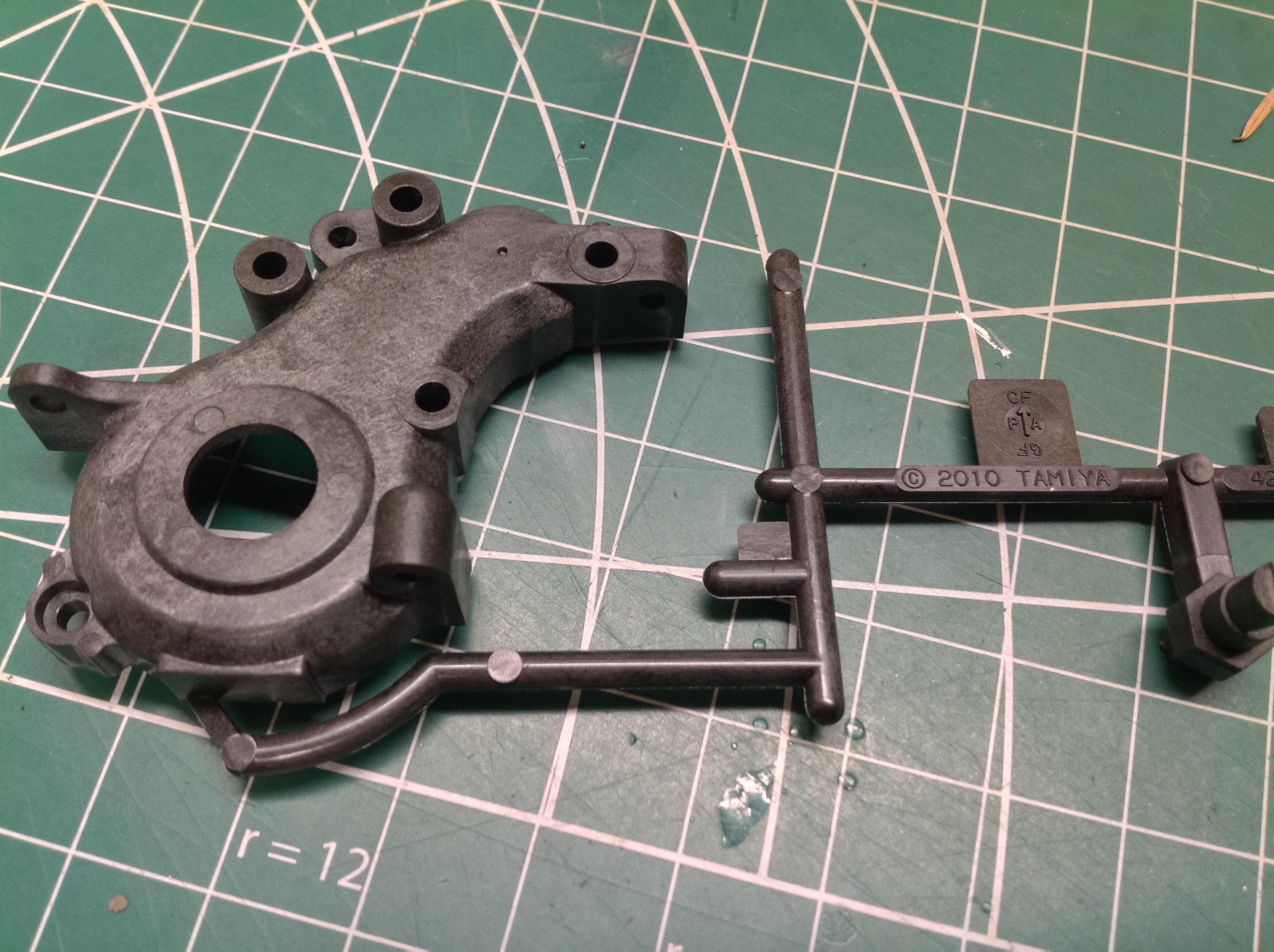
It is interesting to note the quality of the plastics in this kit.
Pretty much everything is reinforced in some way or another. If
you can read the molding codes you can see how. The gearbox
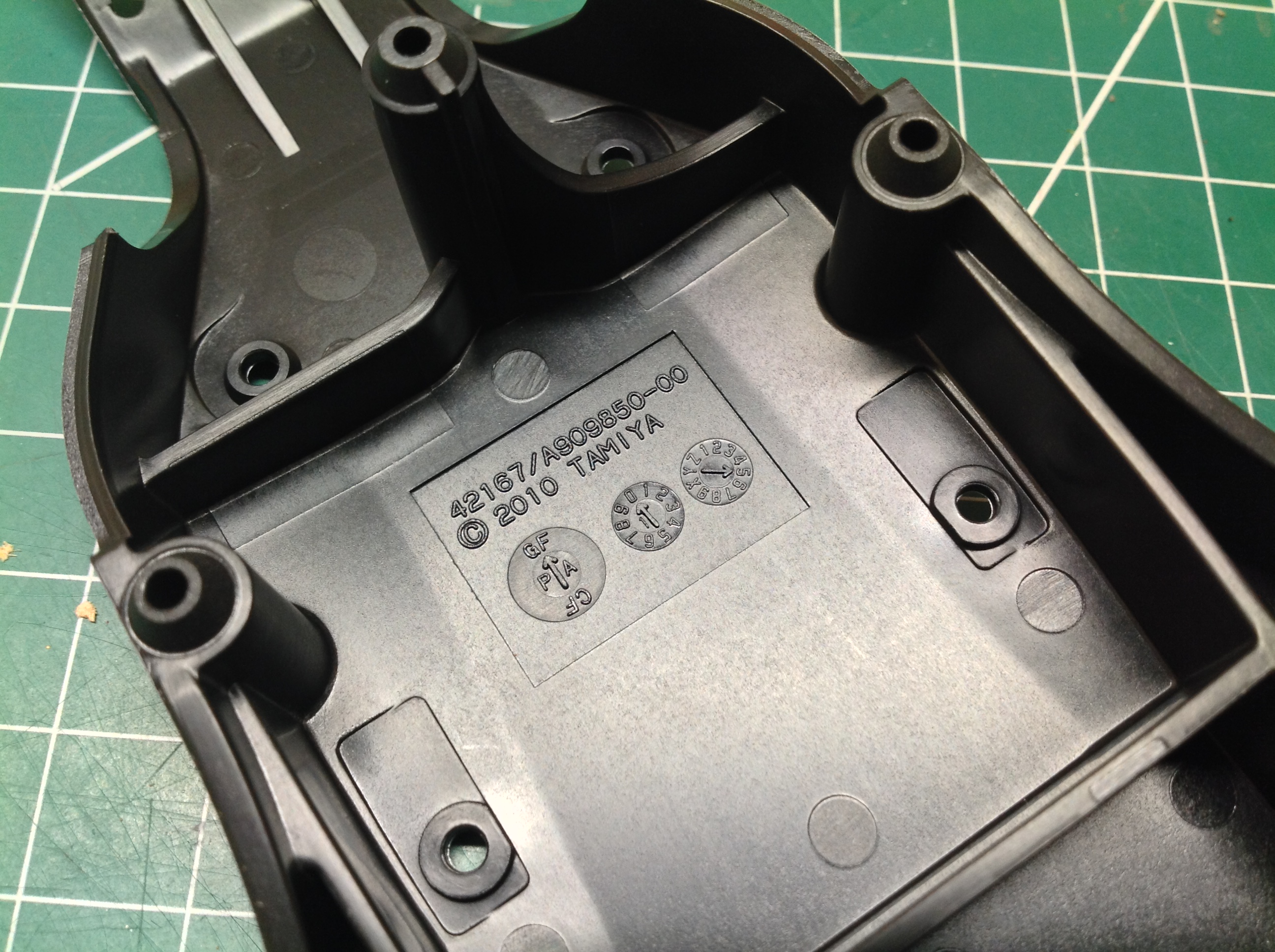
housing on the left is a carbon filled polyamide, probably Nylon.
The body tub on the right is a glass fiber filled polyamide manufactured
in May of 2010. All other things being equal, the carbon filled
will be stronger and stiffer and the glass filled will be more
resilient. The carbon fiber parts are so hard that the manual
recommends tapping the threads into the holes before installing any
screws.
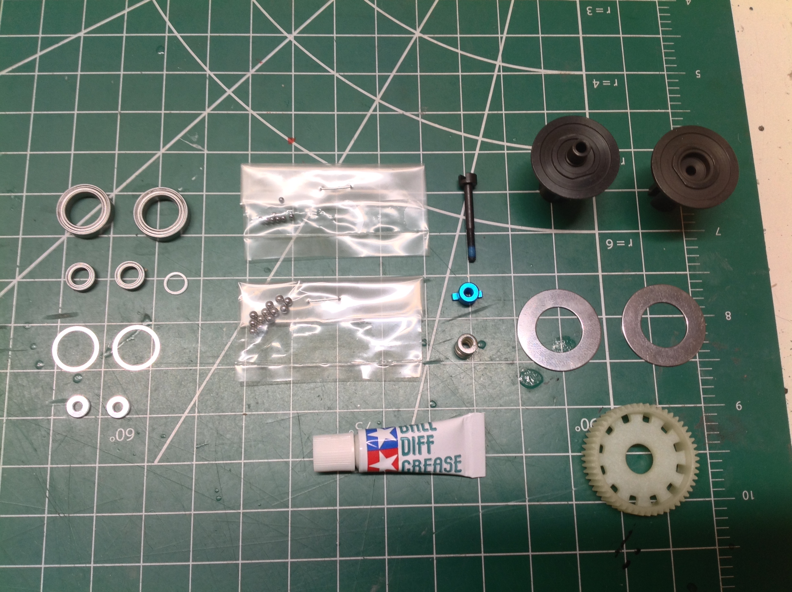
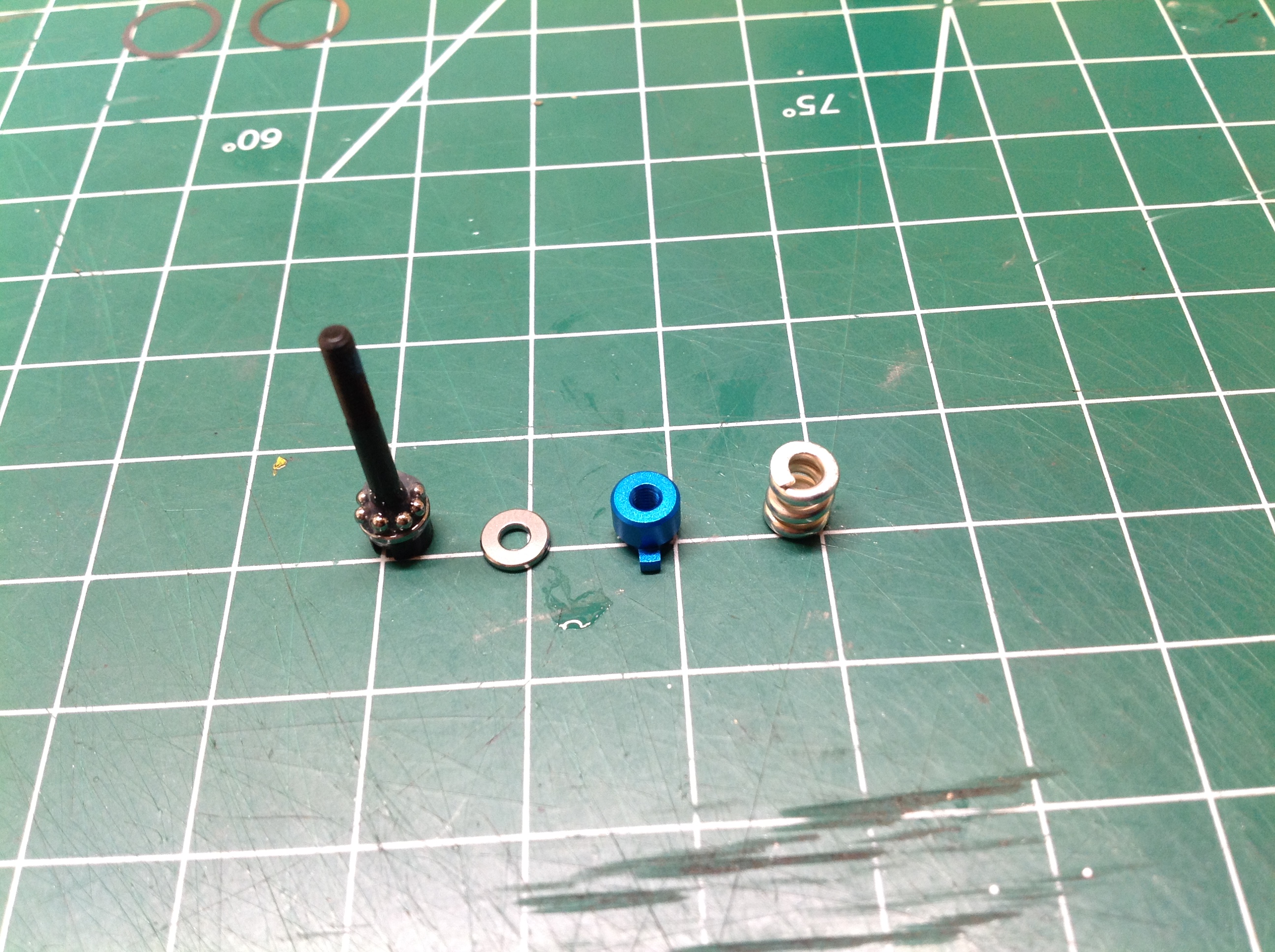
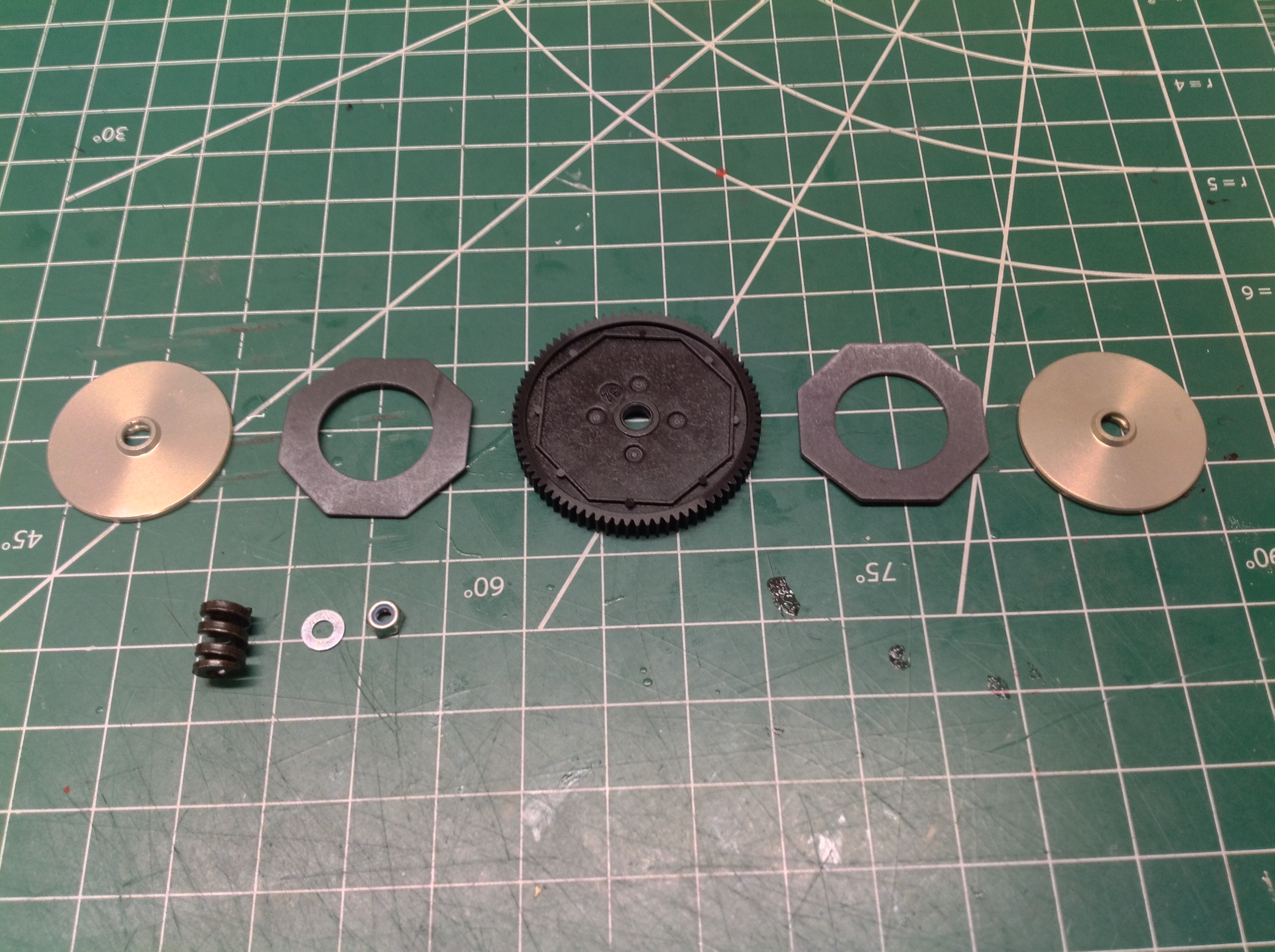
Step 1 is assembly of the ball differential. The picture on the
left shows the parts for this step. One unusual feature of this
kit is that it uses Imperial sized balls (like its builder). The
diff balls are 3/32" in diameter and the thrust bearing balls are
1/16". Presumably this is to make them compatible with American
racing buggies, though I'm not sure why it matters whether or not the
balls match. Perhaps racers are crazy enough to rebuild their
diffs between races and need to stock a consistent size of balls.
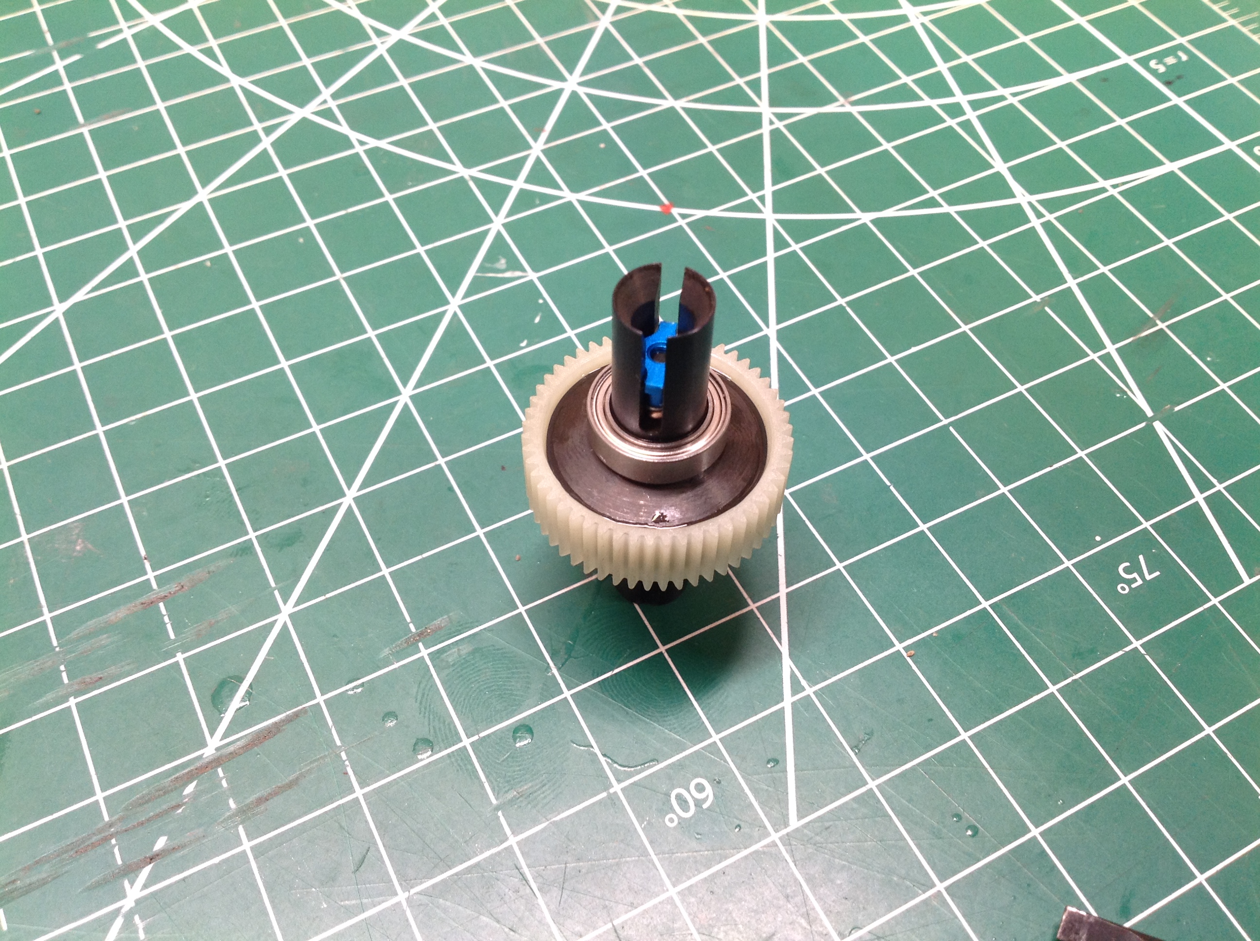
The diff uses nice hard steel drive cups and a Nylon gear. There
are a number of spacers and shims used to make everything fit perfectly
with no slop. The diff uses 12 main balls.
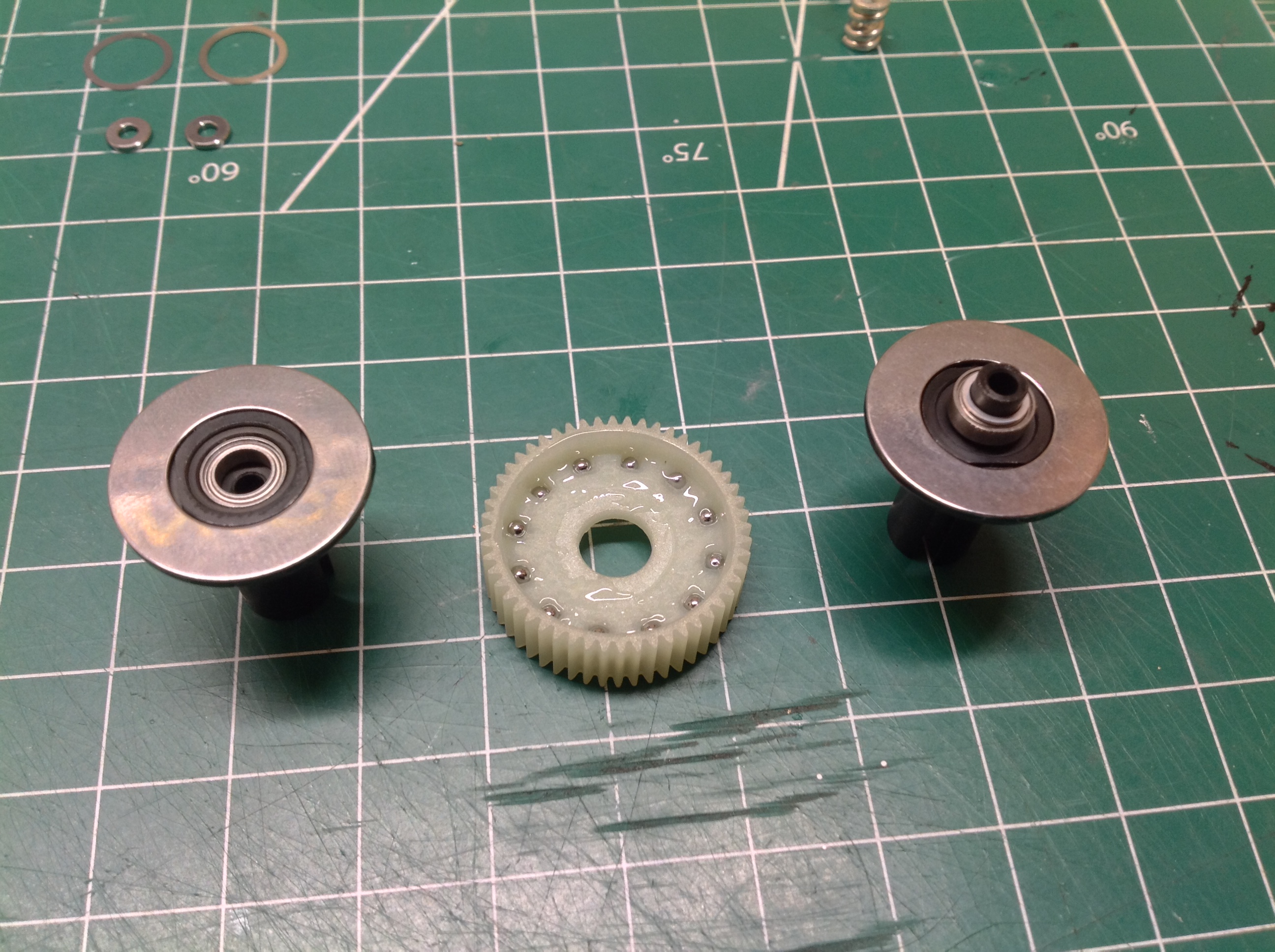
The thrust bearing needs to be carefully assembled from 8 balls and a
pair of thrust washers. The clamping nut is blue anodized
aluminum. The completed ball differential is shown on the right
with the 15x10mm support bearings installed.
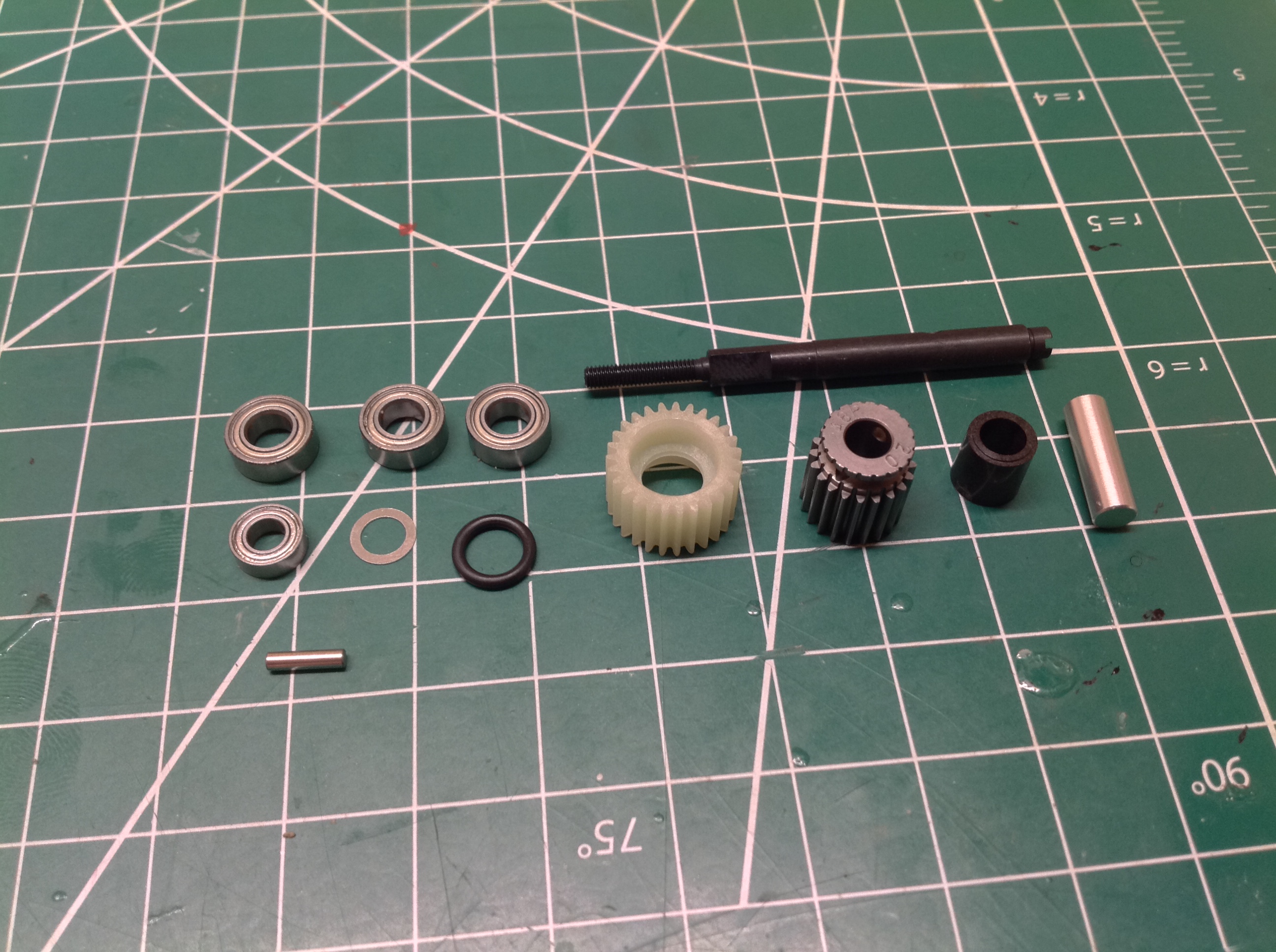
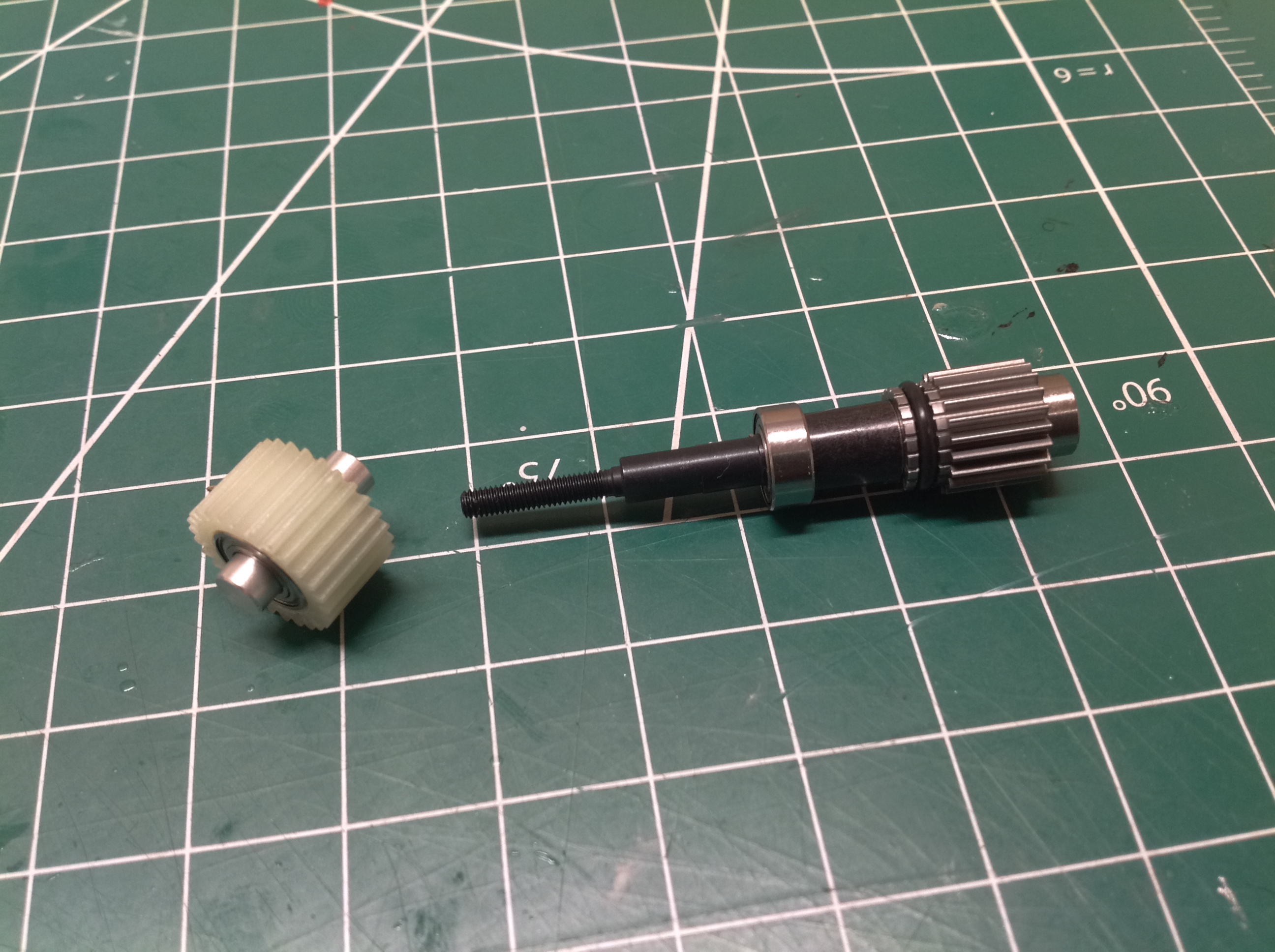
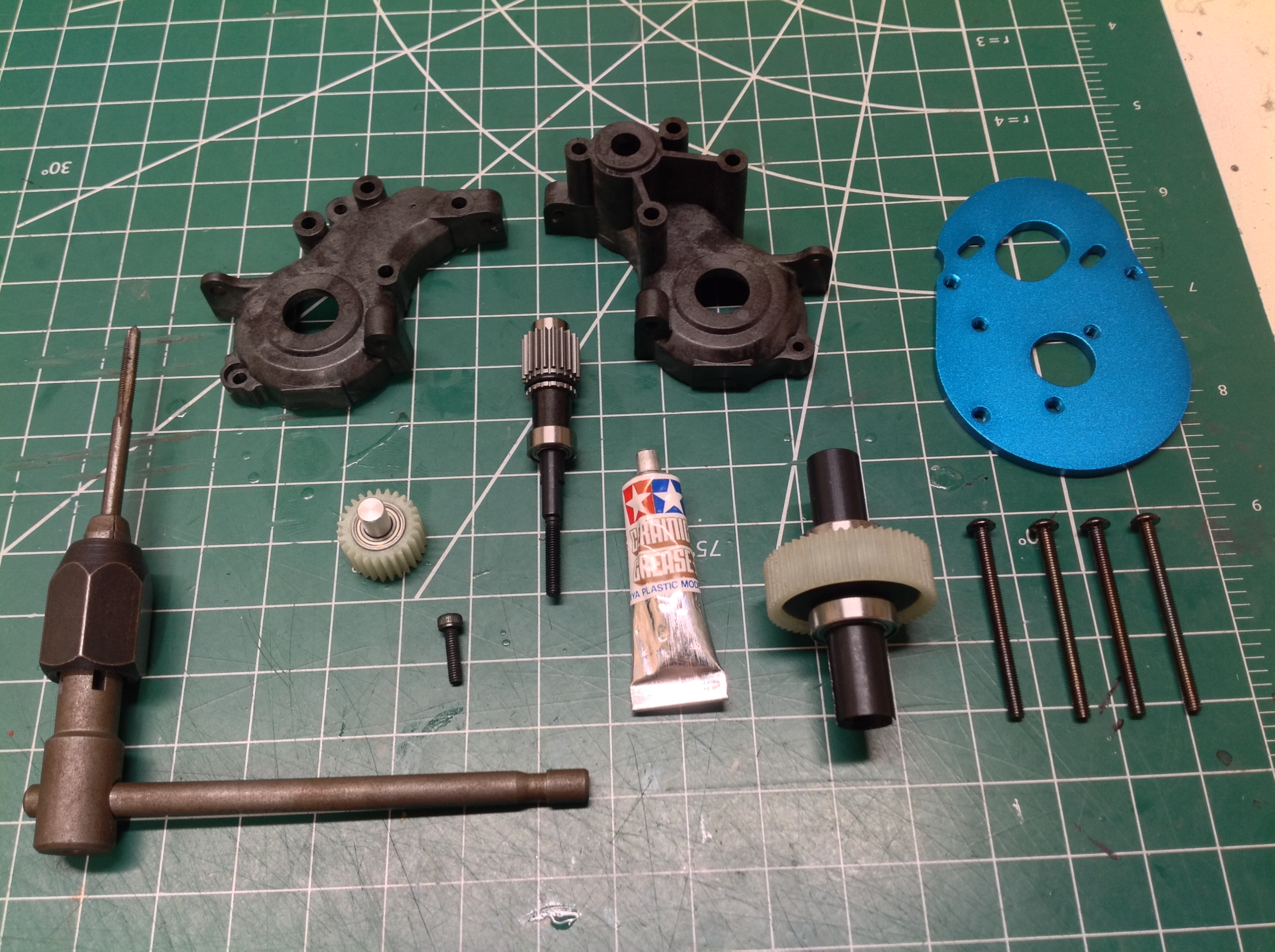
Step 2 builds the idler gear and counter gear. The idler gear
is Nylon and just sits on a pair of bearings and a solid shaft.
The counter gear assembly uses a steel shaft, a steel gear held with a
cross pin and retained with an o-ring, and some spacers and
bearings. I've always found the name "counter gear" odd, but I guess
it makes some sense. Because the spur gear will sit on the other
end of this shaft, it rotates in a direction counter to that of the
motor.
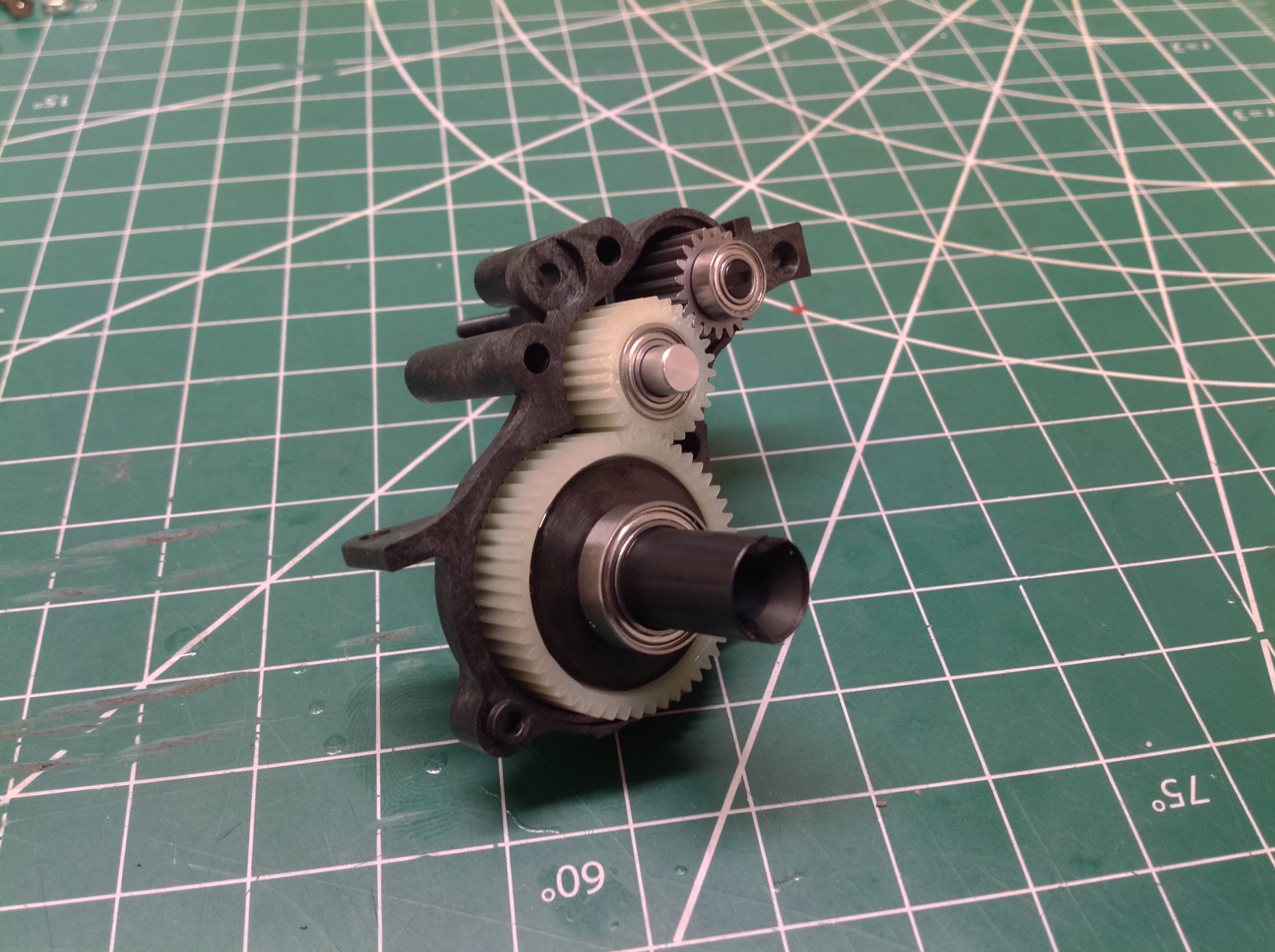
Step 3 assembles the gearbox. My 3mm tap was required to thread
some holes for this step. Some 36mm length 3mm screws were also
used to pass all the way through the gearbox to the motor mount.
These may be the longest Tamiya screws I've seen. The picture on
the right shows the differential, the idler gear, and the counter gear
installed in one half of the gearbox housing.
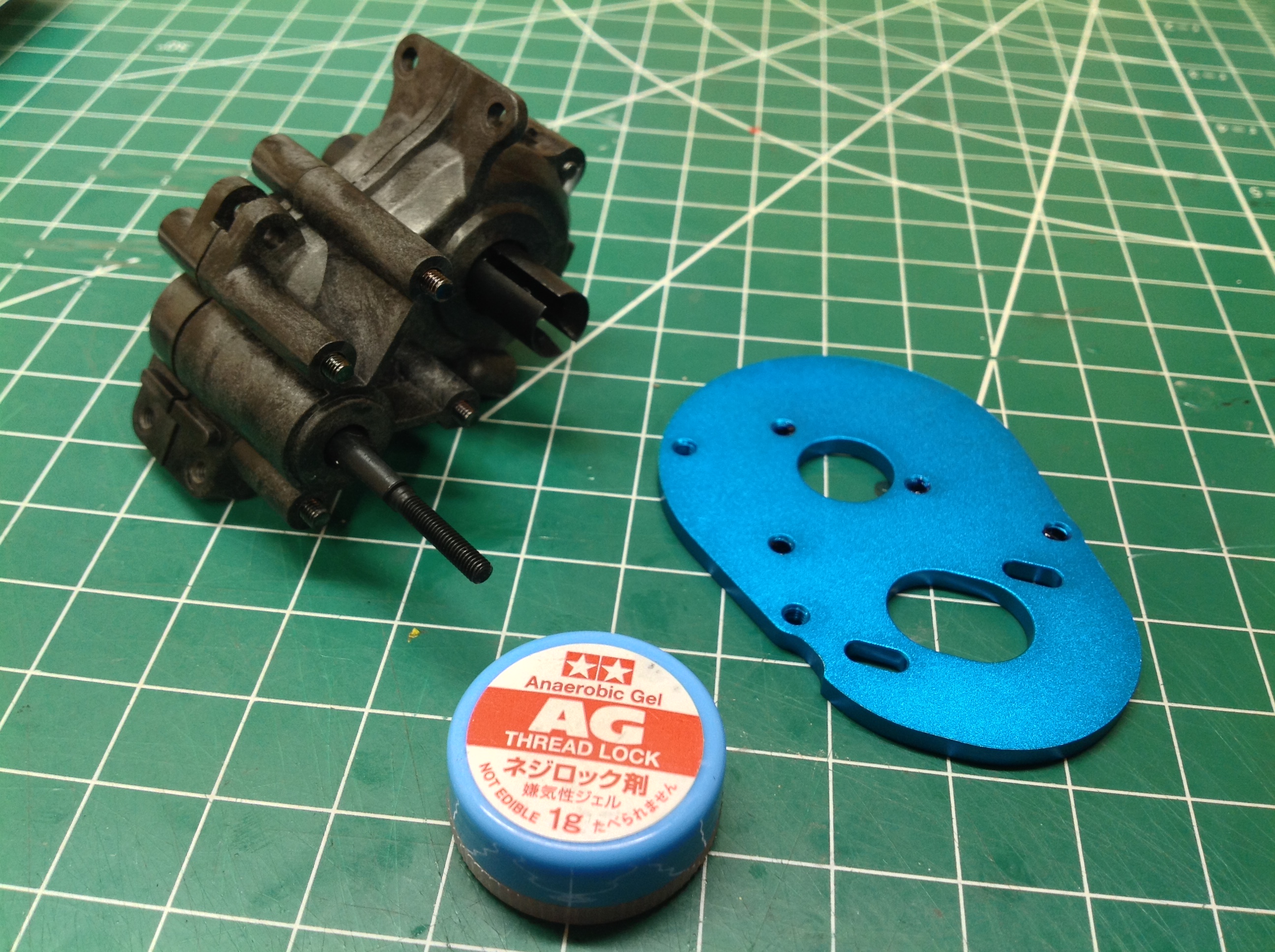
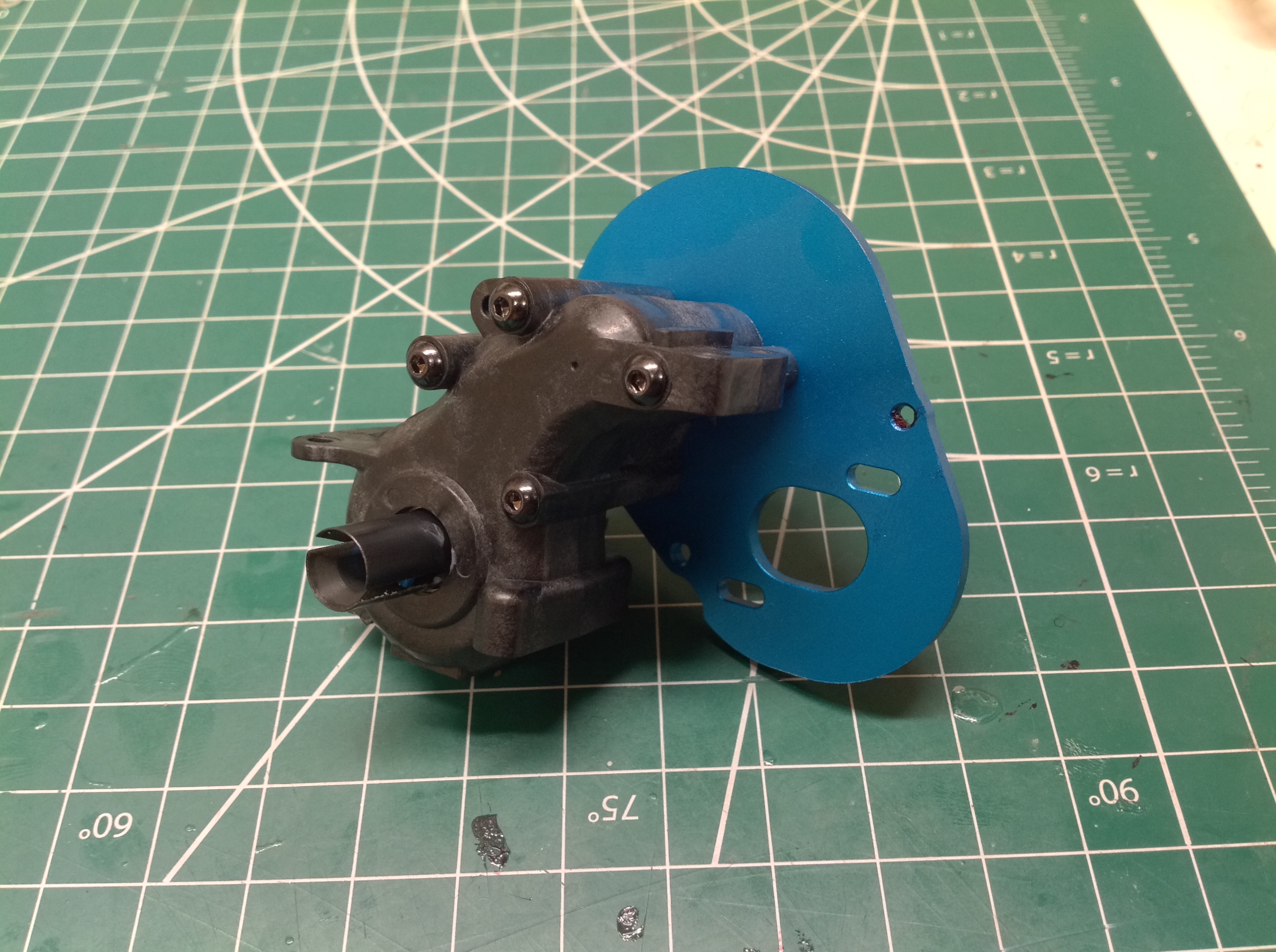
Once the gearbox is closed up the aluminum motor mount / heat sink can
be installed. Thread lock is required at this point but was oddly
not included in the kit. This is surprising given how otherwise
complete the kits seems to be.
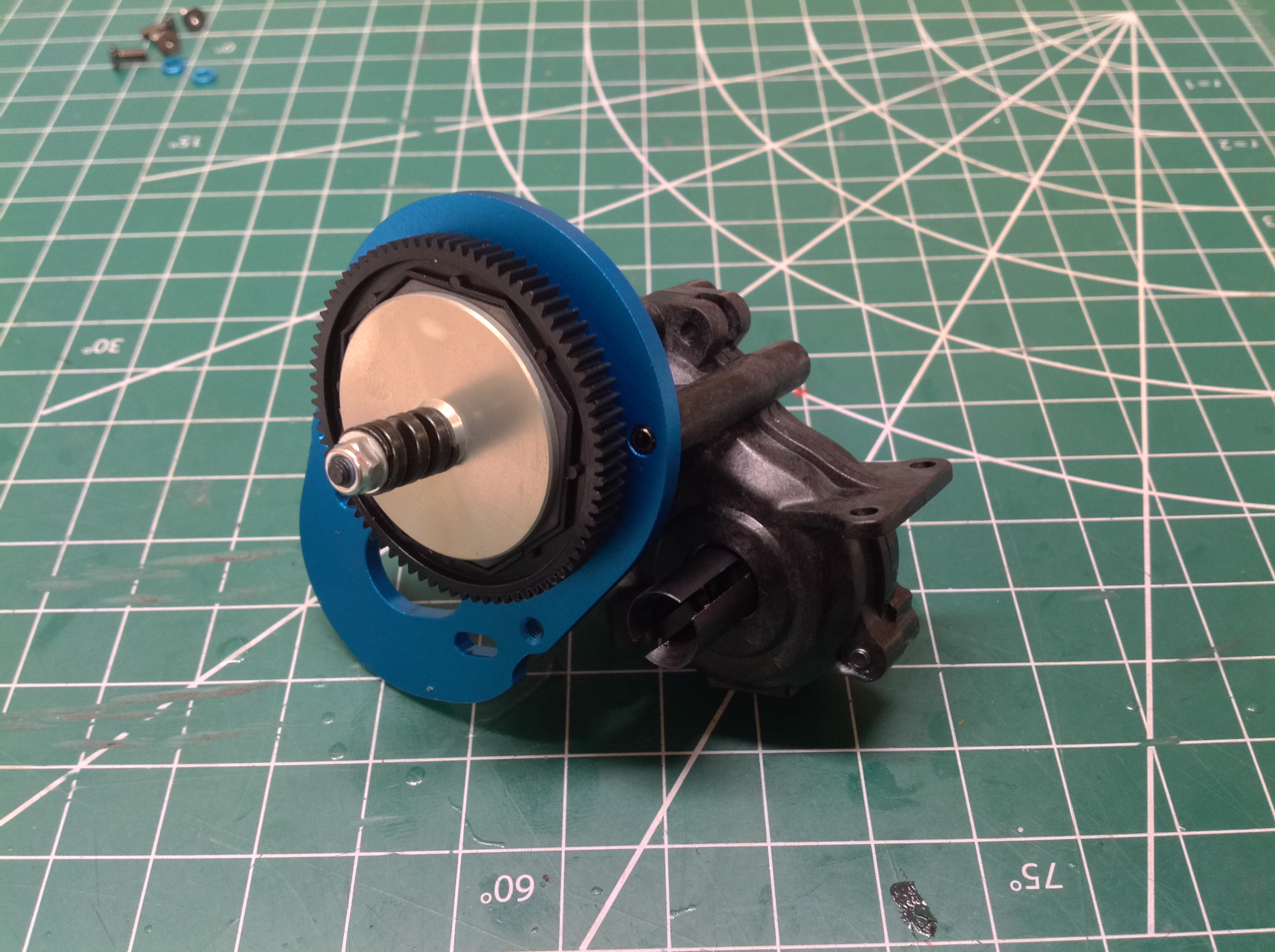
Step 4 builds and installs the slipper clutch. This kit uses a 48
pitch, 79 tooth spur gear to be compatible with American racers.
There are two slipper plates and two hexagonal pads. The spring
uses square wire, a type I've not seen in another Tamiya kit
before. The completed gearbox assembly is shown on the right.
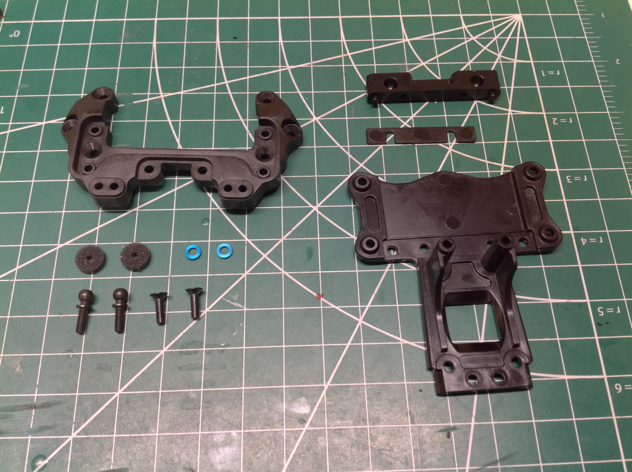
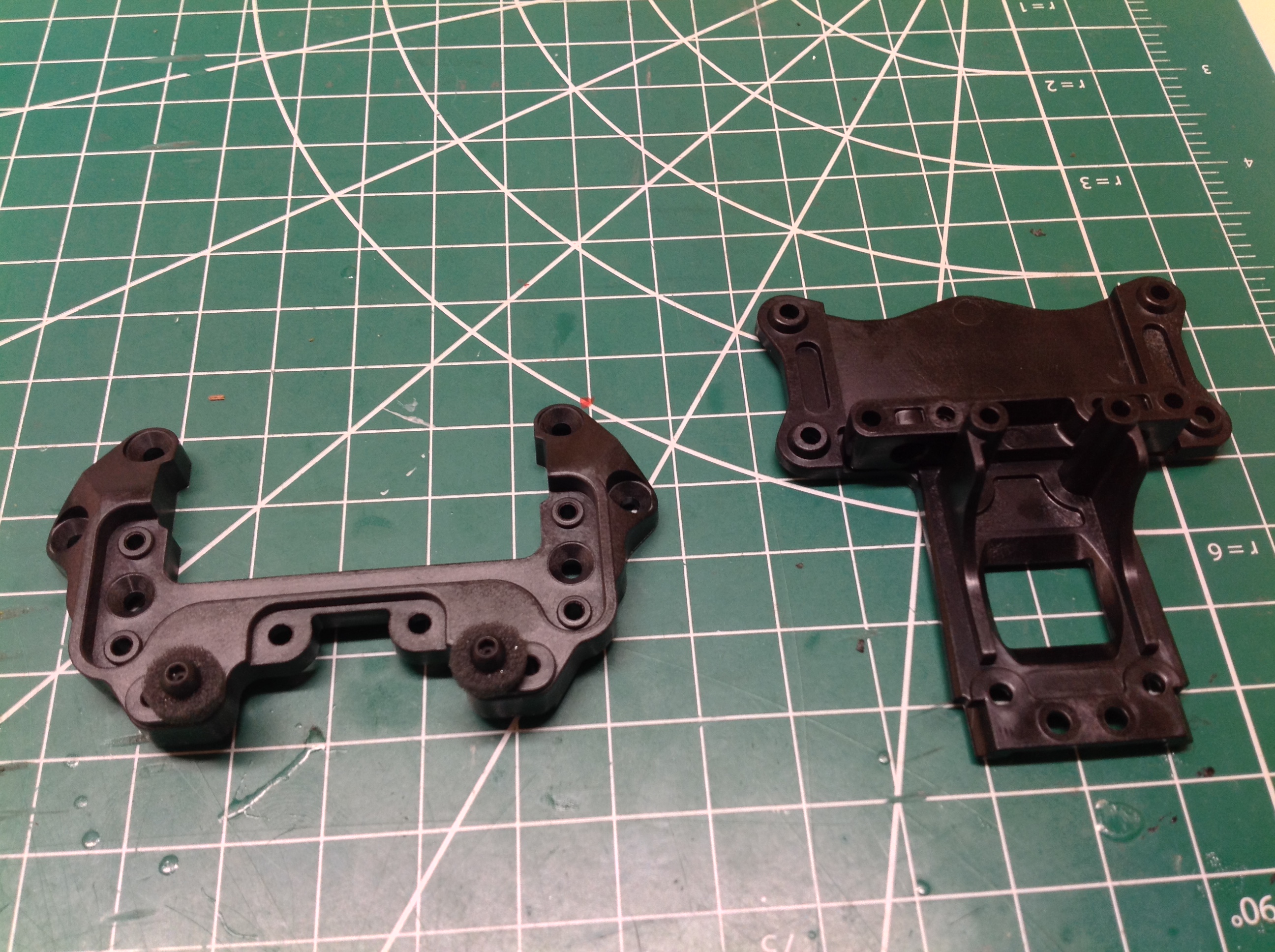
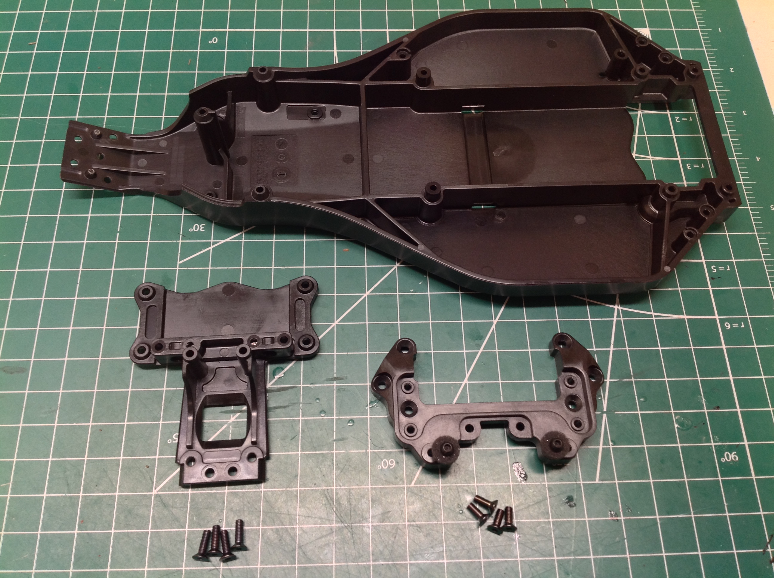
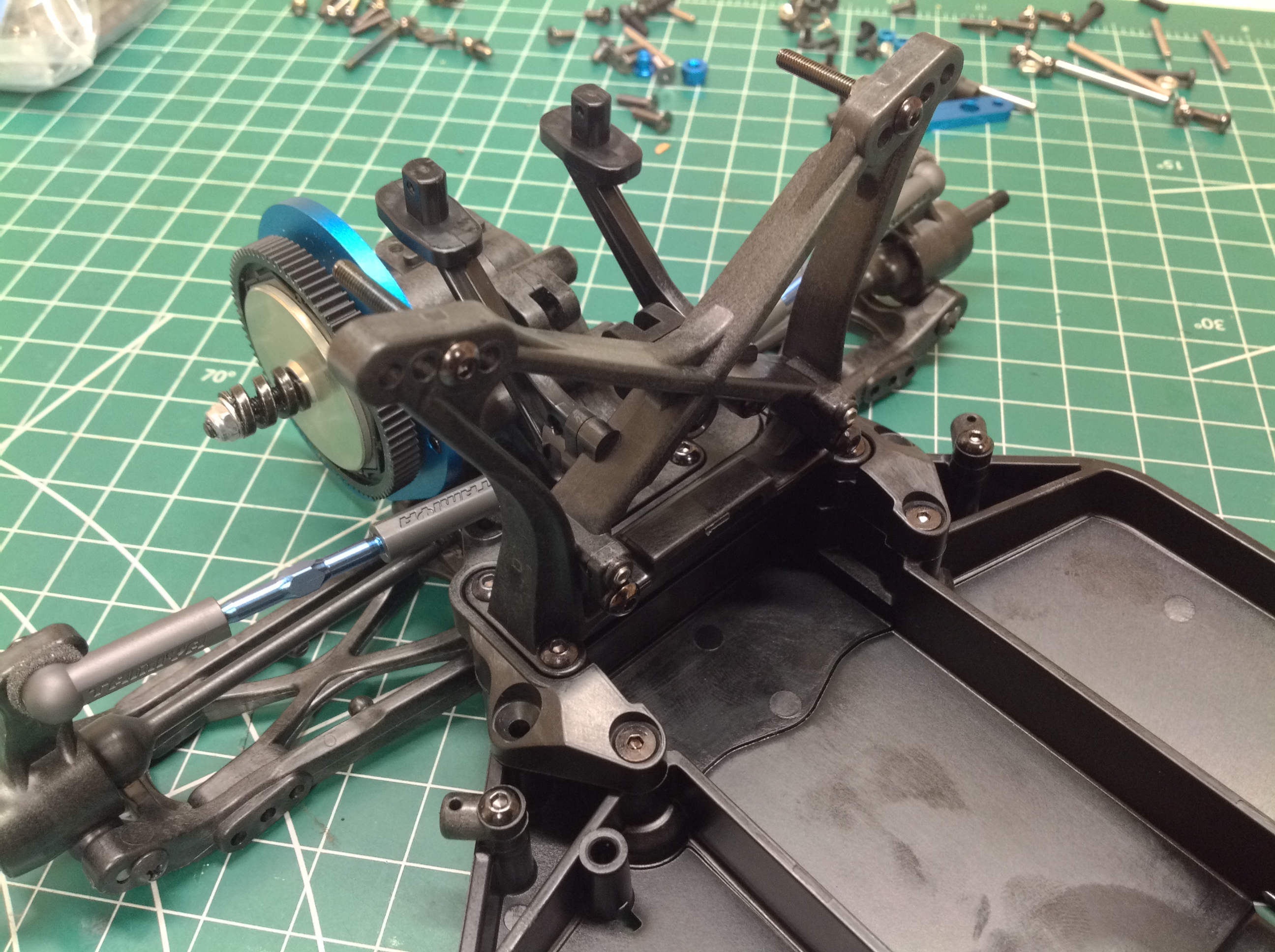
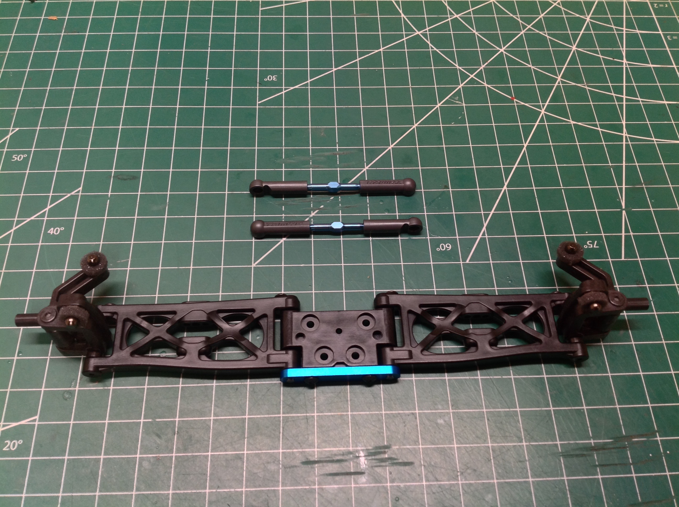
Step 5 builds the rear upper and lower decks. The upper deck will
support the shock tower and turnbuckles and the lower deck will support
the lower suspension arms and gearbox. On the right you can see
that some ball joints were added to the upper deck and protected from
contamination by foam rings. The lower deck has had the front
suspension mount installed. The spacing of the holes on this mount
along with the matching mount on the rear will determine the rear toe
angle.
Here in Step 6 the rear decks are attached to the chassis tub with a
pile of countersunk hex screws as shown. This is a very simple
step.
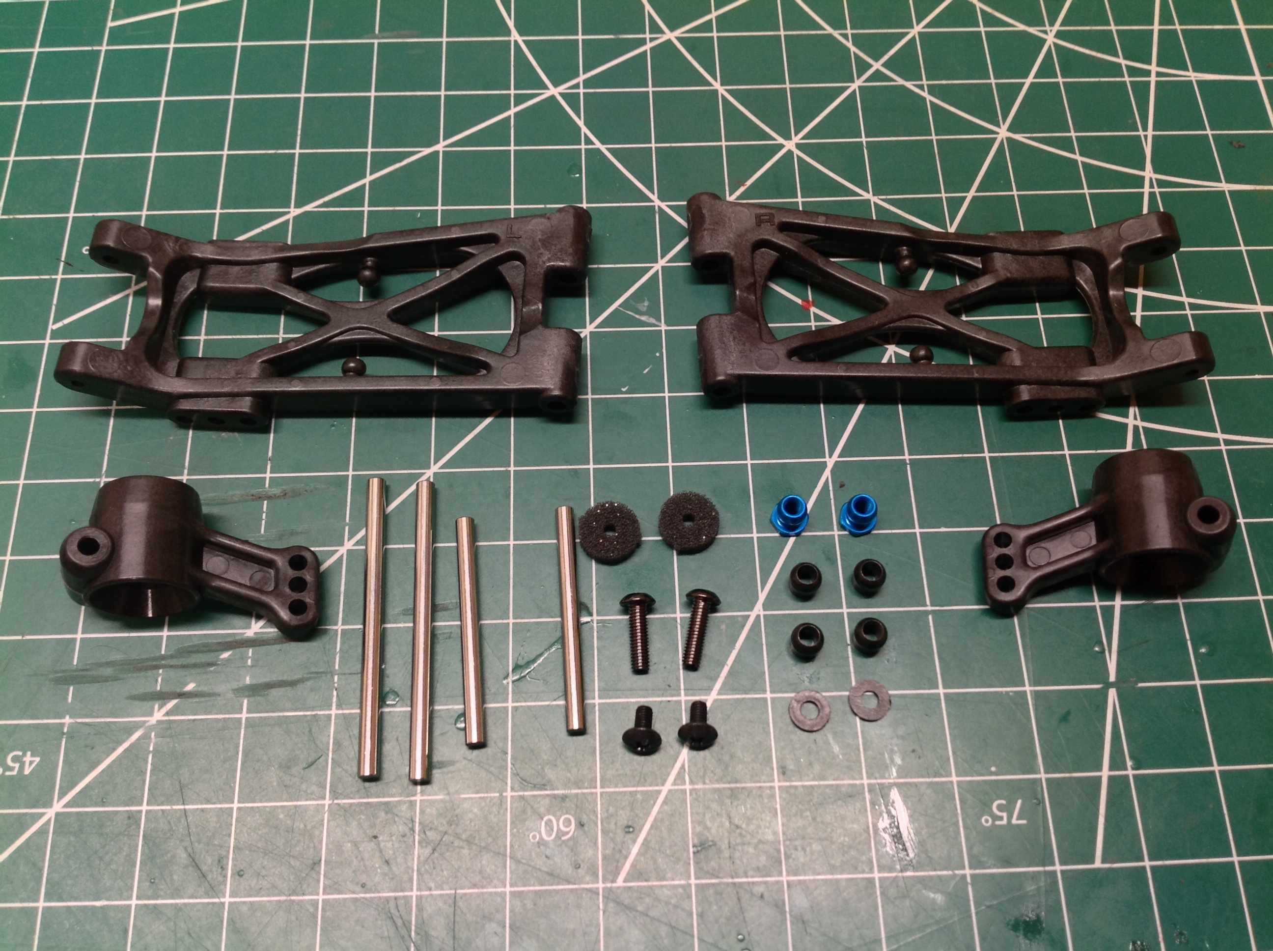
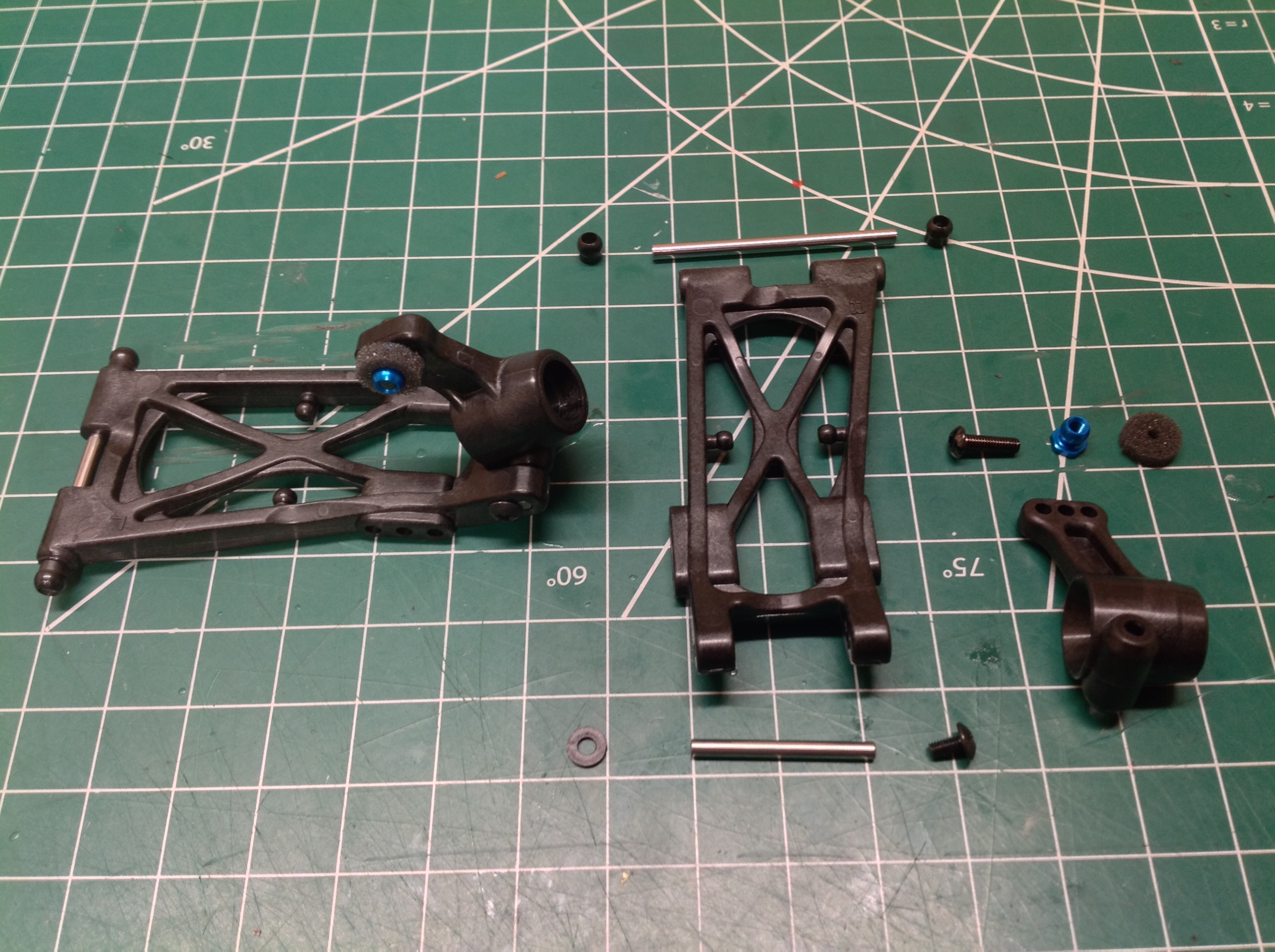
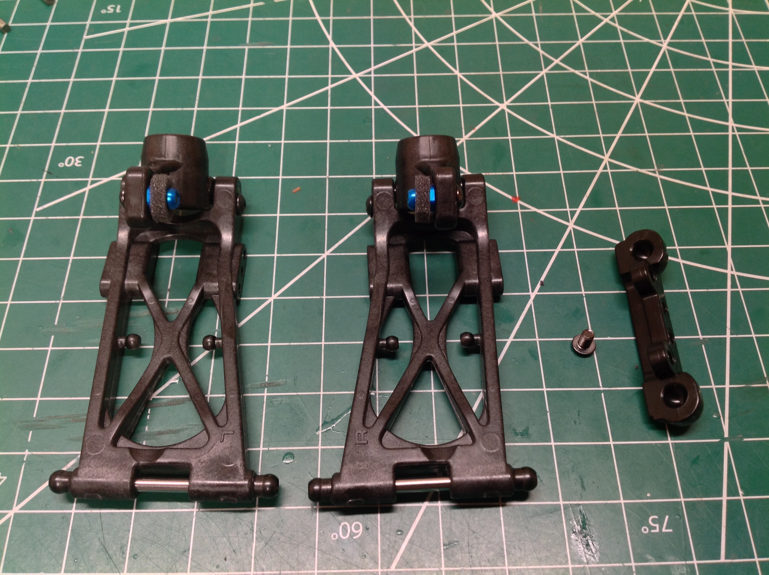
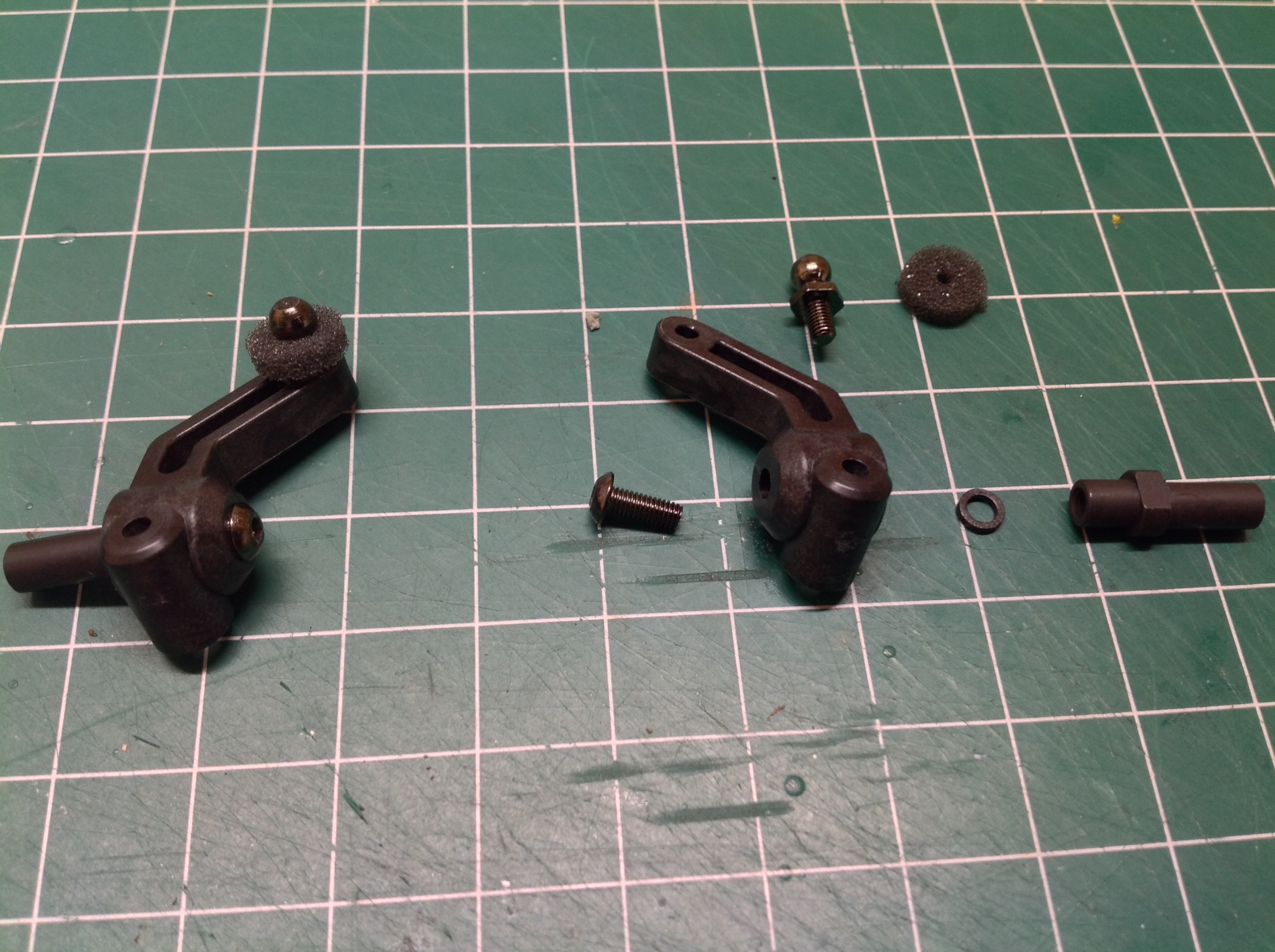
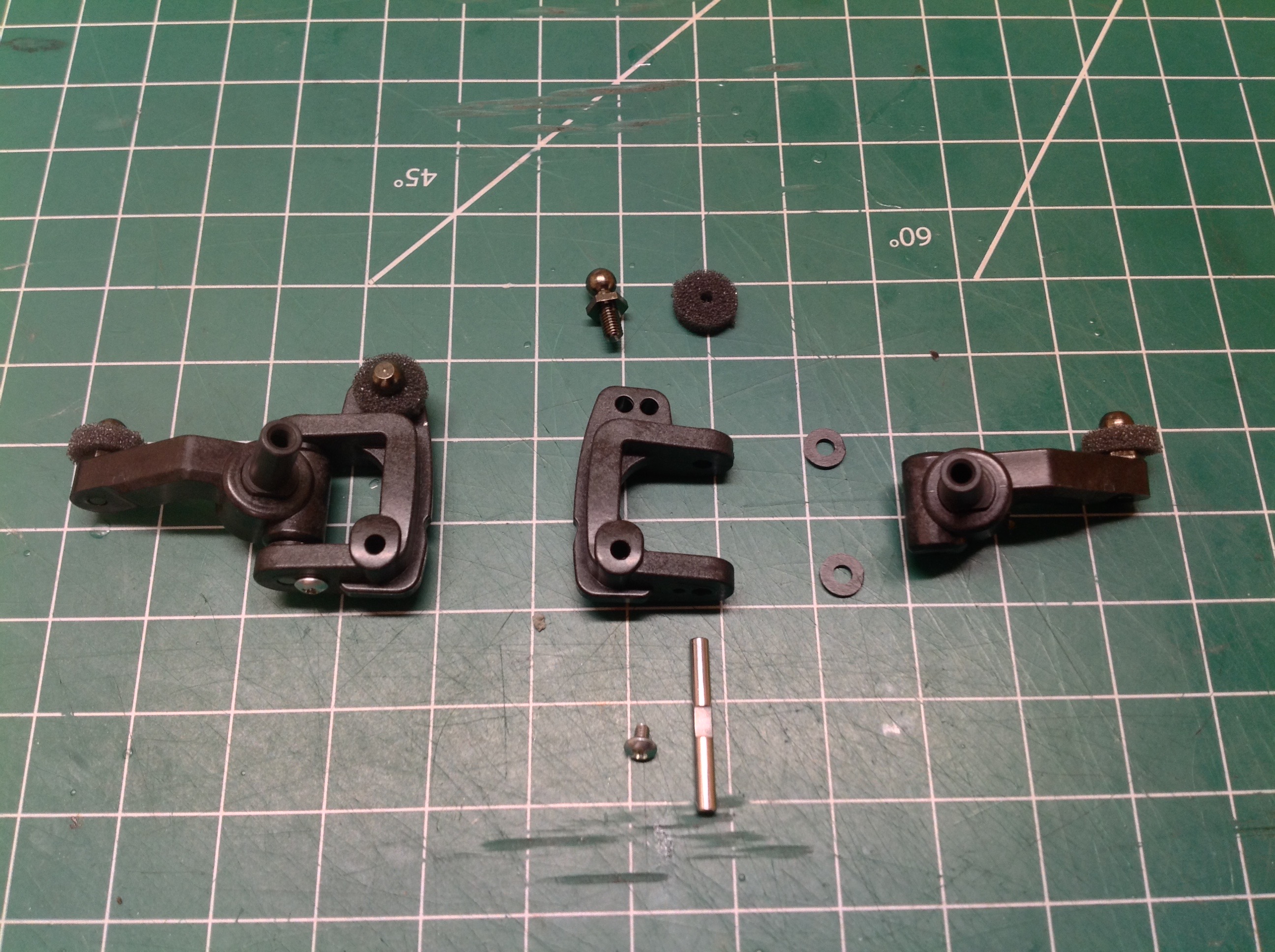
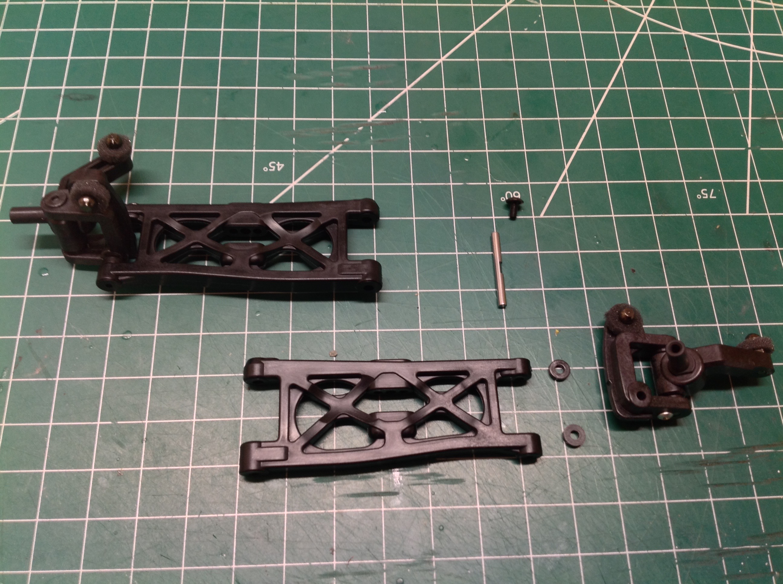
Step 7 builds much of the rear suspension. The lower arms are
angled slightly back. They can be switched left to right to alter
the wheelbase. The vertical hubs are installed backward. By
that I mean they are labeled with L for Left and R for Right but they
are installed opposite that. The hubs install to the arms with
2.6x27mm shafts with spacers on either side of the hub for a perfect
fit. There are no E-clips to install. Instead the shaft is
retained with a tiny screw whose head overlaps it. An exploded
view of the assembly is shown on the right.
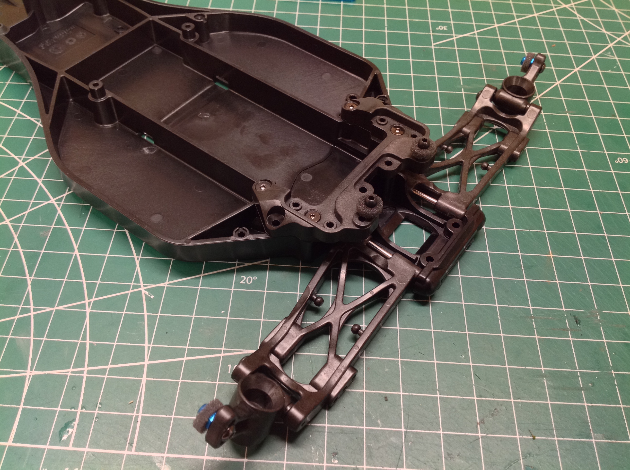
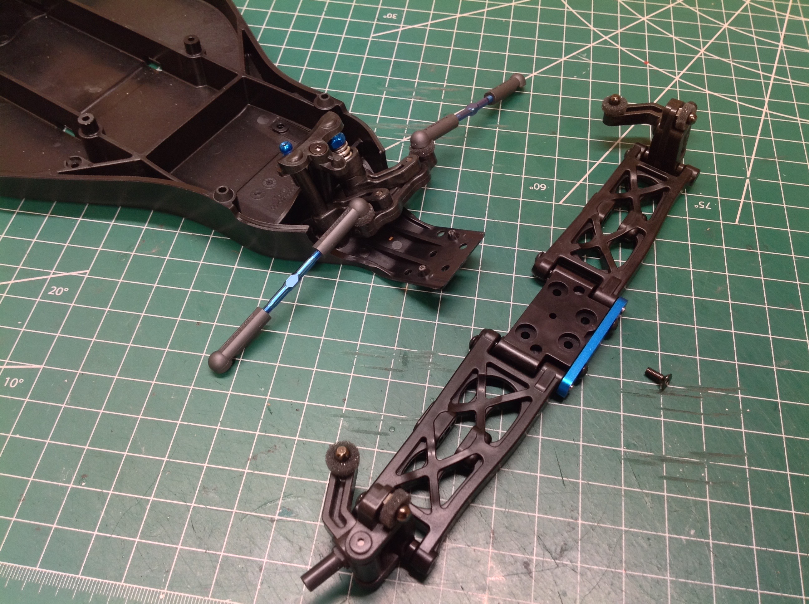
Step 8 installs the rear suspension to the chassis using only the rear
suspension mount and a temporary 3x5mm screw. When the bumper is
installed later this screw will be replaced with longer versions that go
through both parts.
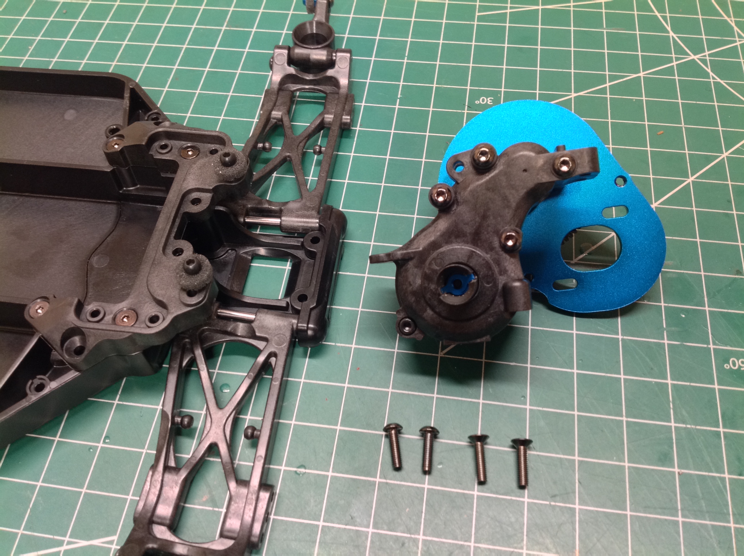
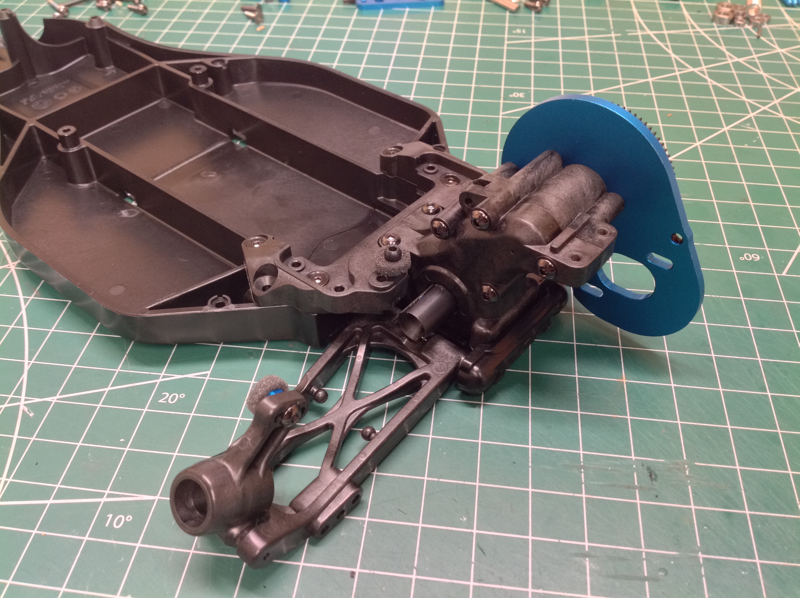
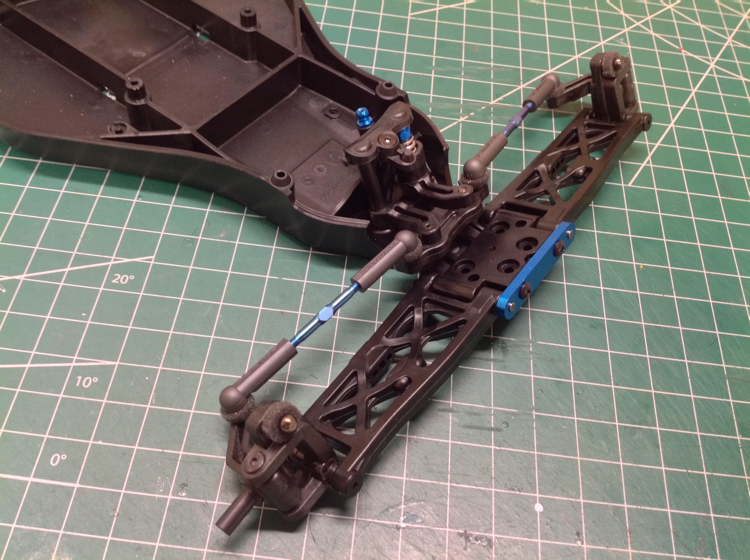
Step 9 mounts the gearbox to the chassis. Two screws are
installed from the bottom through the chassis plate and another 2 are
installed from the top into the rear upper deck. This split
support allows the whole gearbox to act as a stiffener for the rear
chassis.
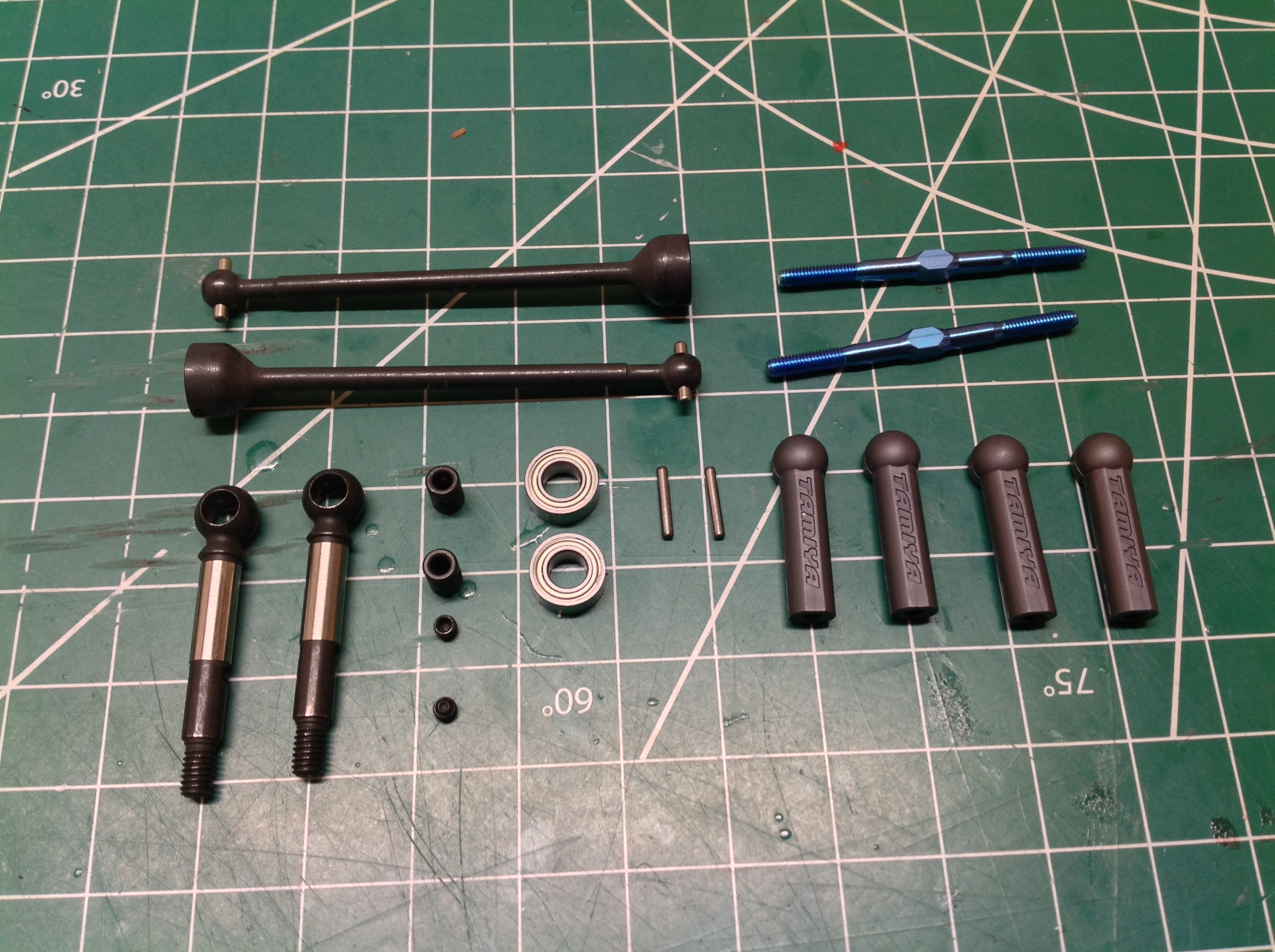
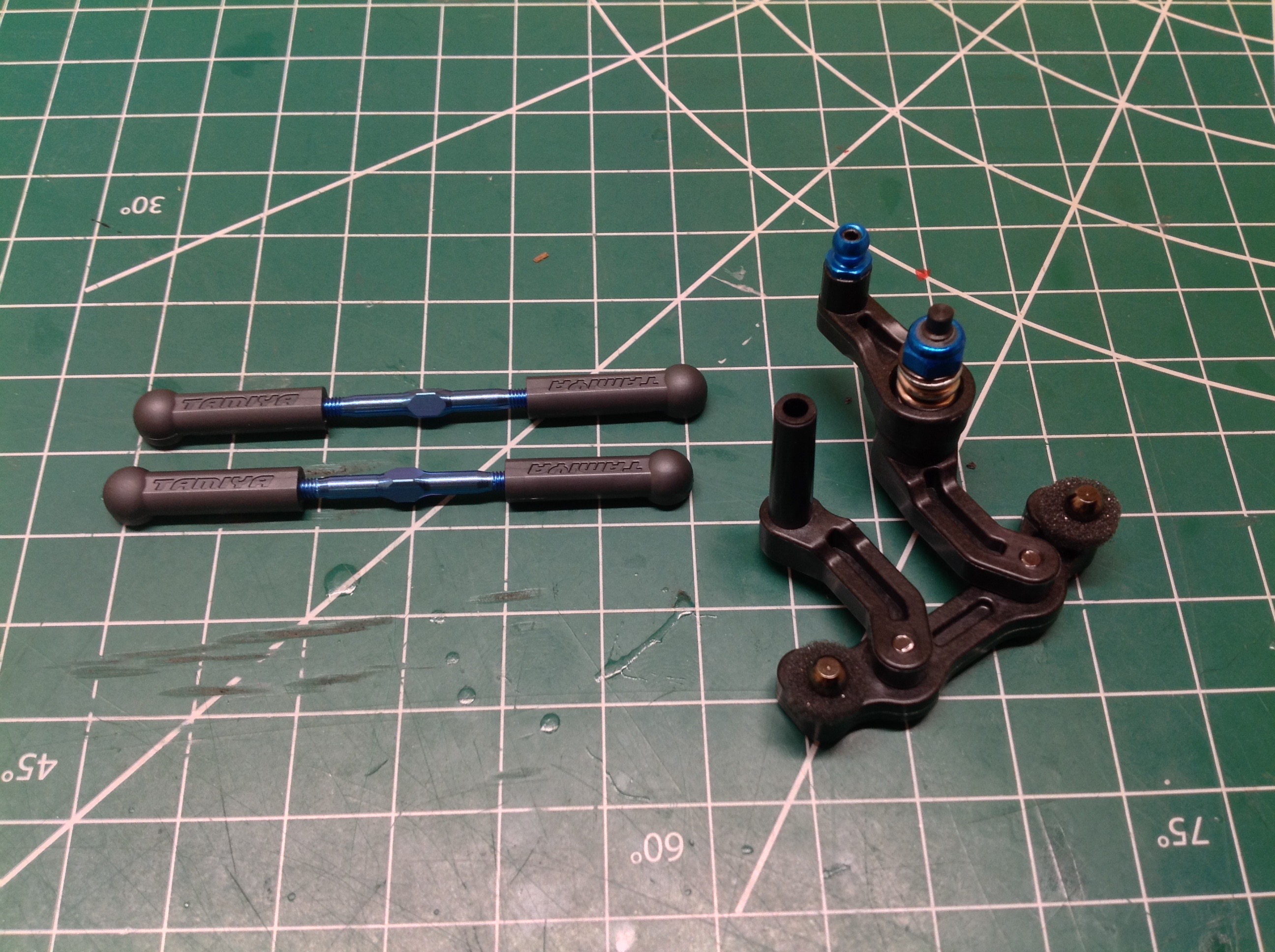
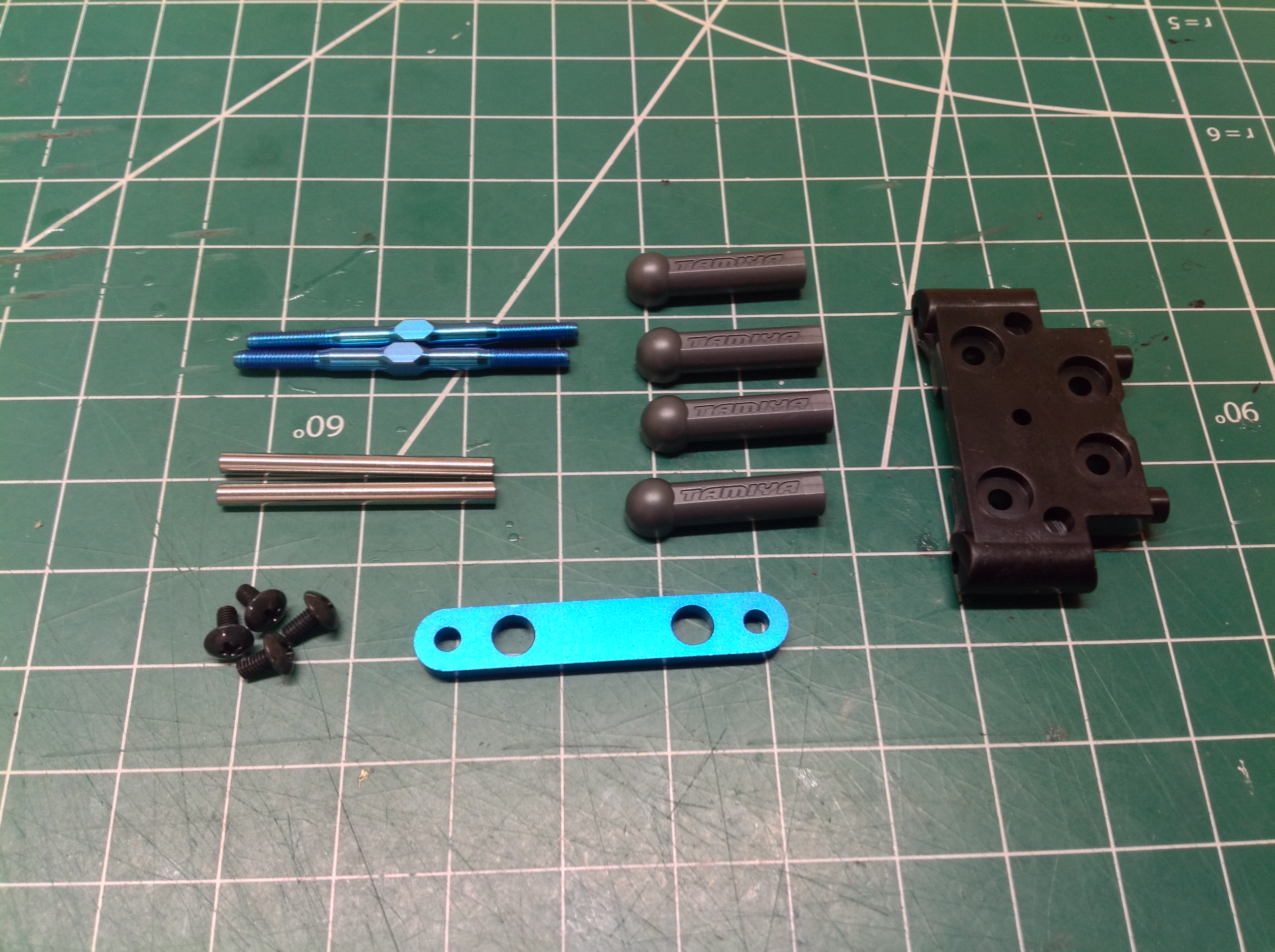
Step 10 builds the rear universal axles and upper links. The axles
consist of a swing shaft, a cross joint, an axle a pin, and a grub
screw. The links use blue anodized titanium and they look really
nice. The ball cups are a special type that fit very tightly.
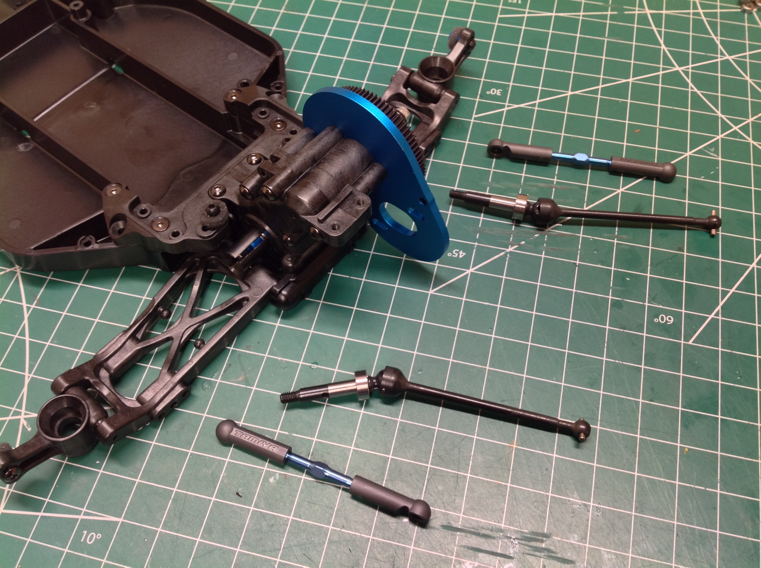
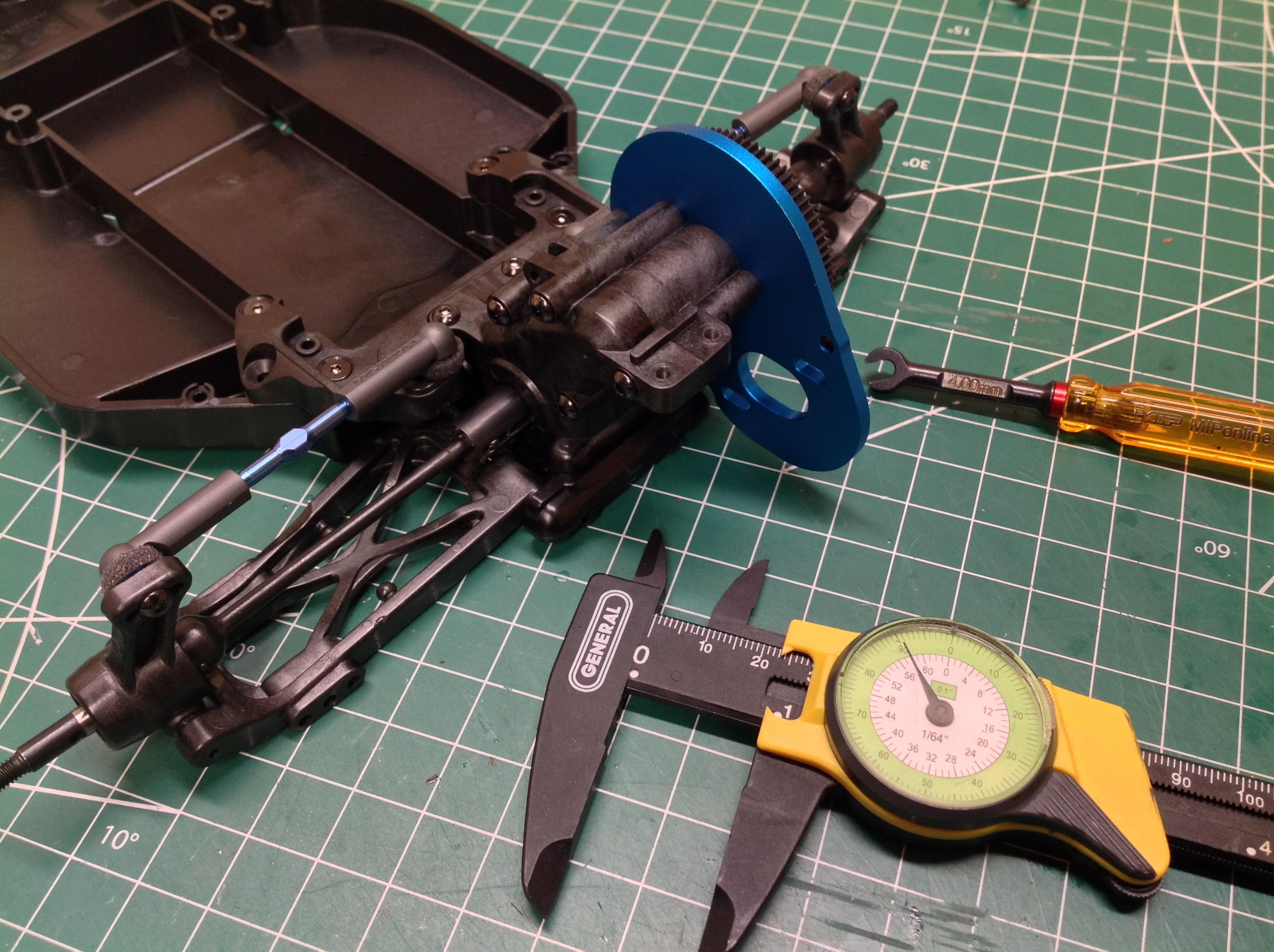
Step 11 installs the parts from Step 10 onto the chassis which completes
the rear suspension. It is a real pleasure to run this suspension
through its range of motion and feel the absence of slop or lost
motion. Setting the link length to exactly 23.5mm was not that
easy with my dial caliper.
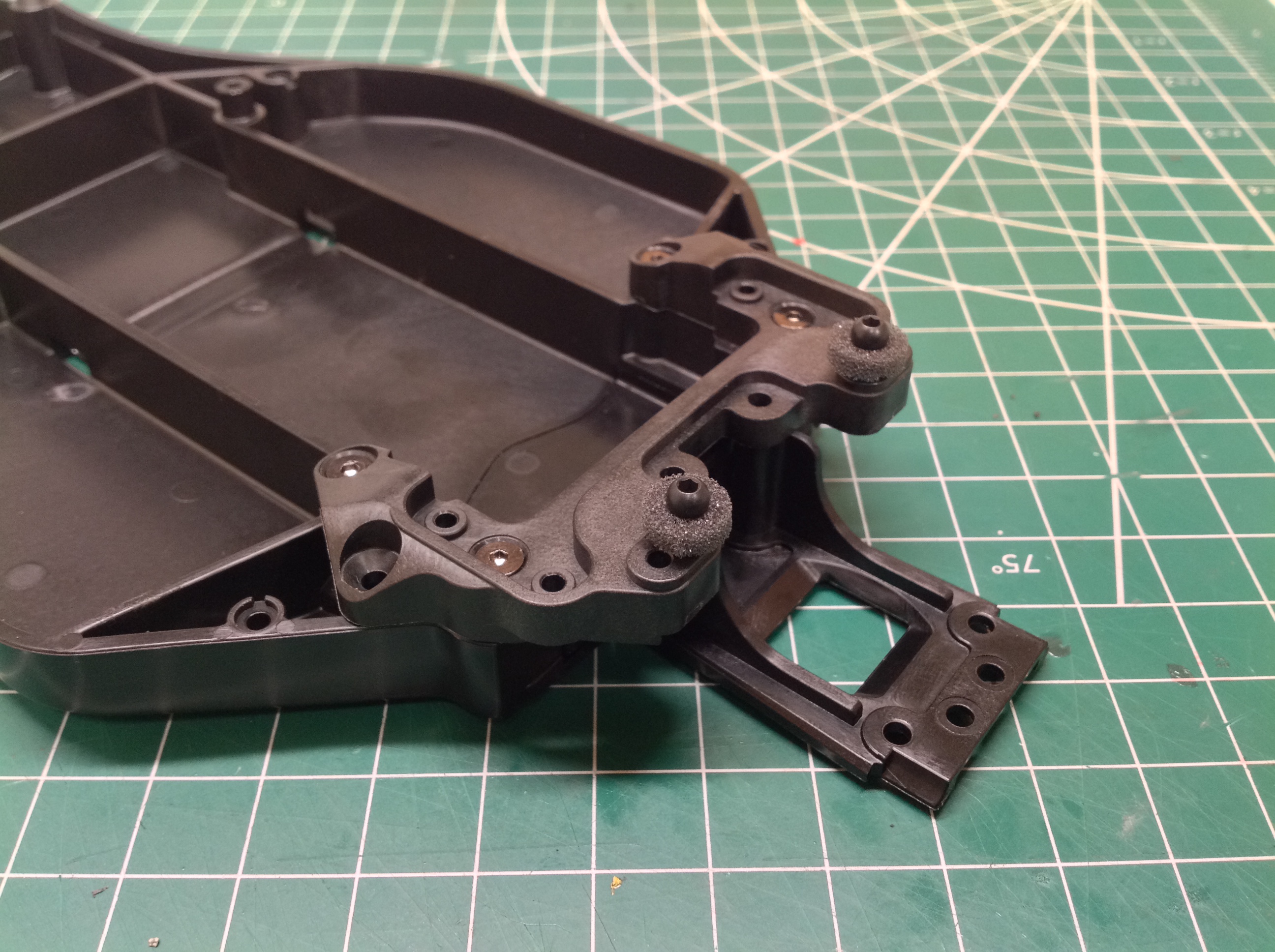
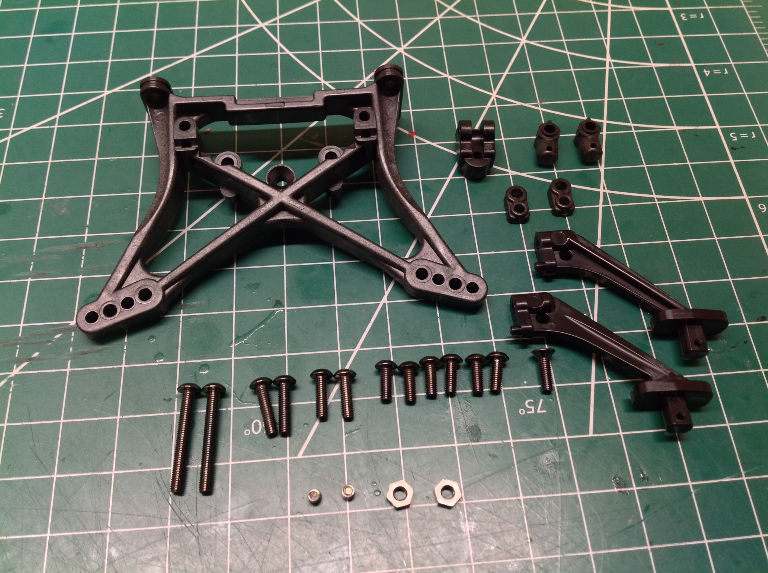
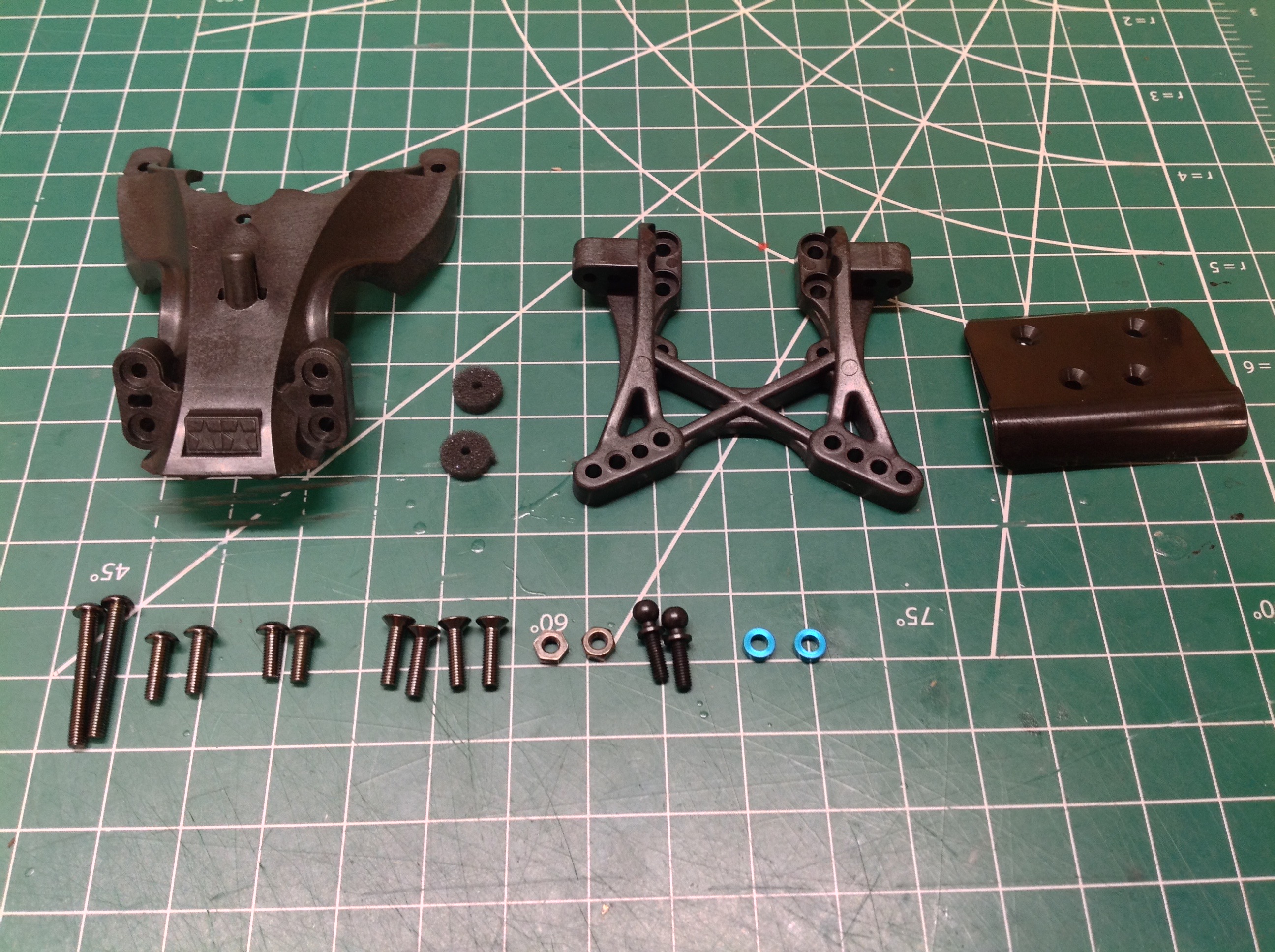
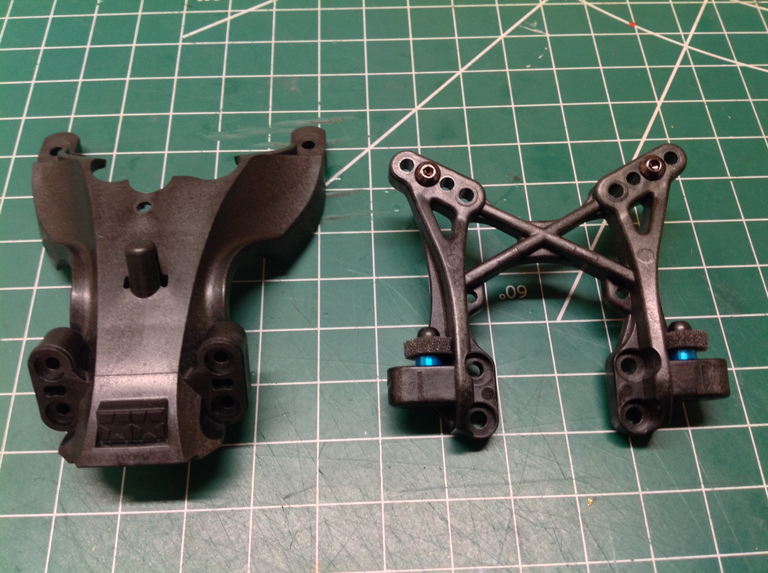
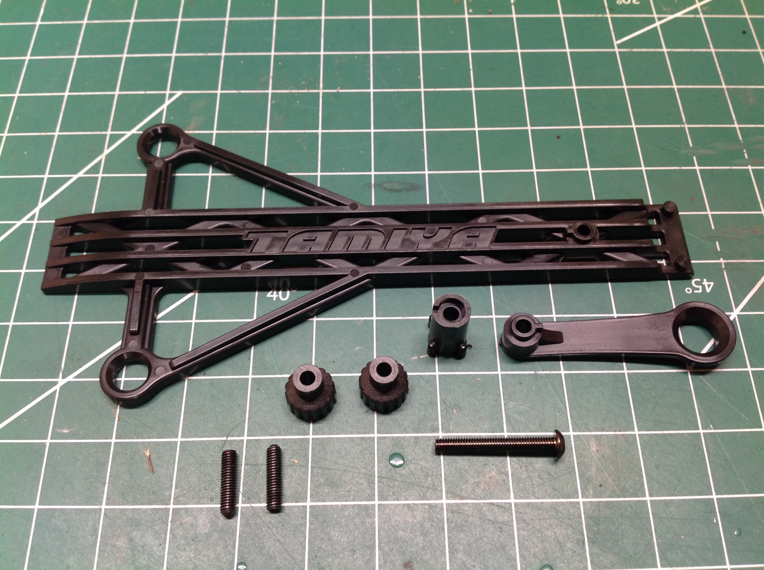
Step 12 is the rear shock tower, a huge cross braced plastic part.
The wing support brackets connect directly to the shock tower. In
the right hand picture you can see the unusual horizontal body posts
sticking out at rearward diagonals. You can also see that two of
the countersunk holes between the rear upper deck and the chassis are
empty. The manual never asks you to fill these holes.
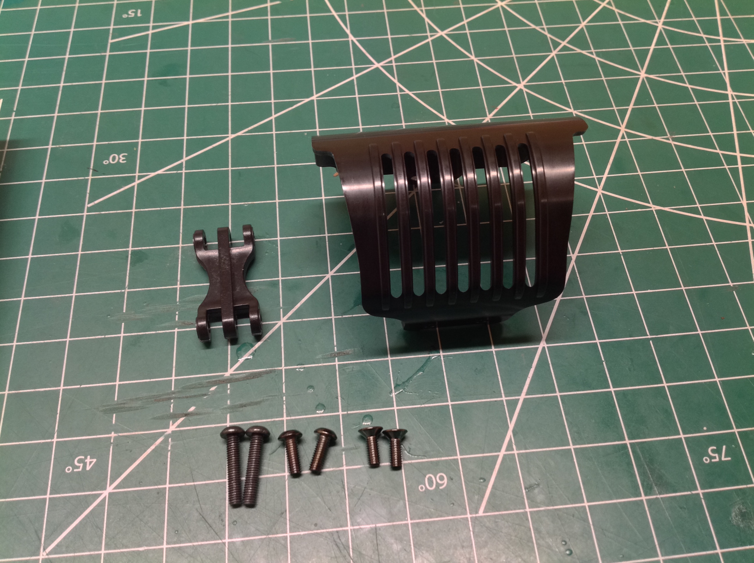
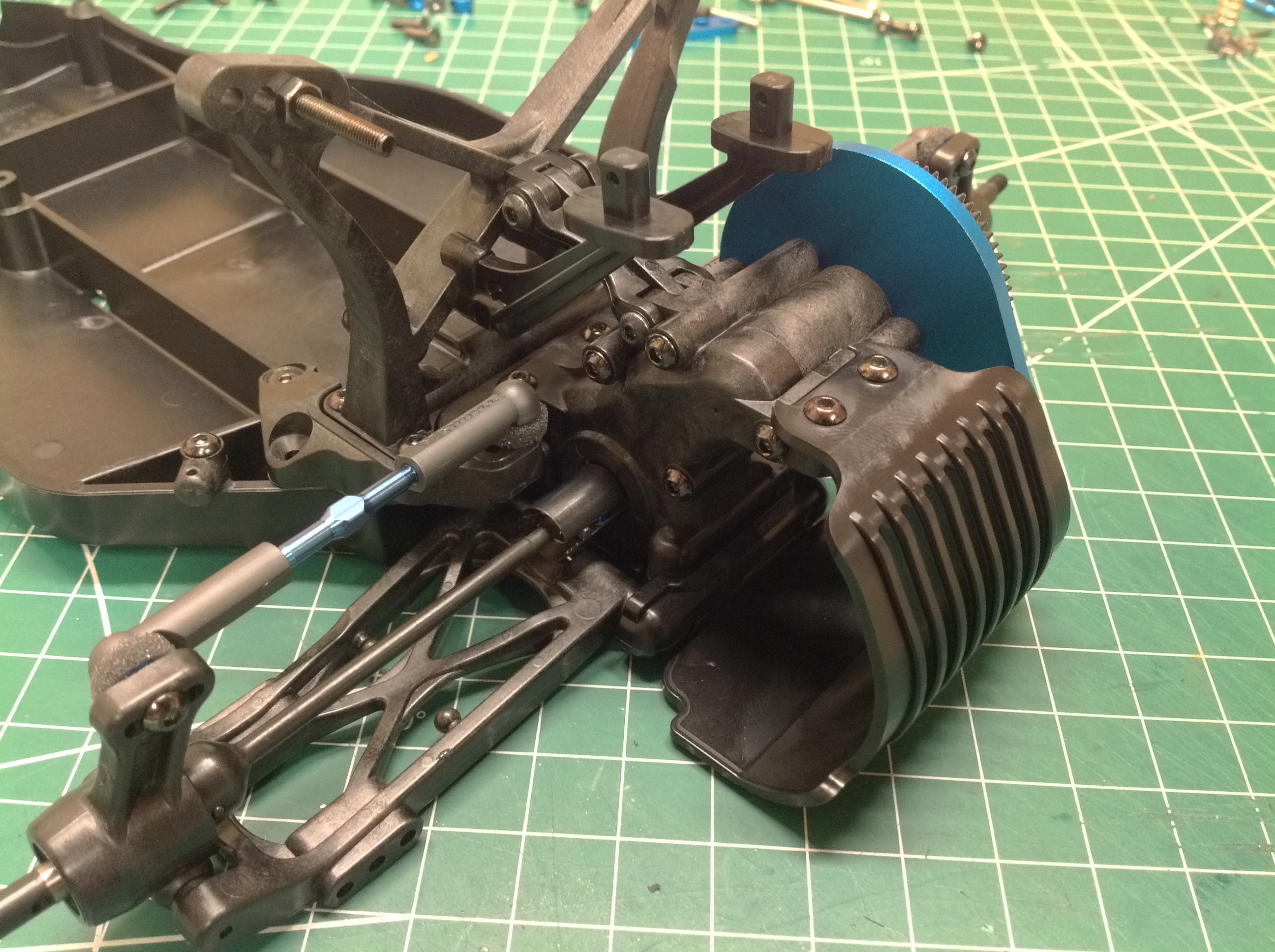
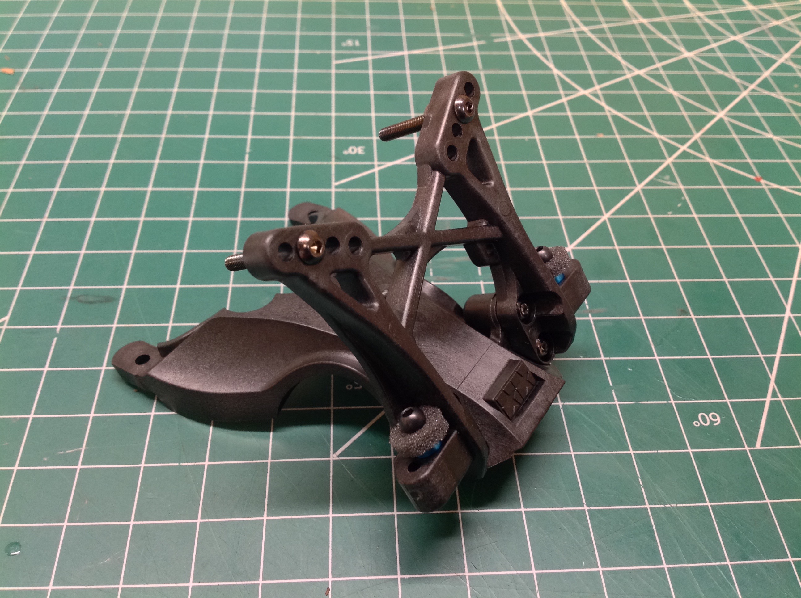
Step 13 installs the rear motor guard which also acts as a bumper and wraps around from the
bottom of the chassis to the top of the gearbox housing making it nice
and stiff. There is also a diagonal link which connects the
gearbox to the shock tower. I really like this detail. It
adds so much strength to the suspension.
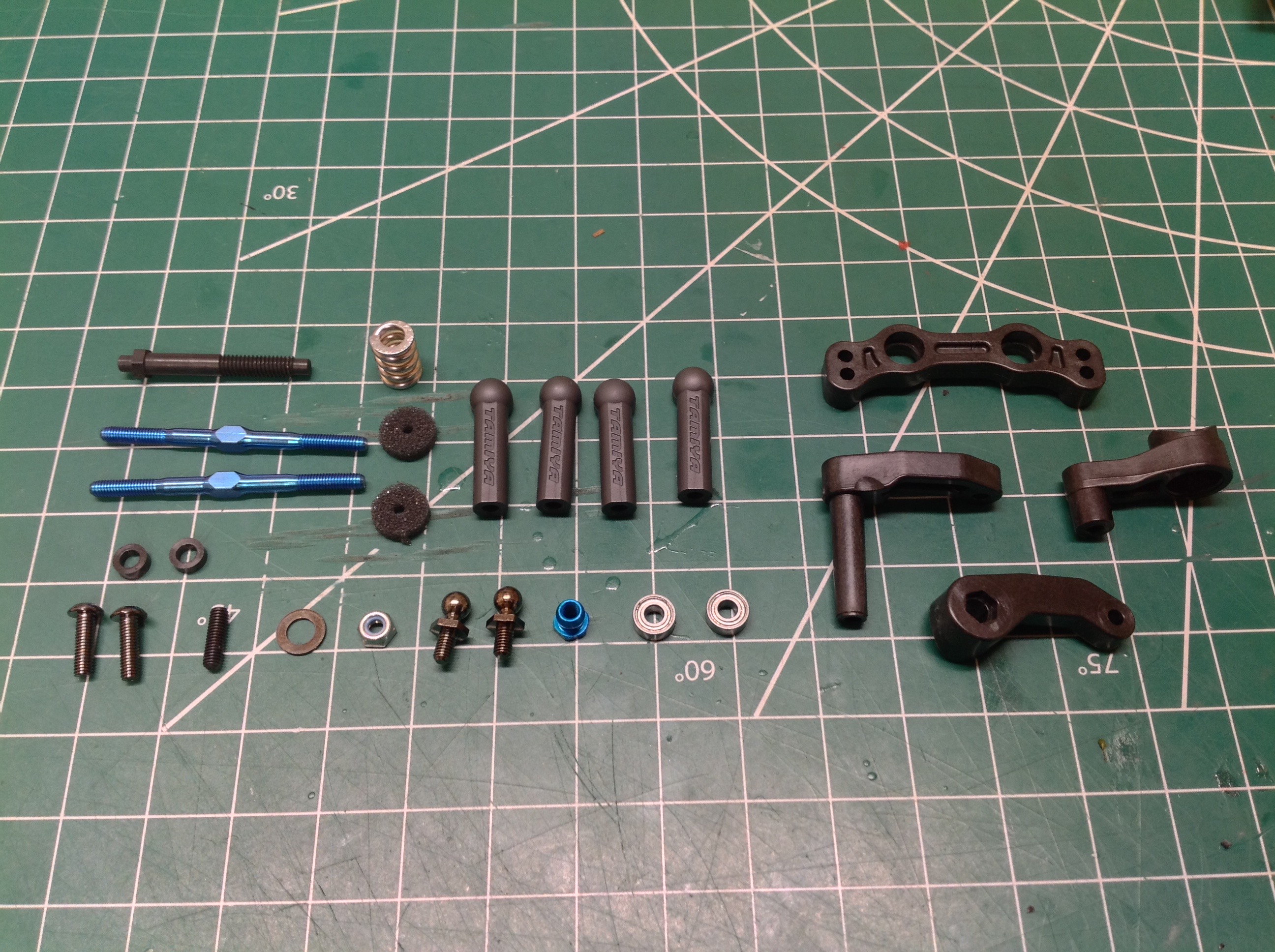
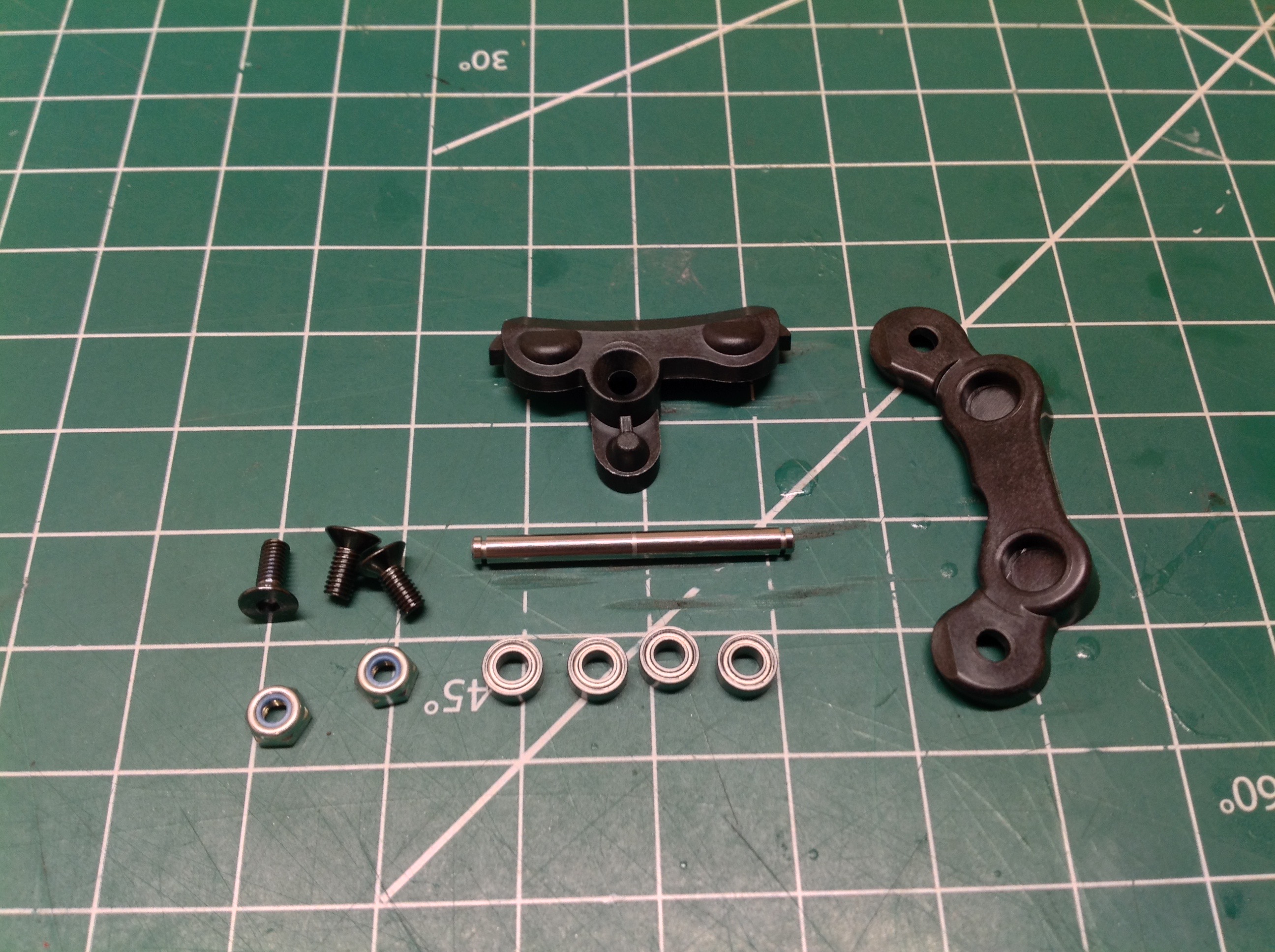
Step 14 builds the steering mechanism including dual bellcranks with
servo saver. These are hard carbon filled plastic parts with tiny
ball bearings (7x3mm). The fit and motion is very
precise with very little backlash. More titanium turnbuckles are
used as steering links.
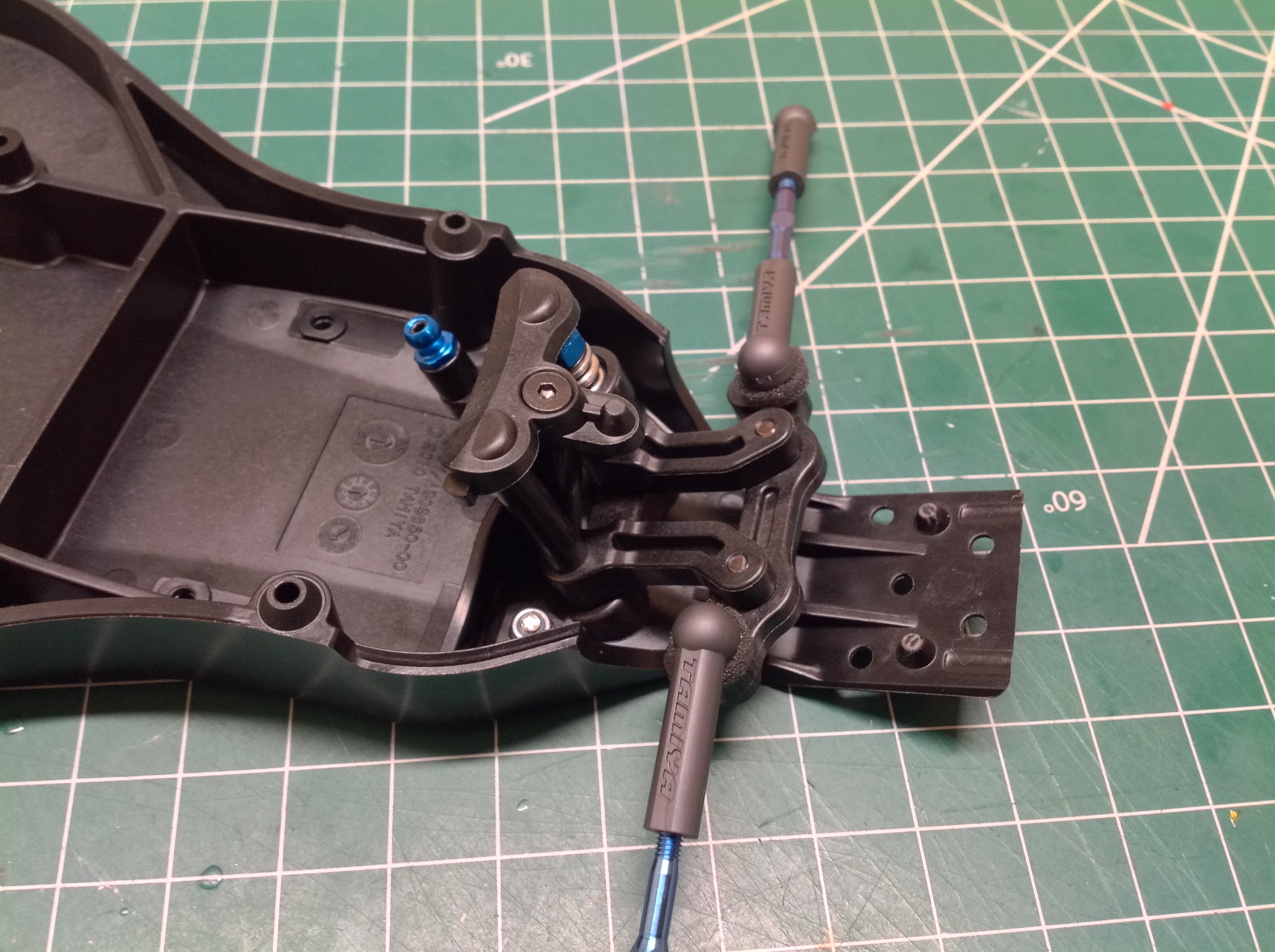
Step 15 installs the steering mechanism into the chassis using even
smaller bearings (6x3mm) and 3x33.4mm posts. Note how the whole
steering mechanism is tilted back to match the kick-up angle of the
chassis. While the bottom end of the pivots bolts directly to the
chassis, the upper end is somewhat floating in space, retained only by a
single countersunk screw on a post. The upper deck, once
installed, will grab the little conical pin forward of the screw, but
I'm surprised to see that this whole upper end of the mechanism wasn't
retained more firmly.
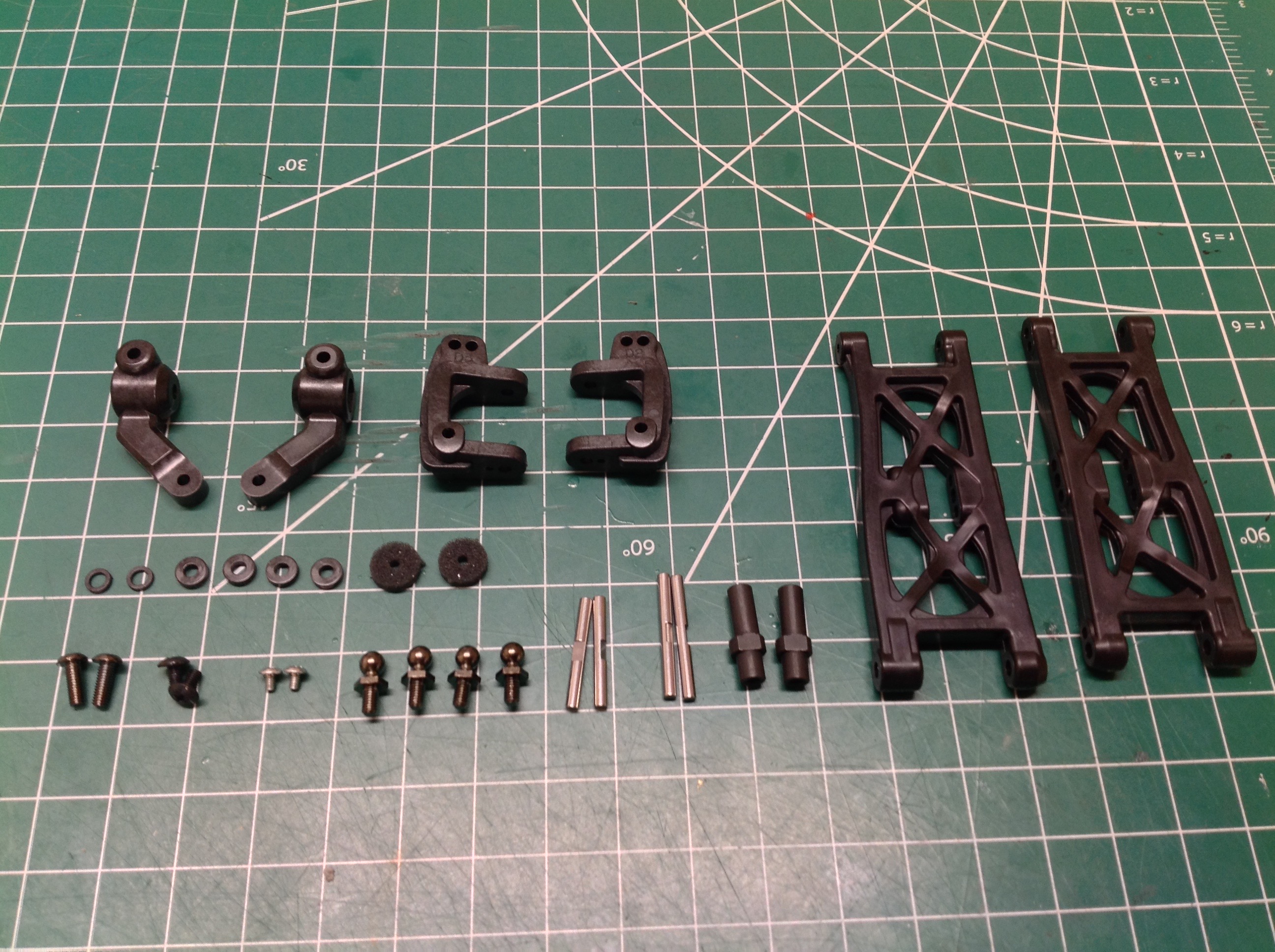
Step 16 attaches the C-hubs and steering knuckles to the front lower
suspension arms using quite a few parts as you can see on the
left. The steel axles are separate parts which fit into the
knuckles and are fastened from the back side. The axles have a very slight
asymmetry which it is easy to miss (and in fact I did miss it).
The effect of this asymmetry is movement of the front wheel very
slightly forward from the center of the knuckle. If you look very
closely at the right hand axle in the right hand picture you can detect
that the long end is not perfectly aligned with the short end.
Now the knuckles can be installed into the C-hubs. Instead of
using separate upper and lower kingpins, this kit uses a single vertical
2.6x22mm shaft which provides a very smooth steering axis. The
hub then connects to the arm with a 2.6x25mm shaft and a couple of
spacers for centering. The wheelbase could be altered slightly by
changing the configuration of these spacers.
Step 17 attaches the front arms to a center bulkhead. It is
interesting that this bulkhead is a separate part which means the arms
do not pivot directly from the chassis. The arms are attached to
the bulkhead with 3x35mm shafts and retained by an aluminum front plate.
Step 18 bolts the self contained front suspension assembly to the
chassis plate with a single countersunk screw installed from
below. This is as simple as steps get.
Step 19 builds and installs the front shock tower (which Tamiya calls a
damper stay) and upper deck. The deck includes a bit of support
for the steering cranks, a front body post, and structural support for
the shock tower. These are both very hard carbon filled
parts. We even get a little Tamiya logo visible from the
front. We start by installing some spacers, ball connectors, and
dust covers to the shock tower along with some long 3x23mm screws for
the shocks.
Now the shock tower can be bolted to the upper deck with 4 screws.
Finally, this entire assembly is connected to the chassis to complete
the front suspension. At this point both the upper suspension
links and the steering links are connected. There is also a tiny
(almost invisible) front bumper protecting the bottom of the chassis
tub.
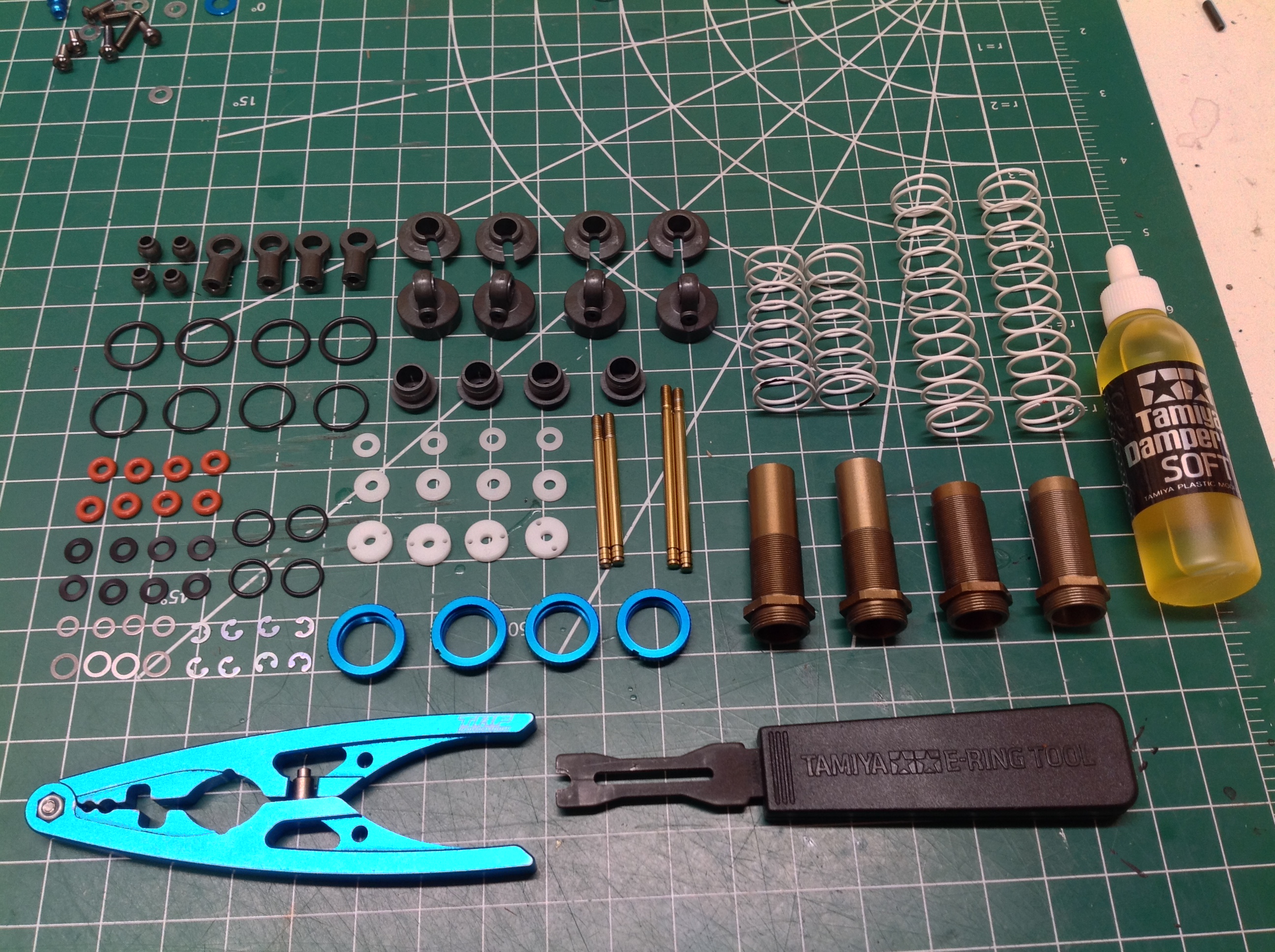
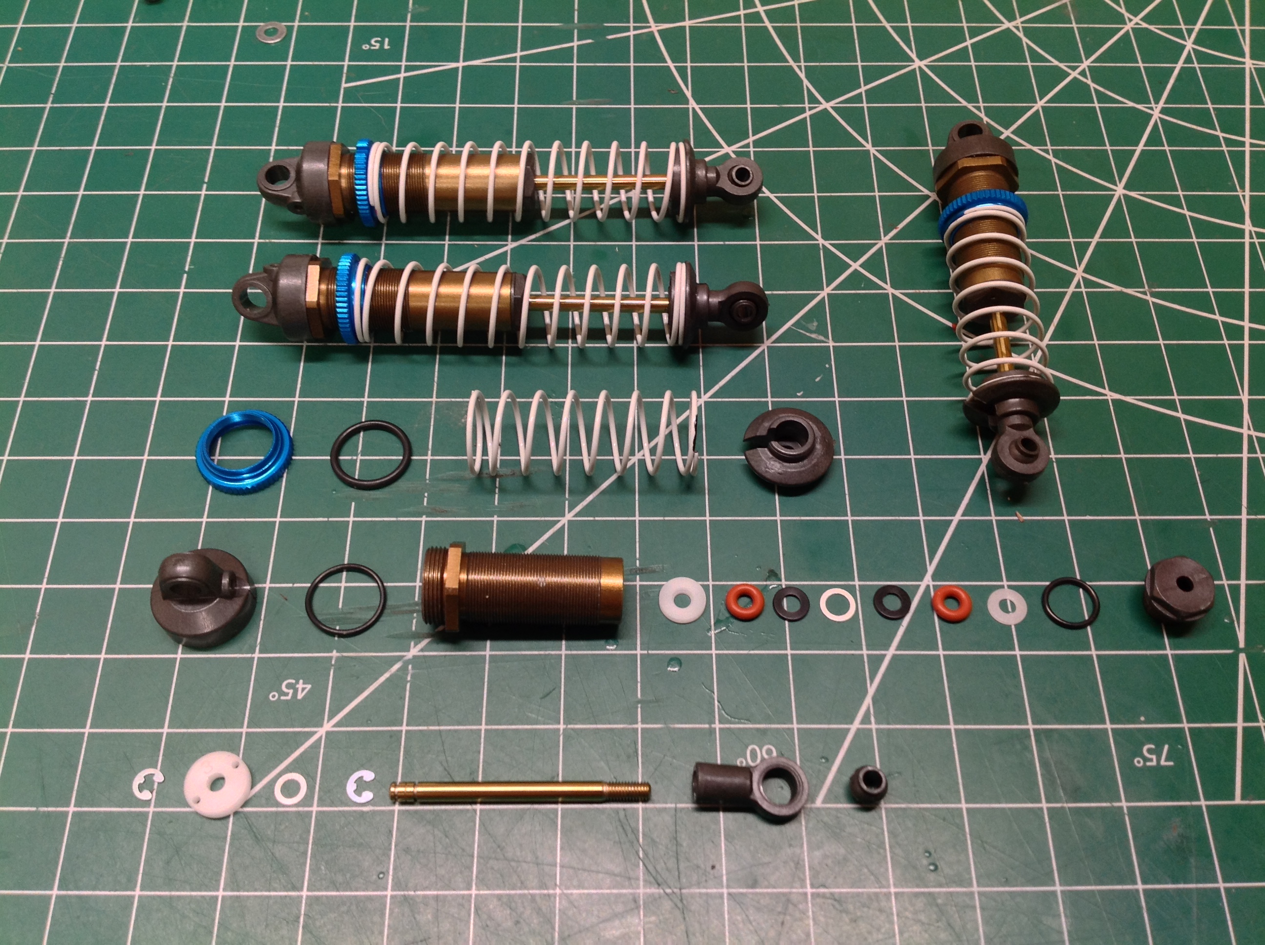
Step 20 opens hardware bag C which contains the parts for the standard
TRF buggy shocks. The all aluminum shocks have a 10mm bore and a
lot of parts as you can see. The complete assortment of parts is
shown on the left. On the right you can see three completed shocks
along with an exploded view of the fourth. The kits comes with
two sets of pistons, one with 1.3mm holes and one with 1.4mm
holes. I certainly wouldn't be able to discern the difference
between these two, but I tend to like softer suspension so I chose the
larger holes. Note that these are emulsion shocks which don't use a
bladder. Instead, air is removed through a bleed screw in the
head end cap with the shock retracted. The results in a void when
the shock is extended. Shock assembly continues into Step 21 which
adds the oil and bleed procedures.
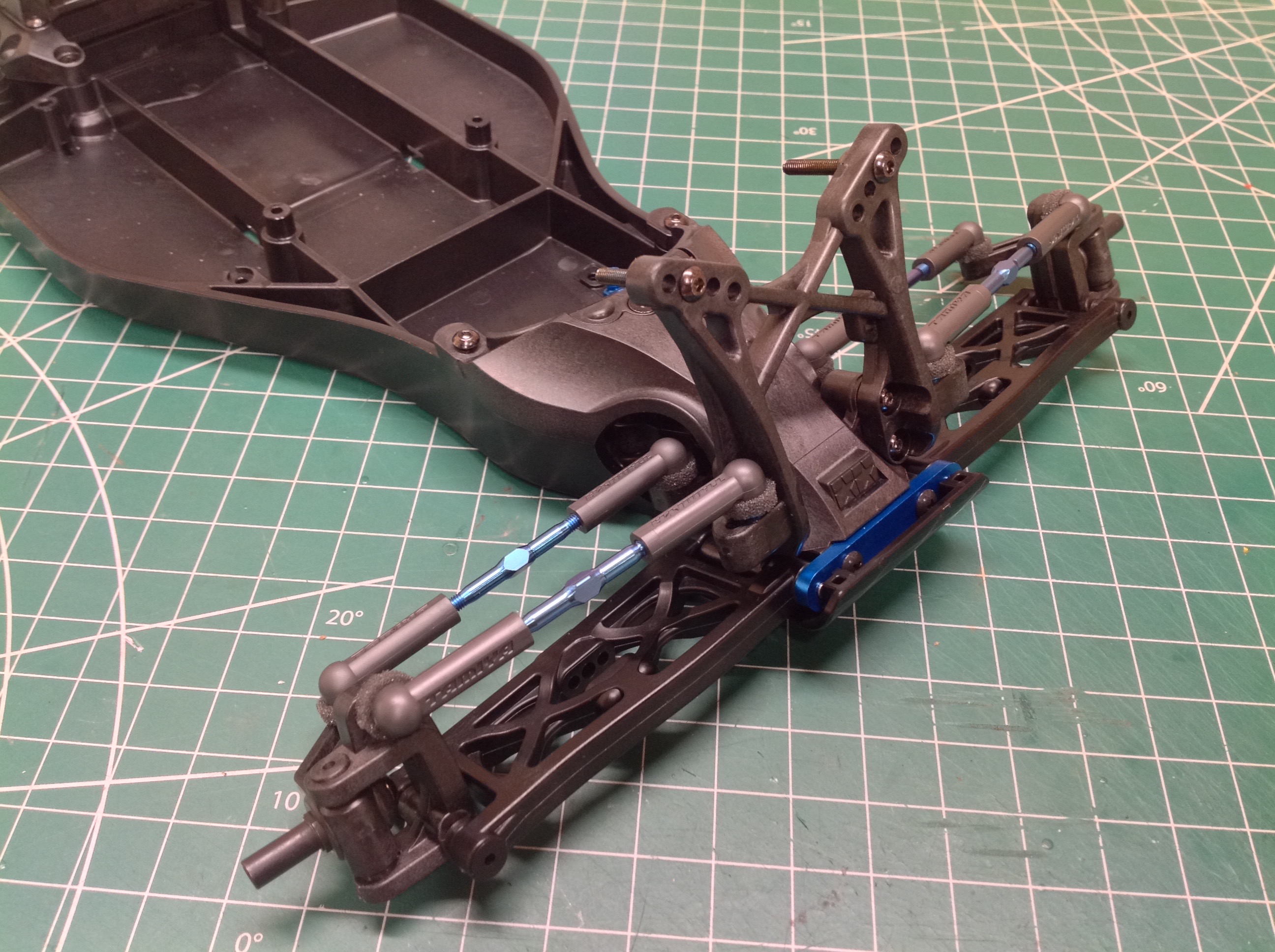
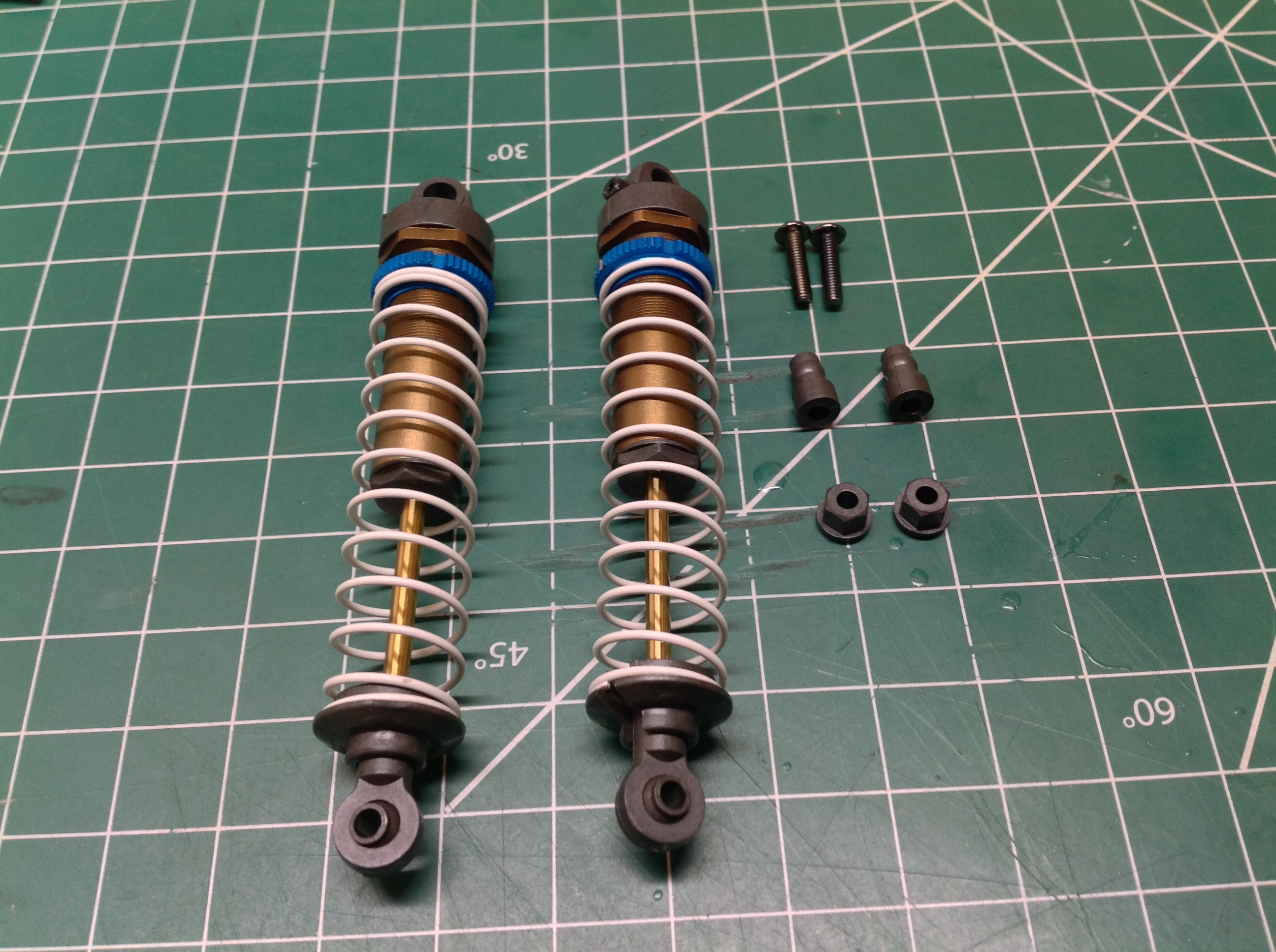
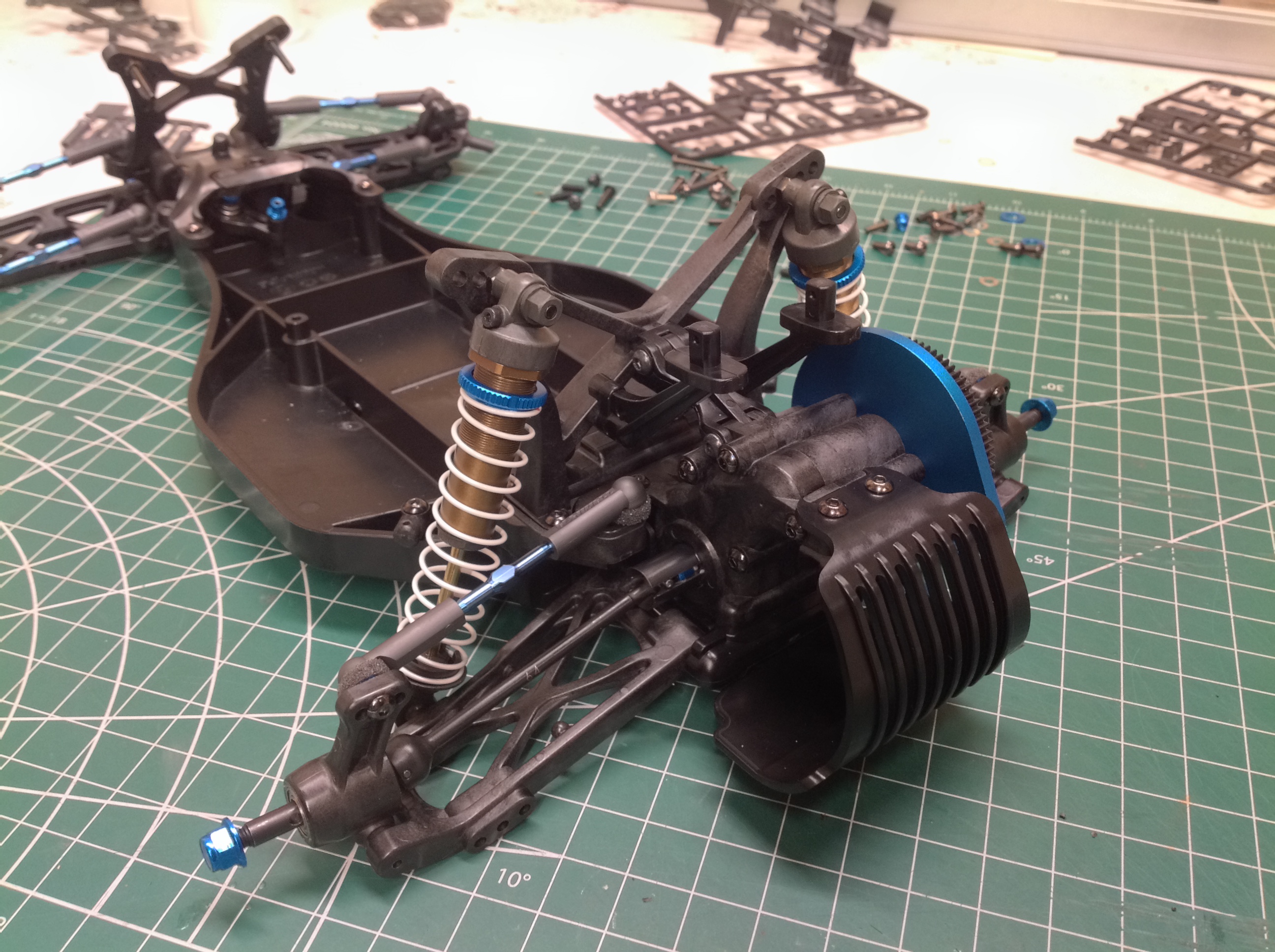
Step 22 installs the completed rear dampers behind the rear shock tower
but ahead of the rear suspension as shown. Special joints are used
at the top to allow spherical rotation without a ball joint.
There's also a plastic retention nut here. I assume this is to
prevent over tightening which would crush the joint.
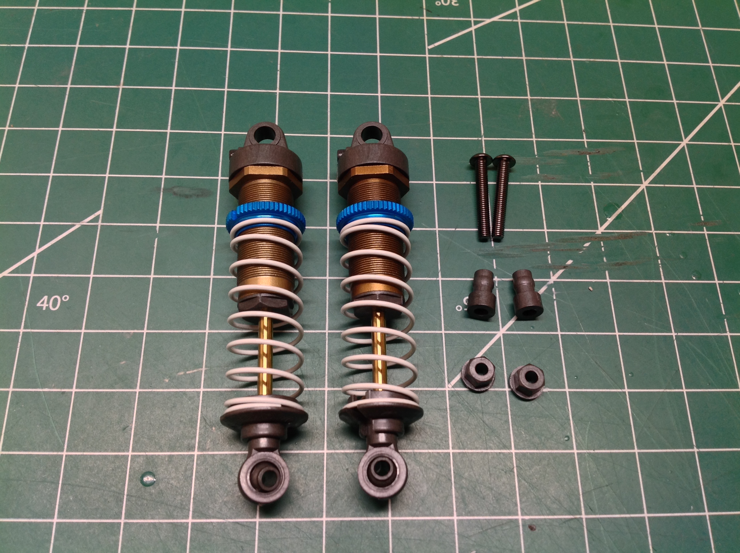
The shorter front shocks are installed in Step 23 using the same
procedure as the rear. There is a difference in lower attachment
point as shown on the right. The rod end sits in a slot in the
middle of the lower suspension arm.
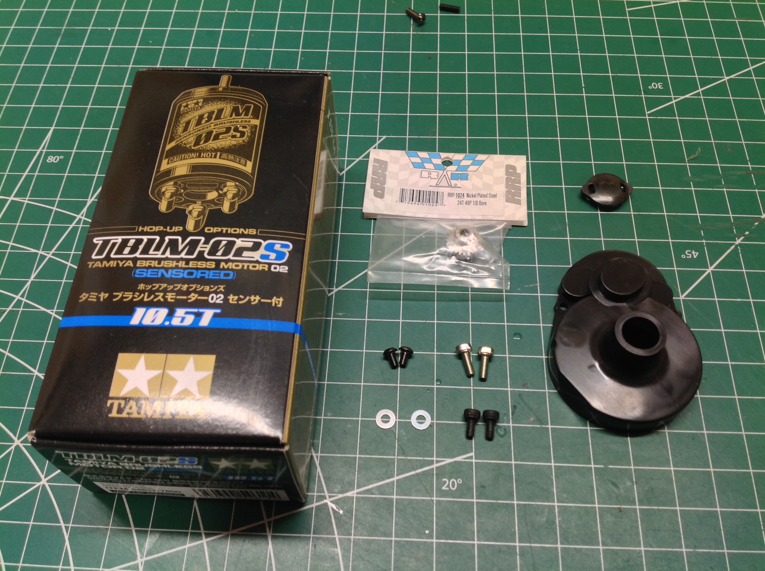
I had a Tamiya brushless system saved for just this occasion. At
one point I had a pair of TBLE-03s controllers in my TXT-2 but they
don't work well in pairs and I burned one out. I saved the good
one for a worthy cause and this was it. I combined it with a
TBLM-02s 10.5 turn sensored motor and a 25 tooth steel pinion
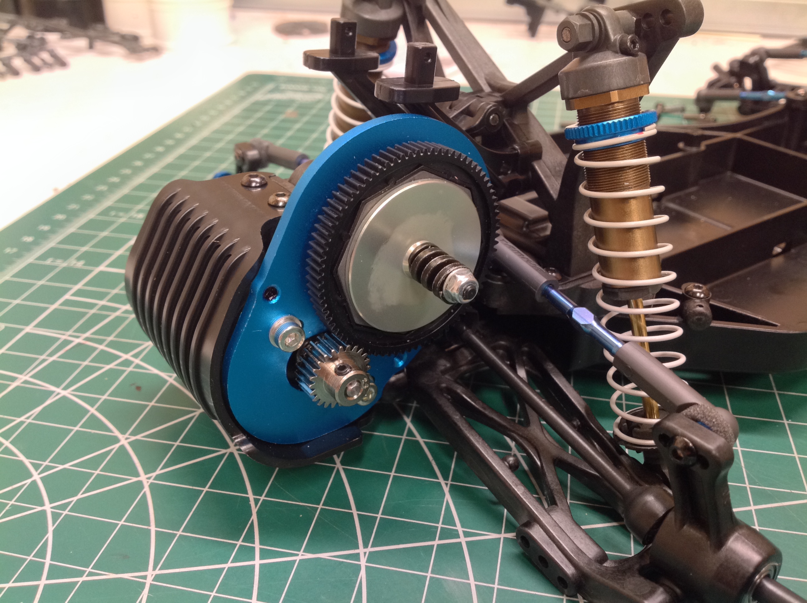
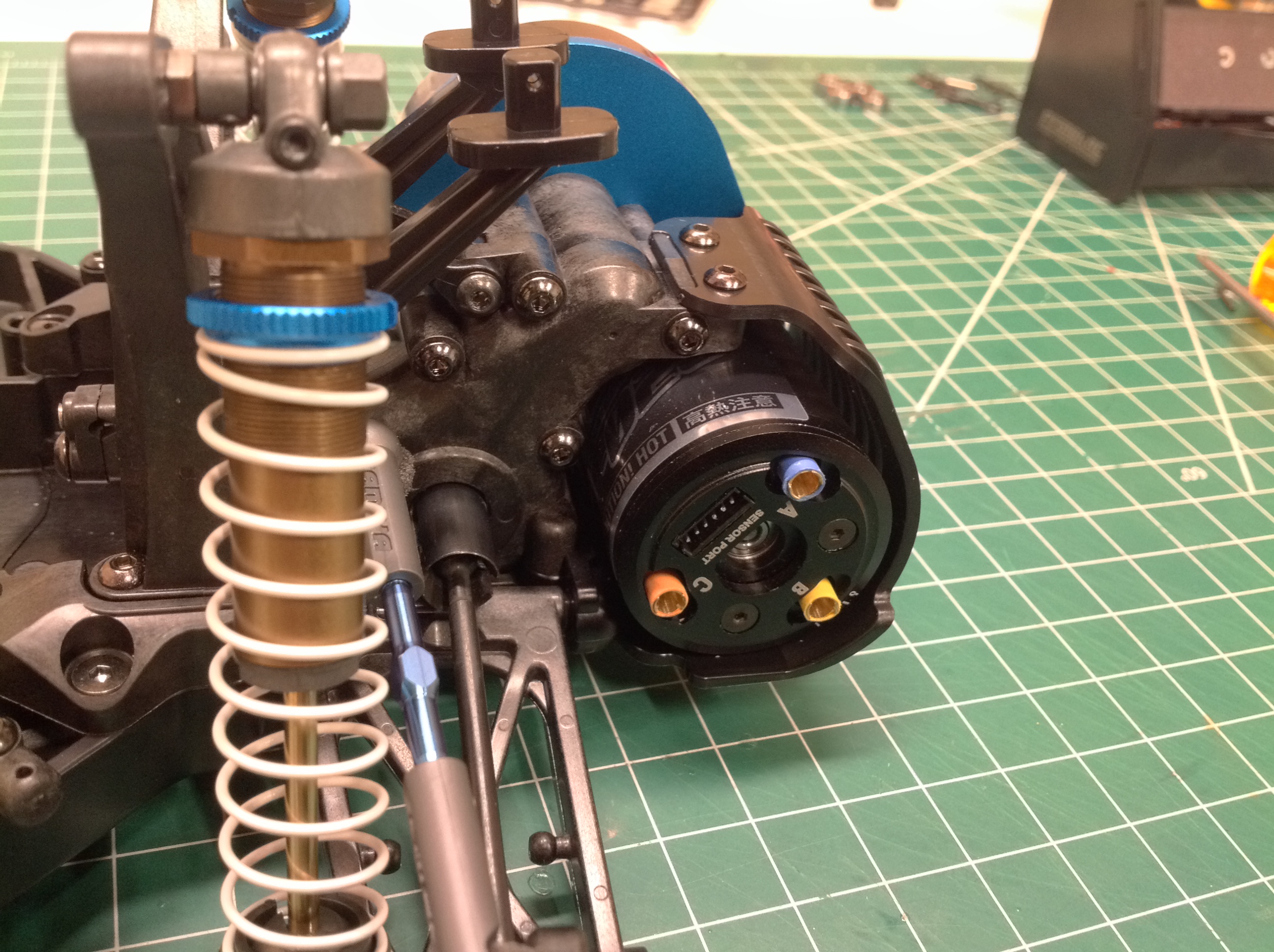
gear. Step 24 installs the motor onto the chassis. As
previously mentioned, this chassis uses 48p drive gears.
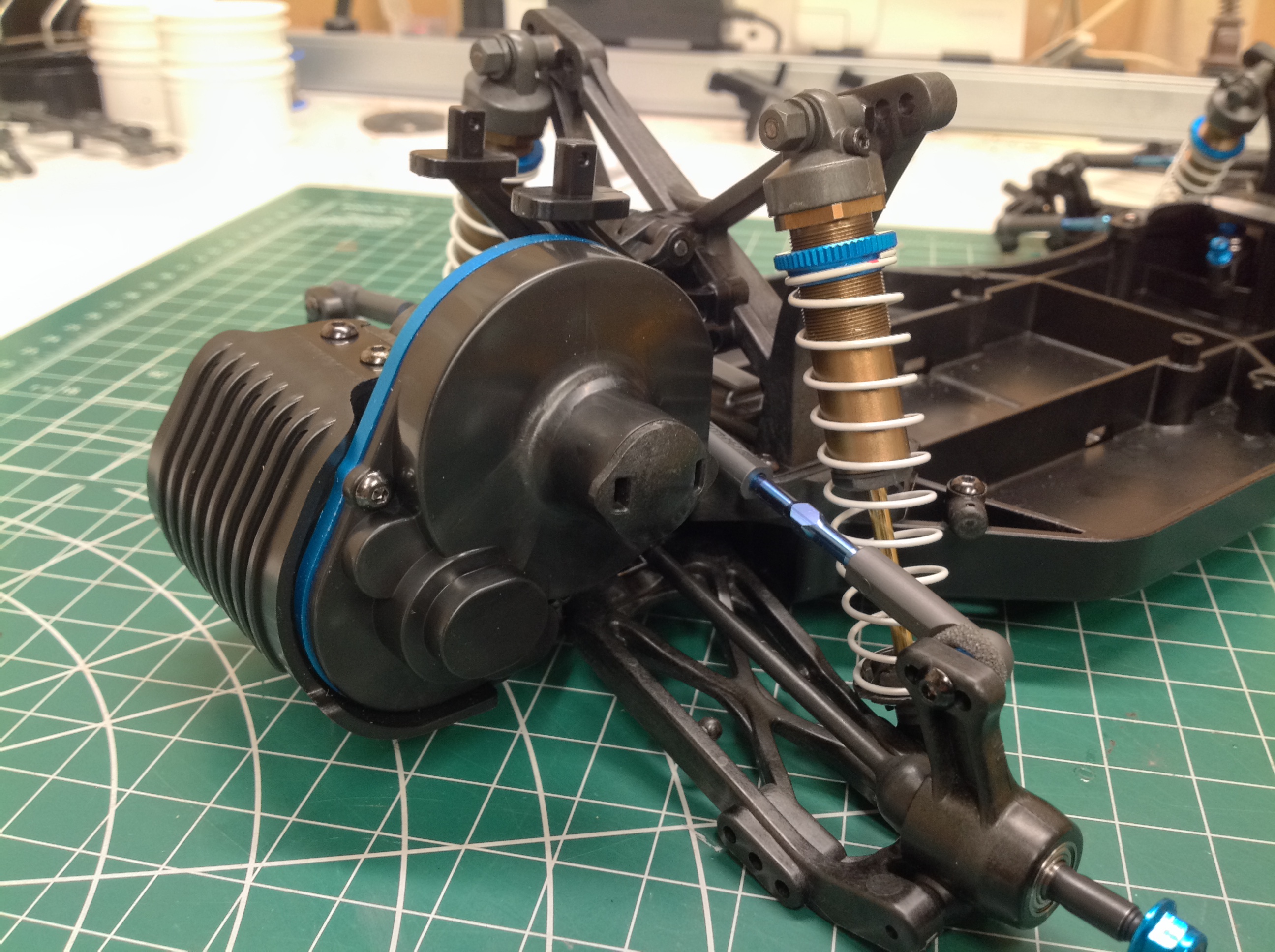
The gear cover is soft plastic and includes a removable cap to
access the adjustment nut for the slipper clutch. Many brushless
motors have tabs onto which you must solder the wires which requires
that the motor be oriented in a specific way to avoid interference with
other parts. Tamiya brushless motors have colored 4mm bullet taps
in the end face so orientation isn't important.
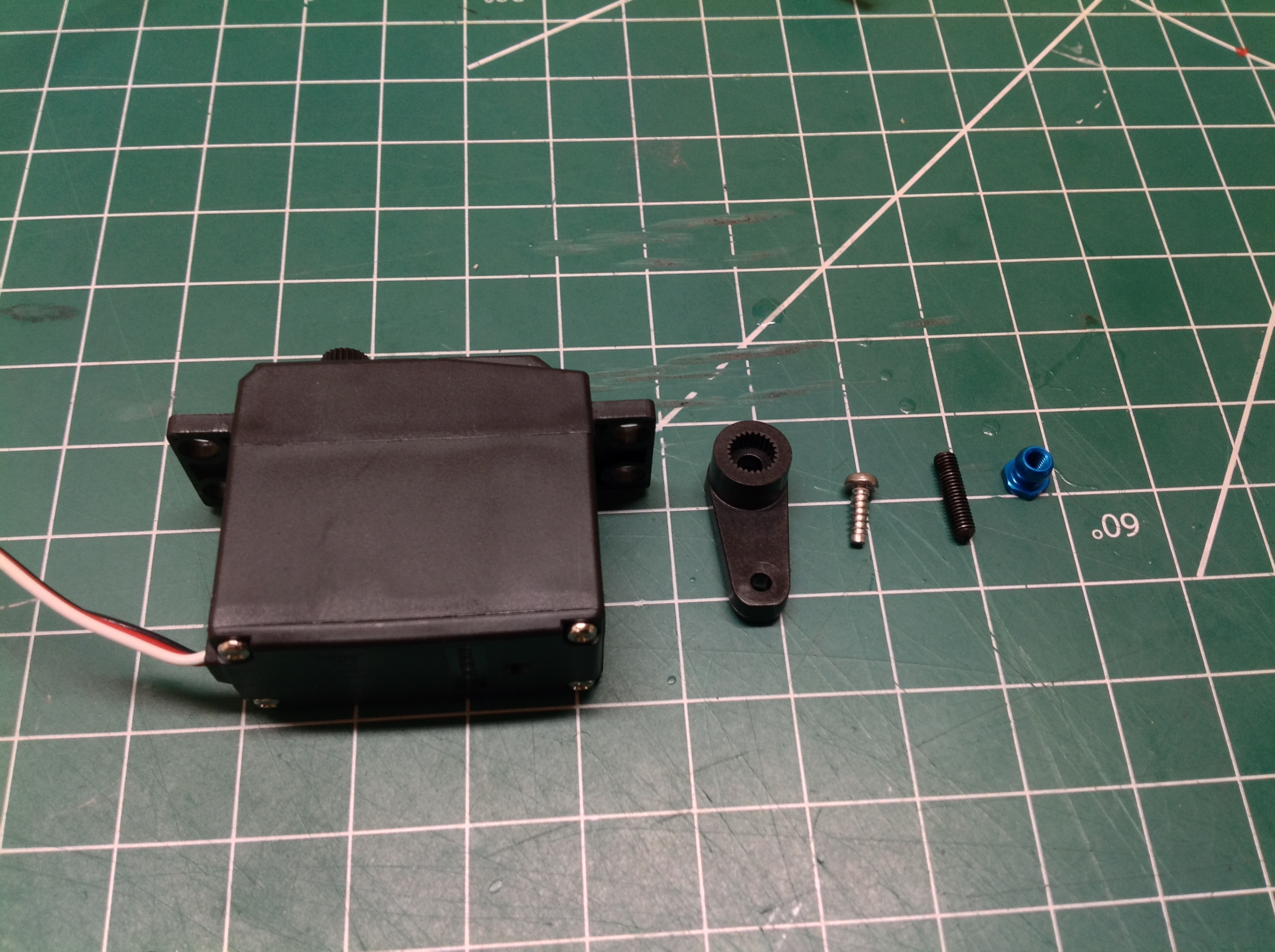
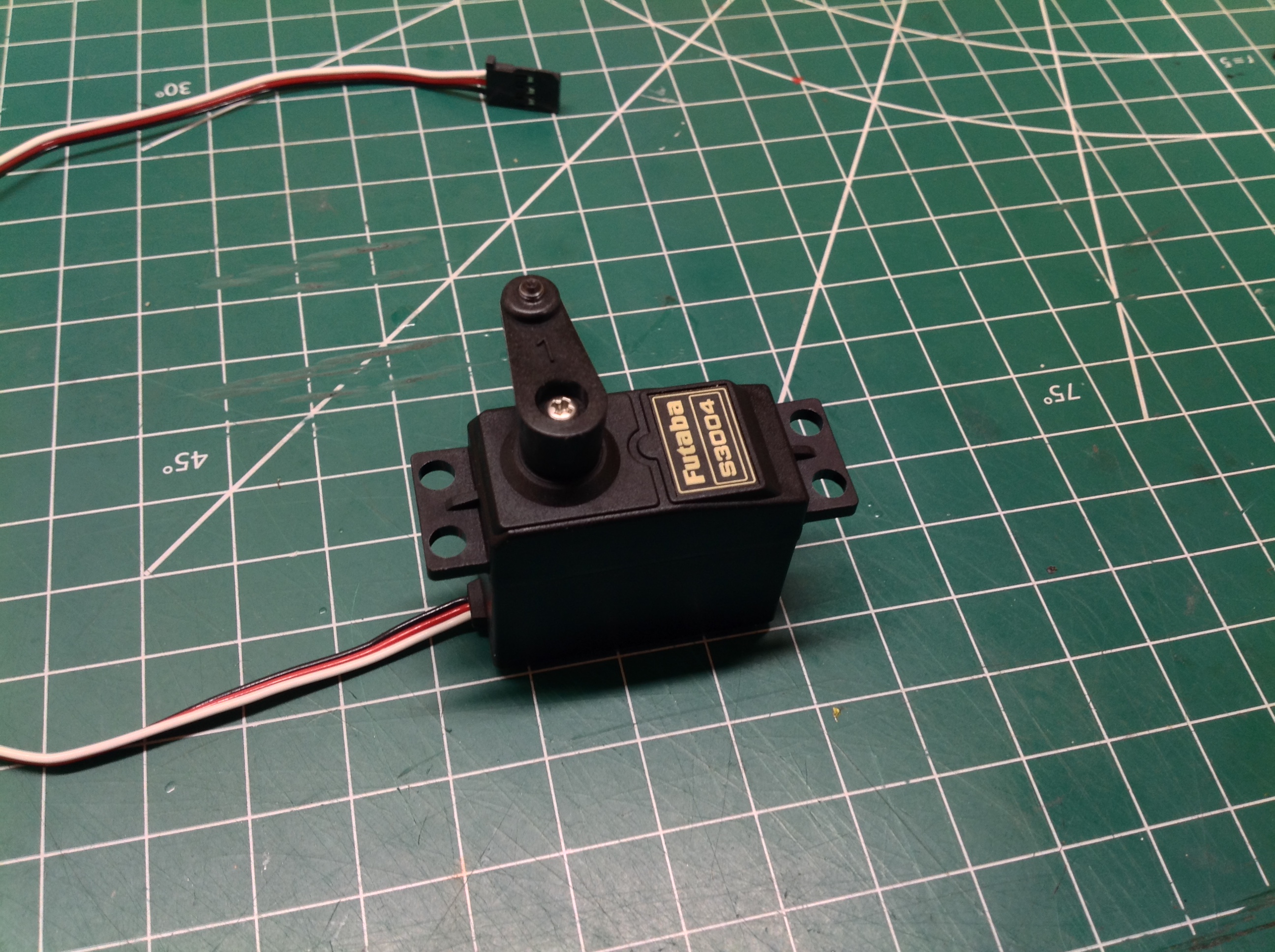
Step 25 does no more than attach a servo horn to the steering
servo. The kit comes with two servo horns: one with 24 teeth and
one with 25 teeth. The cheap Futaba servo you see here is just a
placeholder until the correct servo arrives. I got a low profile
Savox servo that would work well with all three chassis variations.
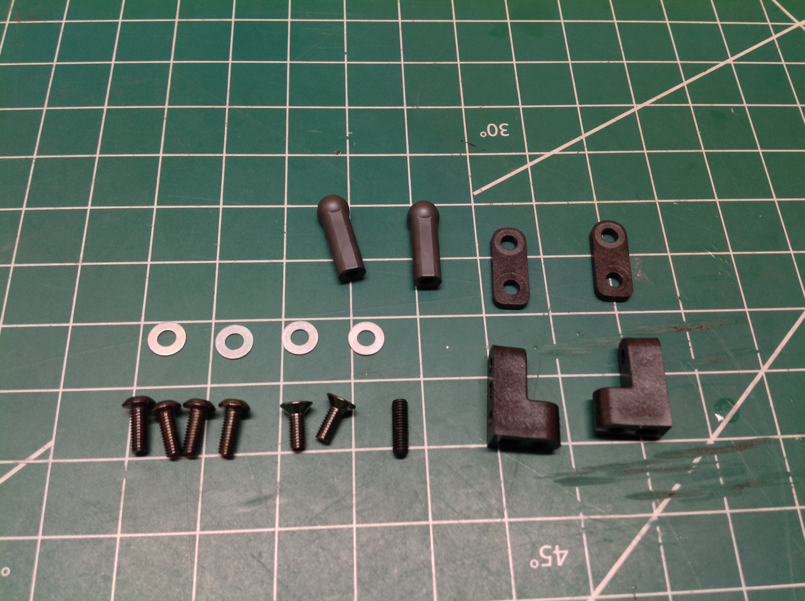
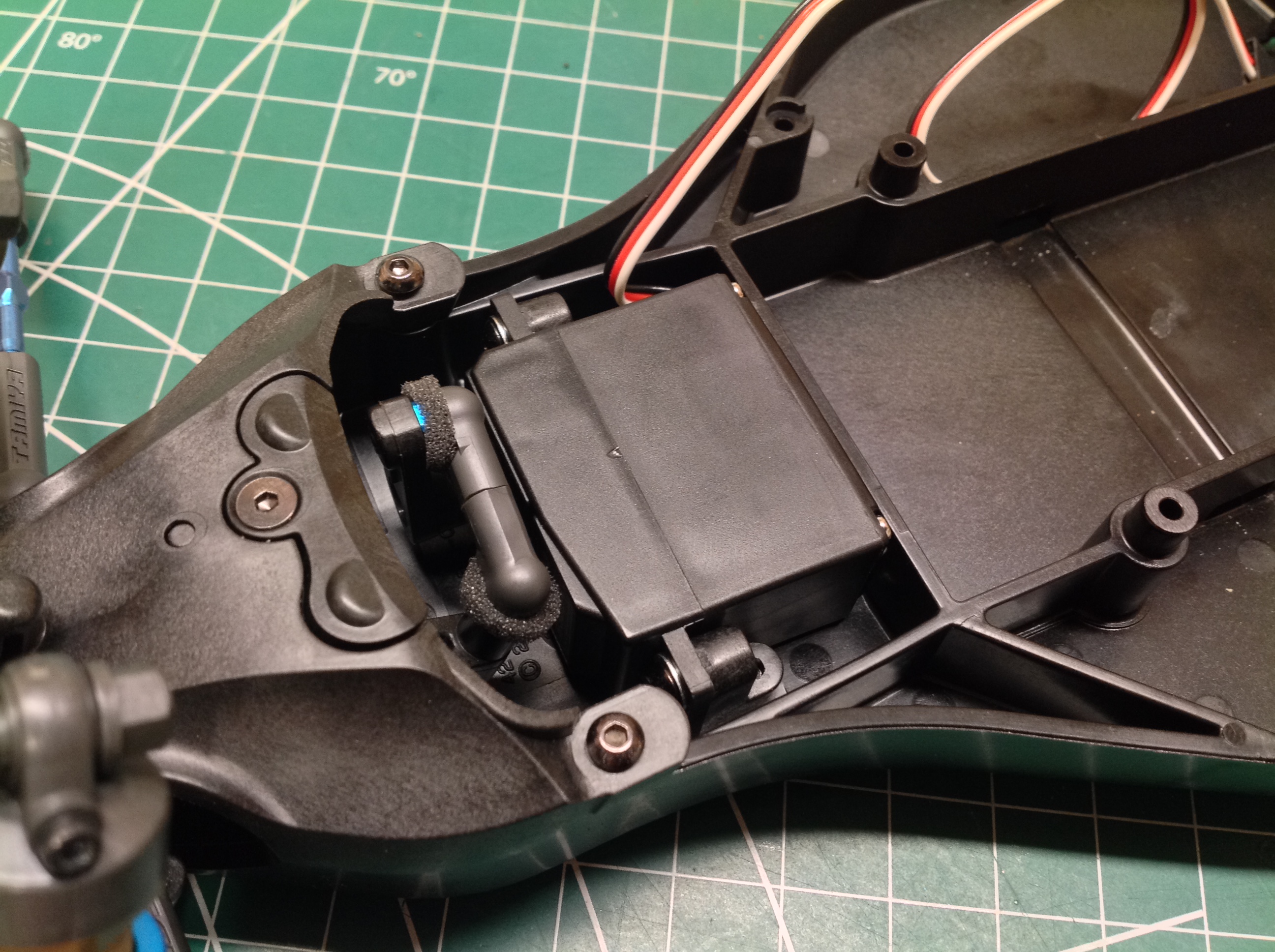
Step 26 installs the steering servo in the chassis. Most Tamiya
kits use only two screws to mount the servo to the attach brackets, but
this kit uses four. Another two countersunk screws attach the
brackets to the chassis tub. The steering link is very short and
requires you to cut two ball ends to make them short enough to work.
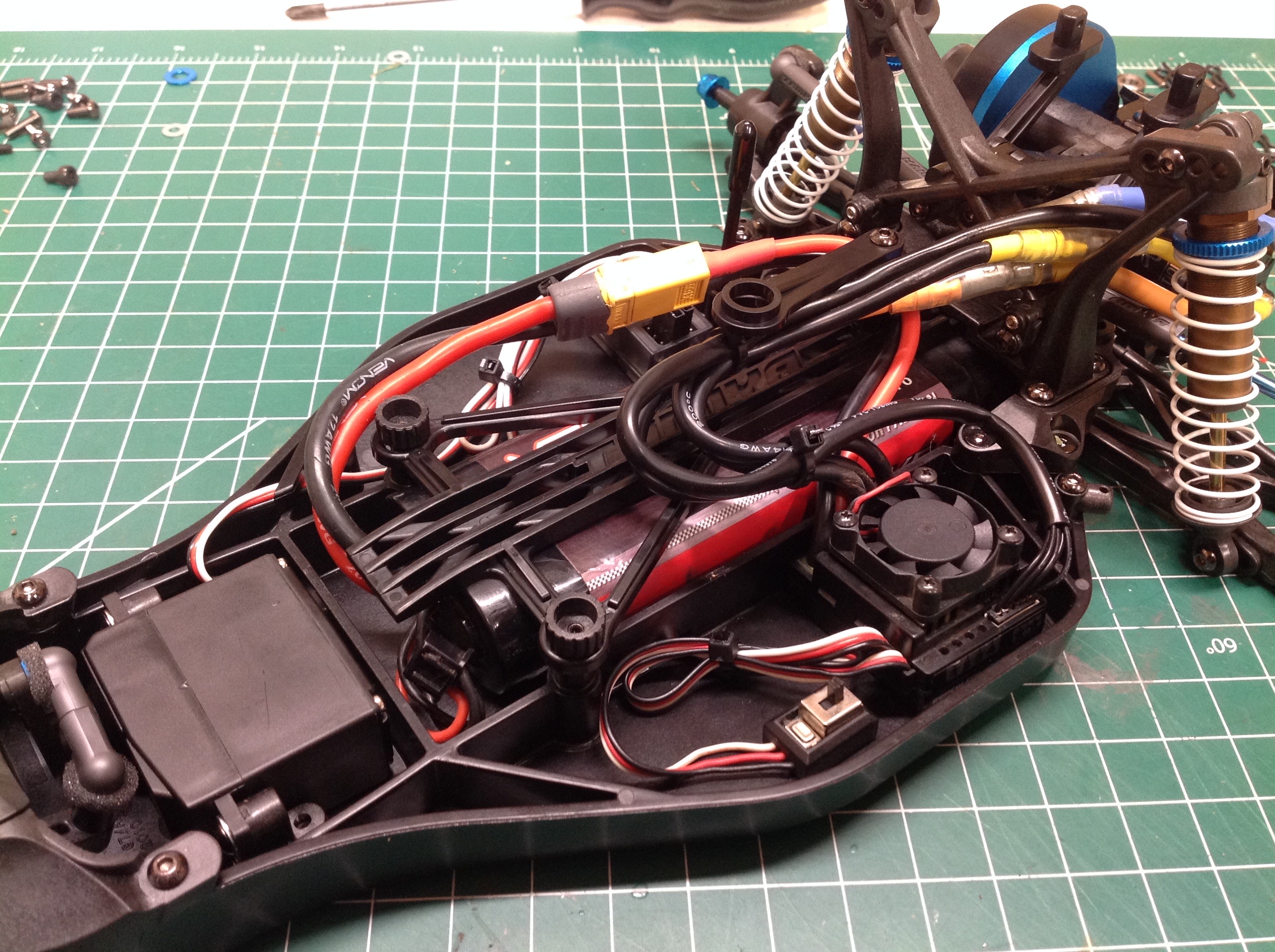
These pictures combine Steps 27 and 30. Step 27 shows you how to
install the electronics. I put the ESC on the left and the
receiver on the right. There is plenty of room to spare. The
battery area runs down the center of the chassis and will accept a NiMH
stick pack or a hard racing LiPo pack. Step 30 builds the battery
holder from the parts shown on the left. A pair of thumbscrews
hold it in place. There is a transponder mount as well.
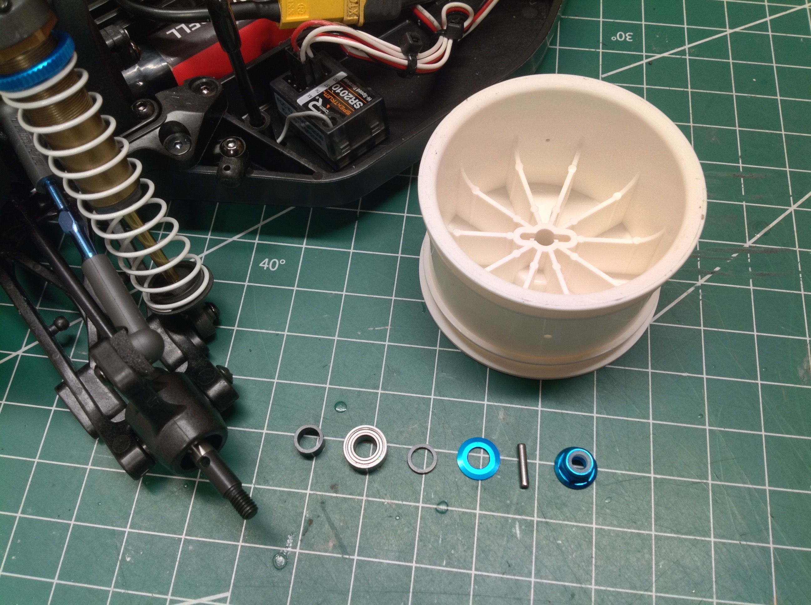
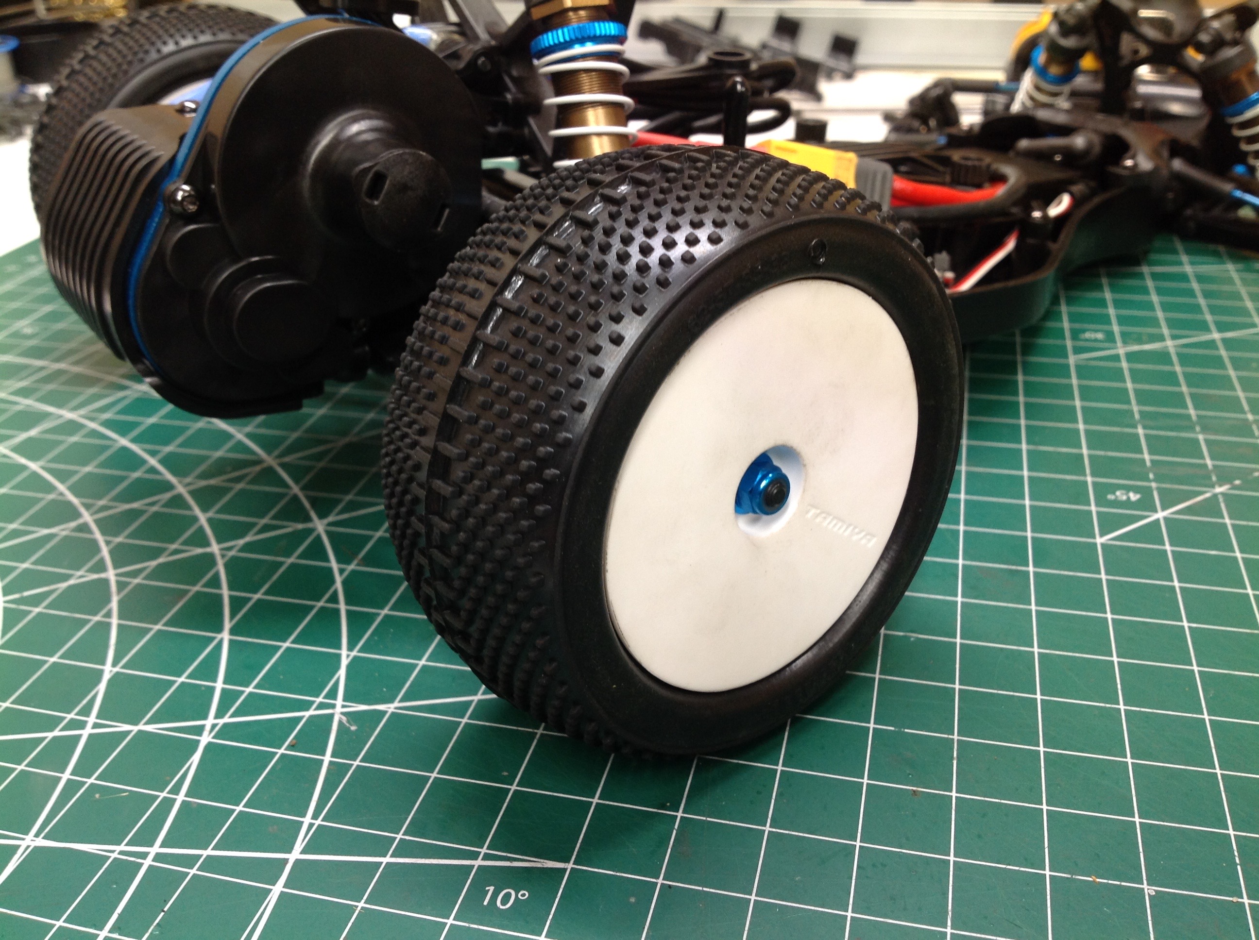
Both the front and rear wheels attach in unusual ways. These
pictures show the installation of the rear wheels. There is no
12mm hex, instead the drive pin mates directly with the inside of the
wheel as shown. There are also some spacers and washers which sit
behind the wheel to make it fit tightly with no lateral slop.
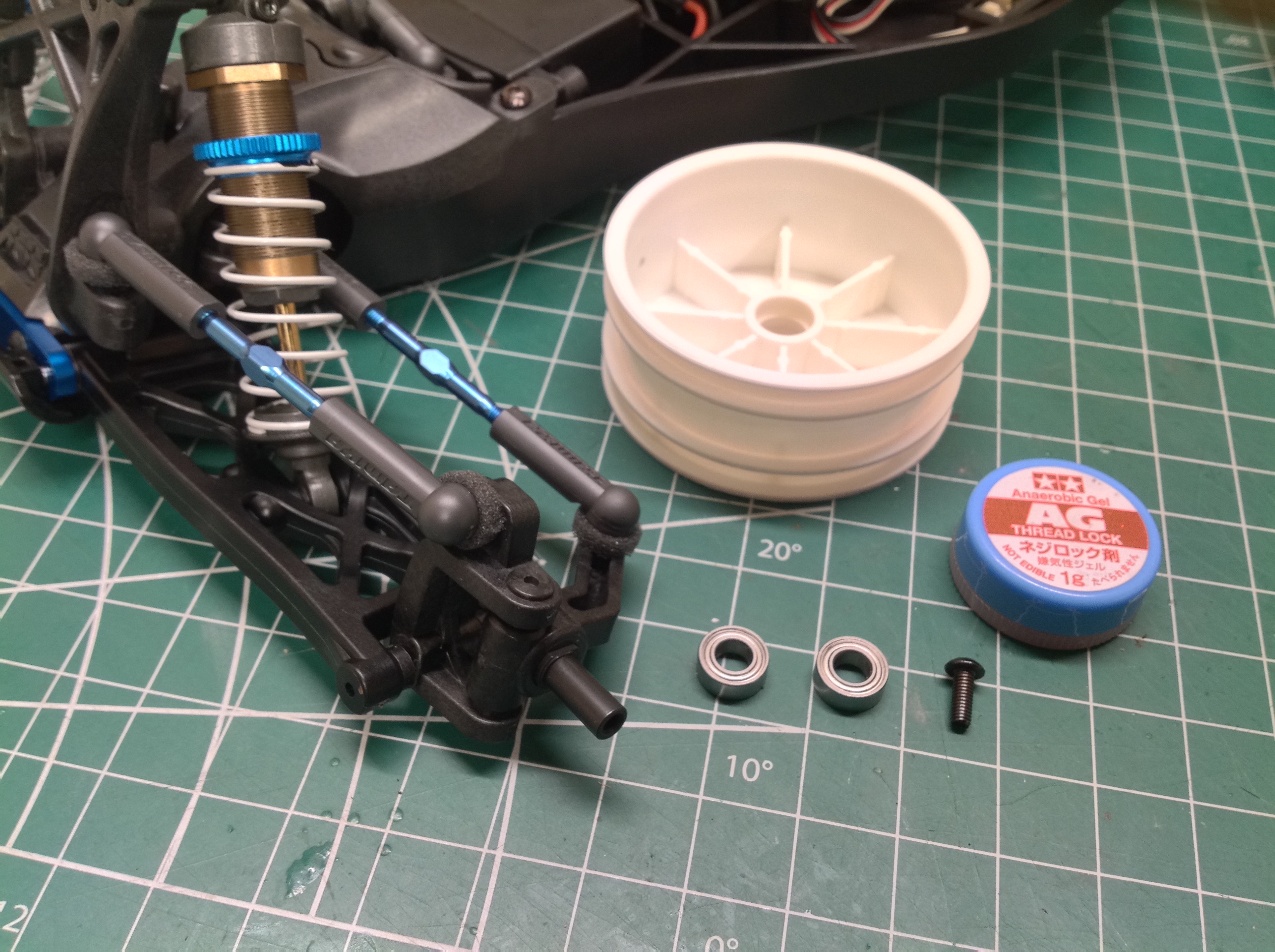
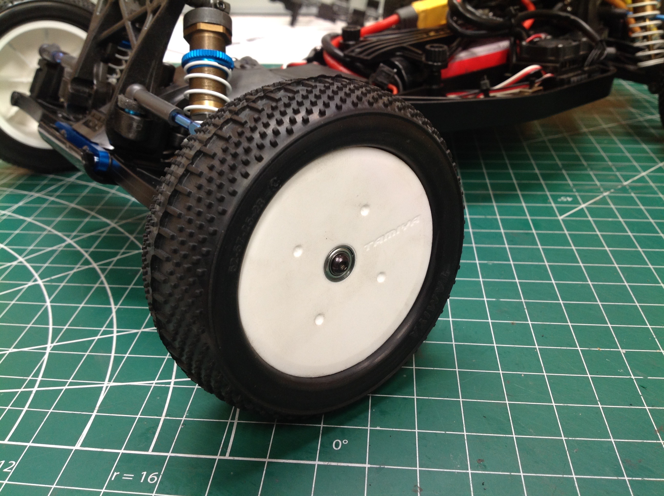
It is not unusual for the front wheels on 2WD cars to have the bearings
housed in the wheels, but usually they are installed with a 4mm
nut. In this case the hub actually has an internal thread so the
wheel is installed with a screw instead. The screw is not self
locking like a nut so thread lock is required. Both the front and
rear tires need to be glued to the wheels. I chose competition
compound dual block tires. Front are 25mm and rear are 35mm wide.
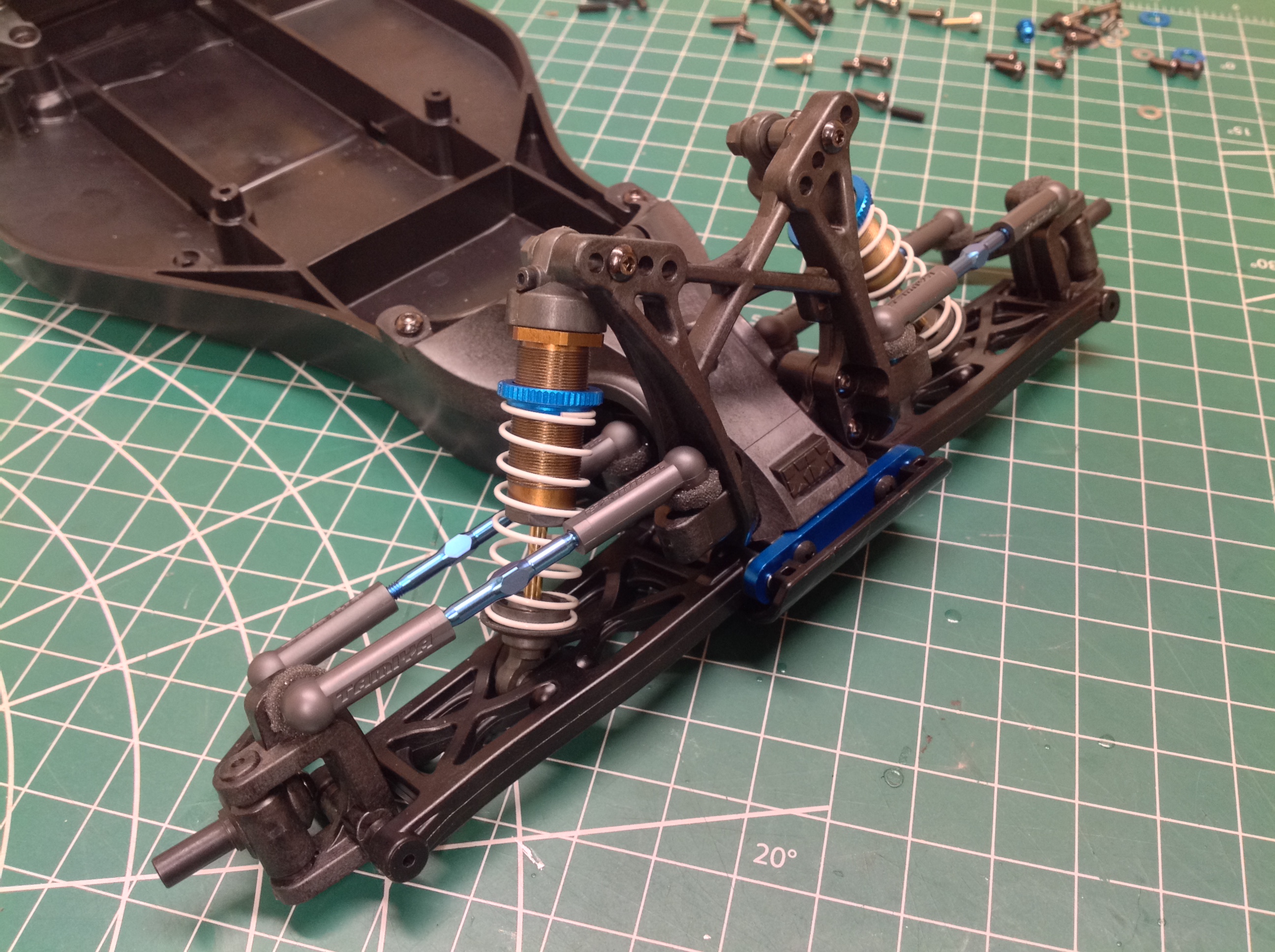
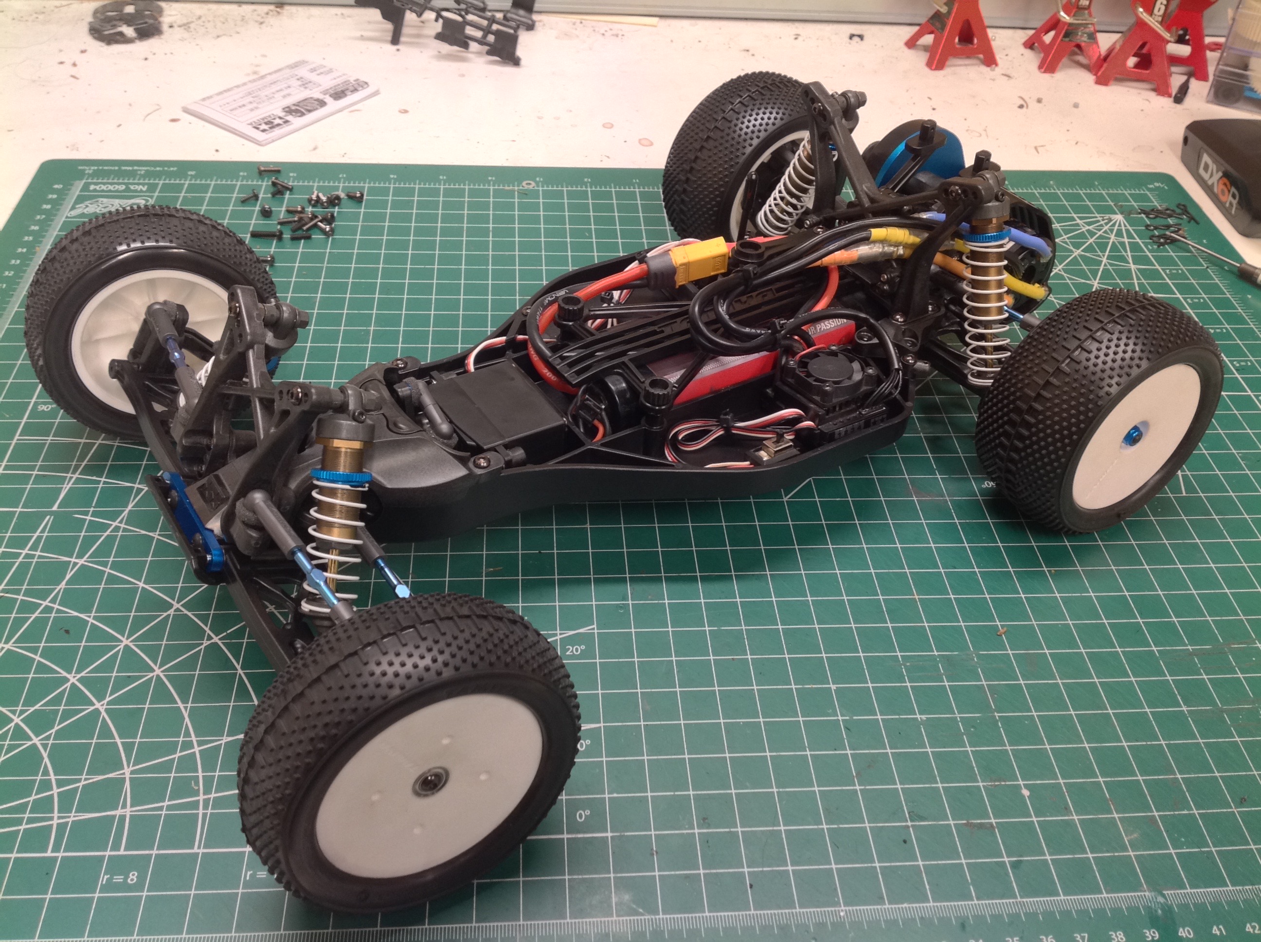
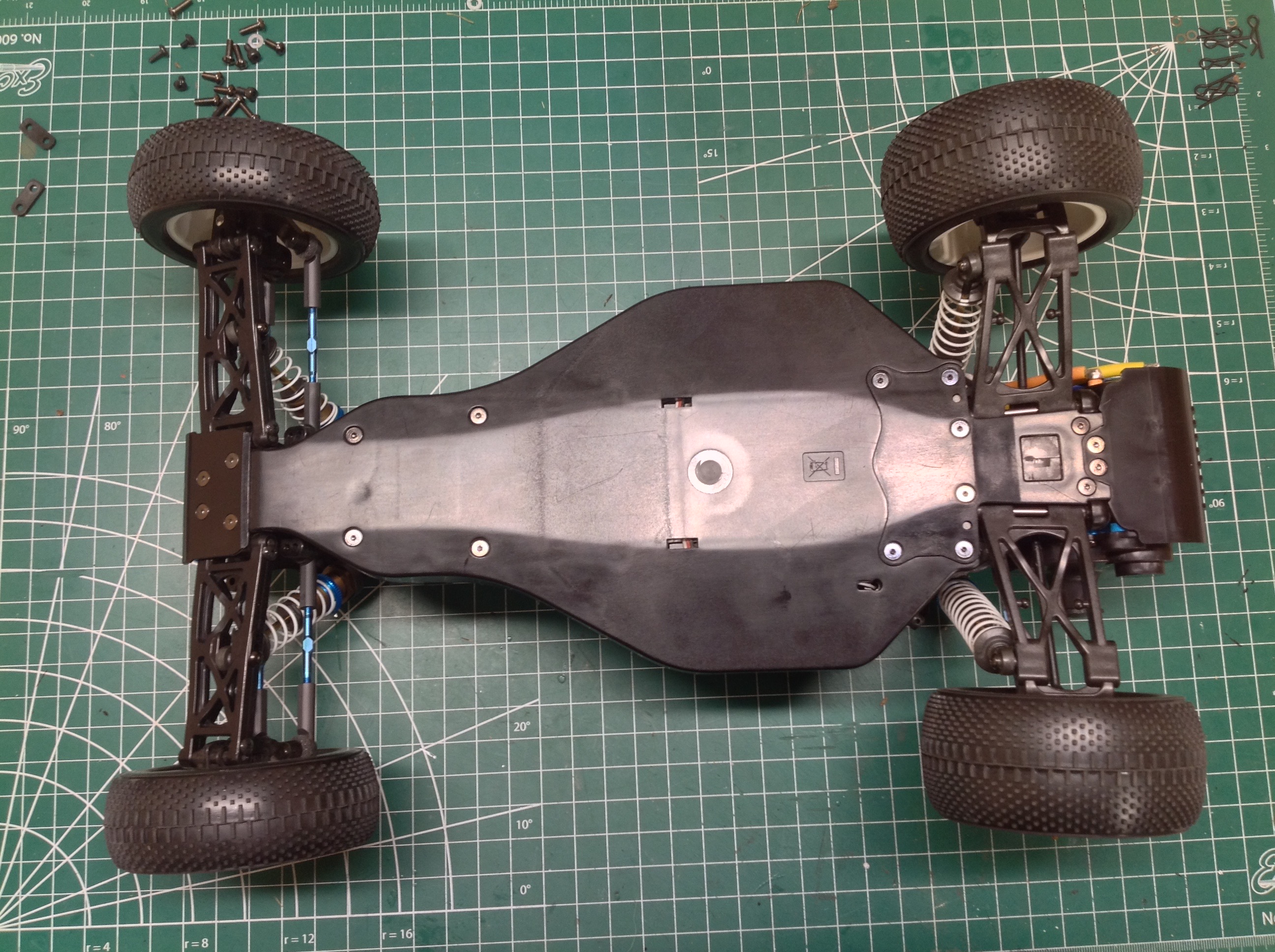
With the wheels installed, the rolling chassis is done. This is a
great looking and well balanced chassis. From the bottom you can
see the clean, smooth lines. You can also see the standard toe out
in front and toe in in the rear.
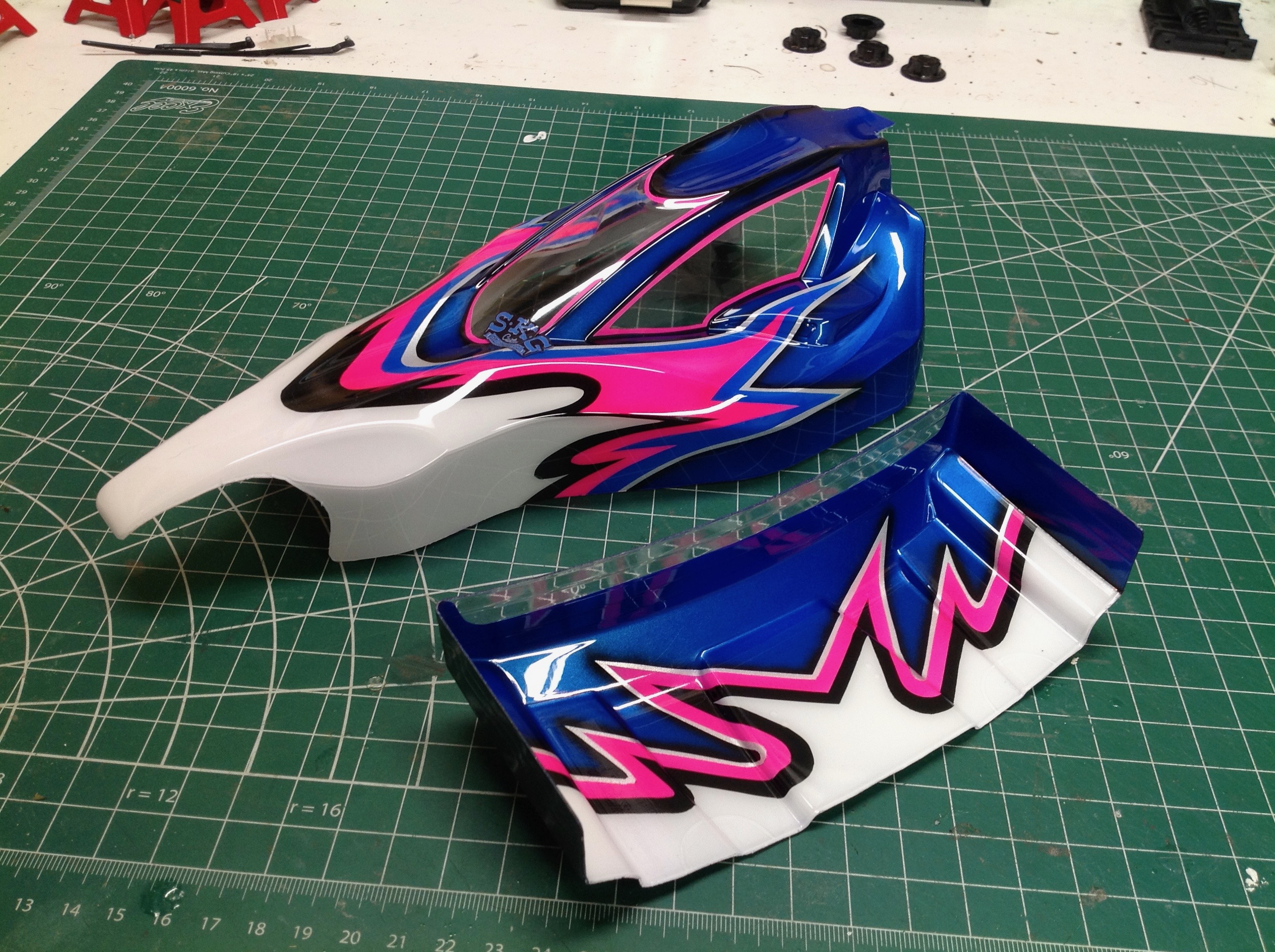
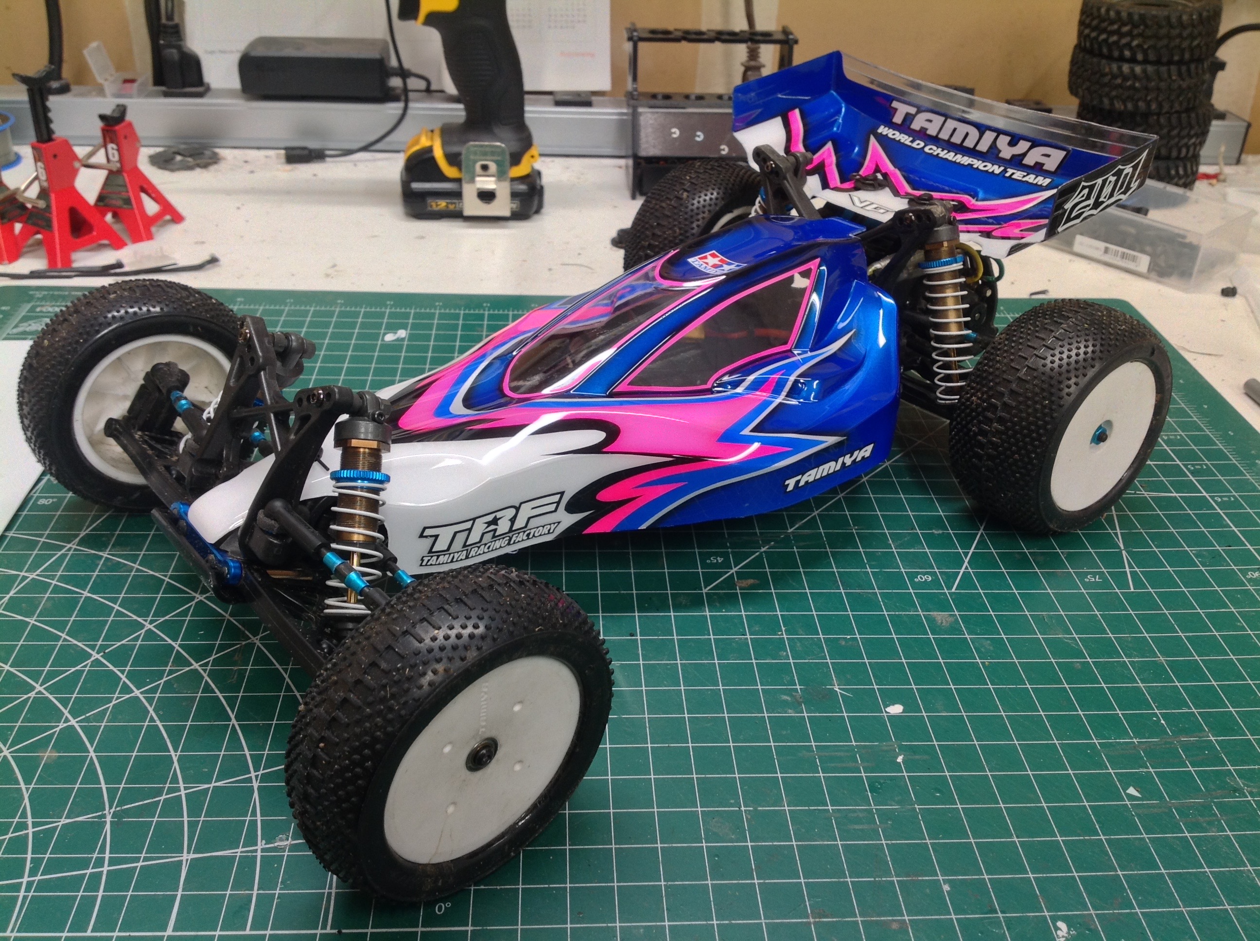
The body and wing came back from the painter better than I could have
hoped for. Hats off to SKG RC Painting for his stellar work
here. The kit does not come with the correct stickers to decorate
the car like the box art, but judicious application of the TRF stickers
looks pretty good. I kept them minimal so as not to hide too much
of the paint.
©2020 Eric Albrecht