Tamiya TRF201 Project
Page 3: Converting to XM
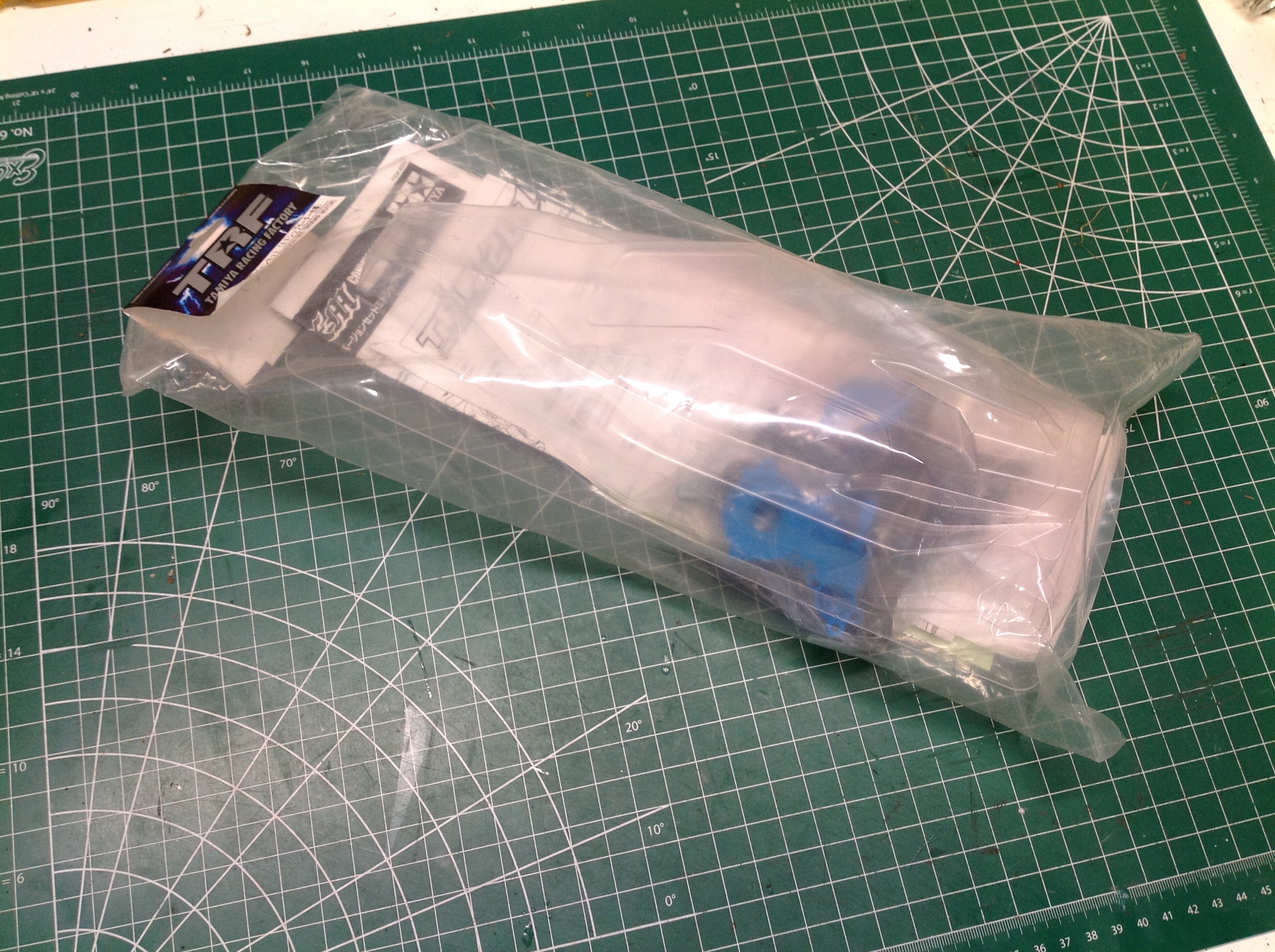
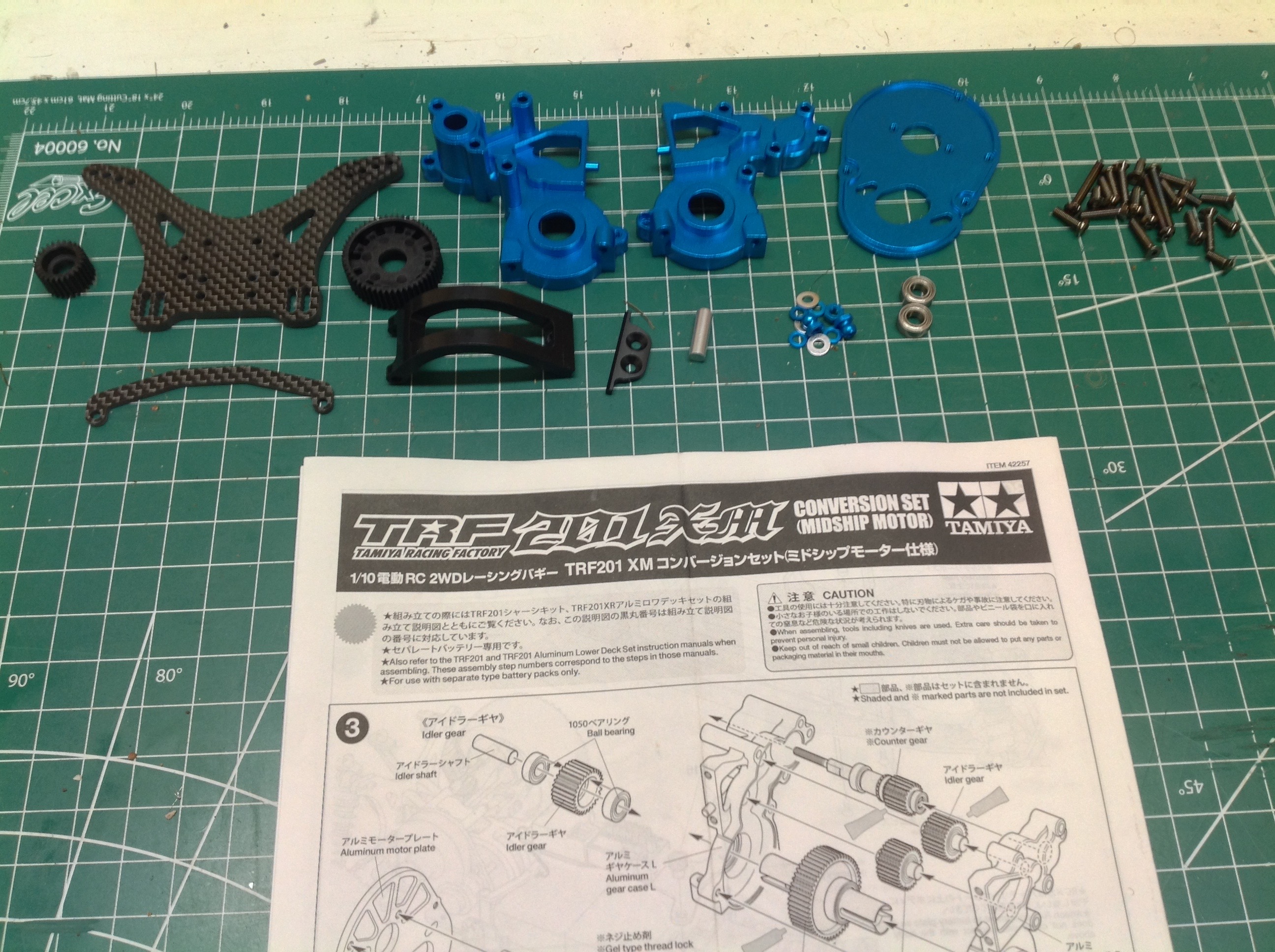
Here is the XM conversion kit which I purchased separately.
Although it doesn't come with very many parts, what it does come with is
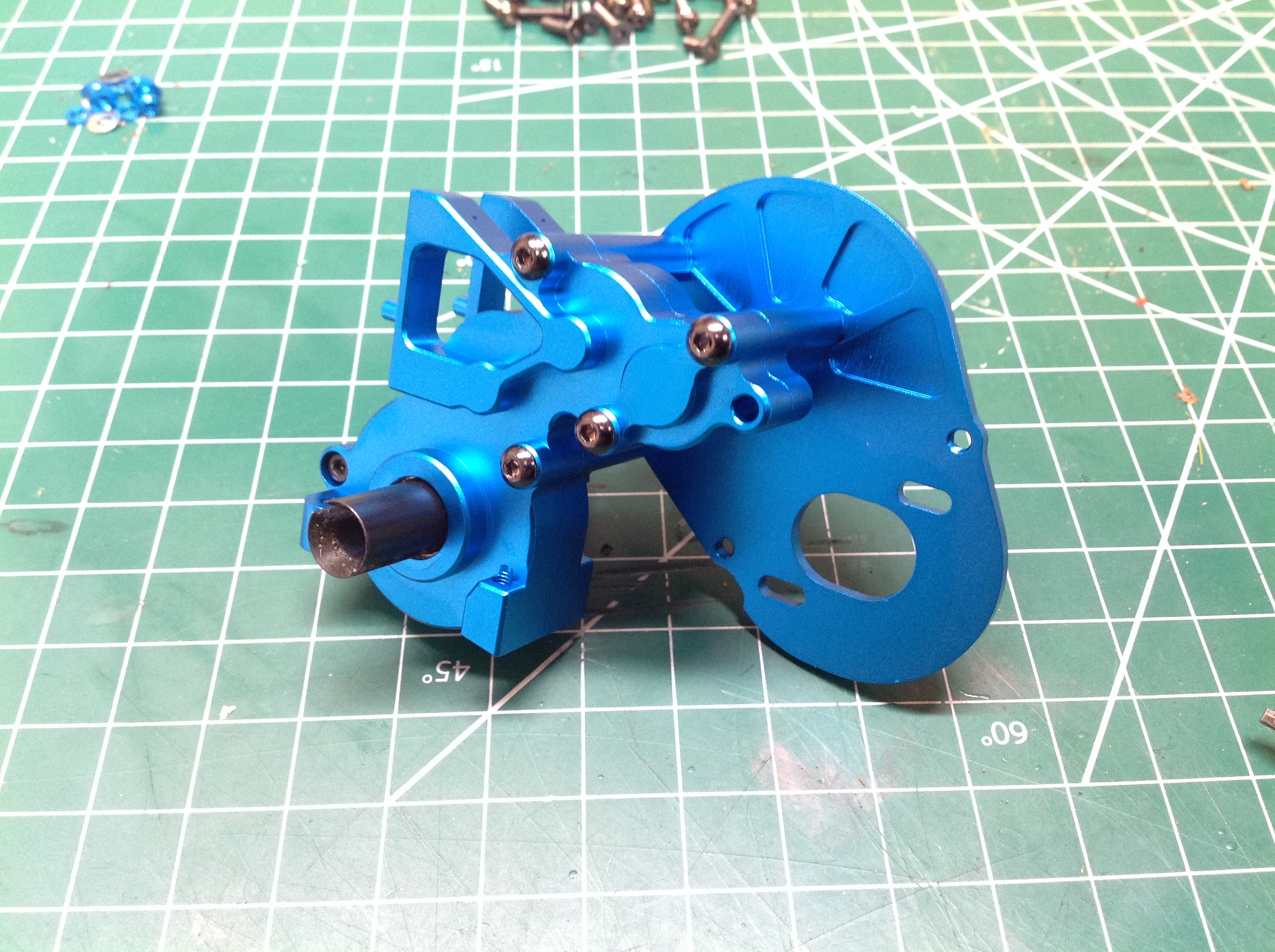
expensive. You can see machined aluminum transmission housings, a
heat sink motor mount, an aluminum motor guard, and a carbon fiber
shock tower and battery clip. There is also a new body included
which is a bit odd since the XM can only be made from the XR which uses
the same body. They can, however, be trimmed a bit differently at
the back to help hide the motor.
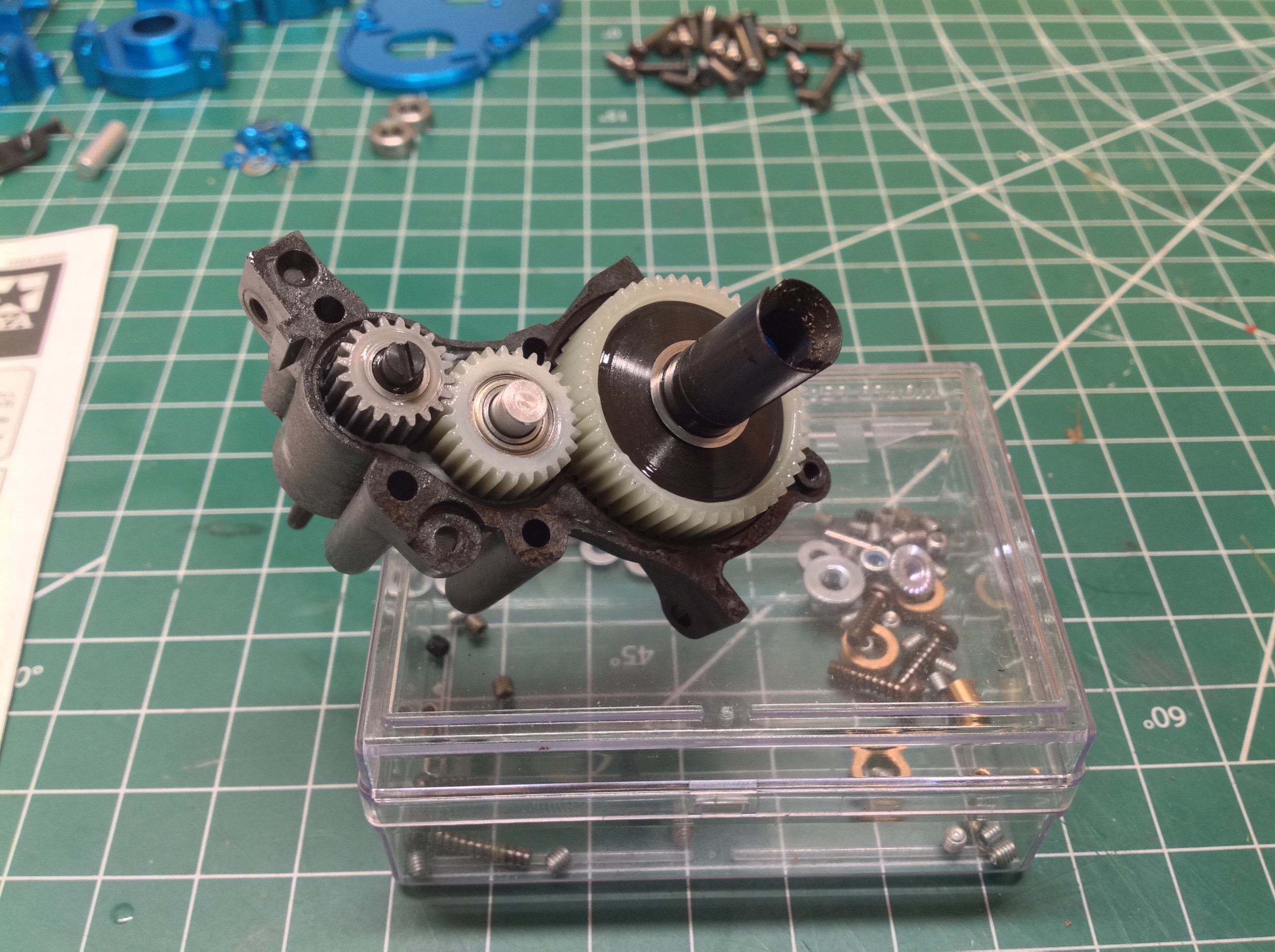
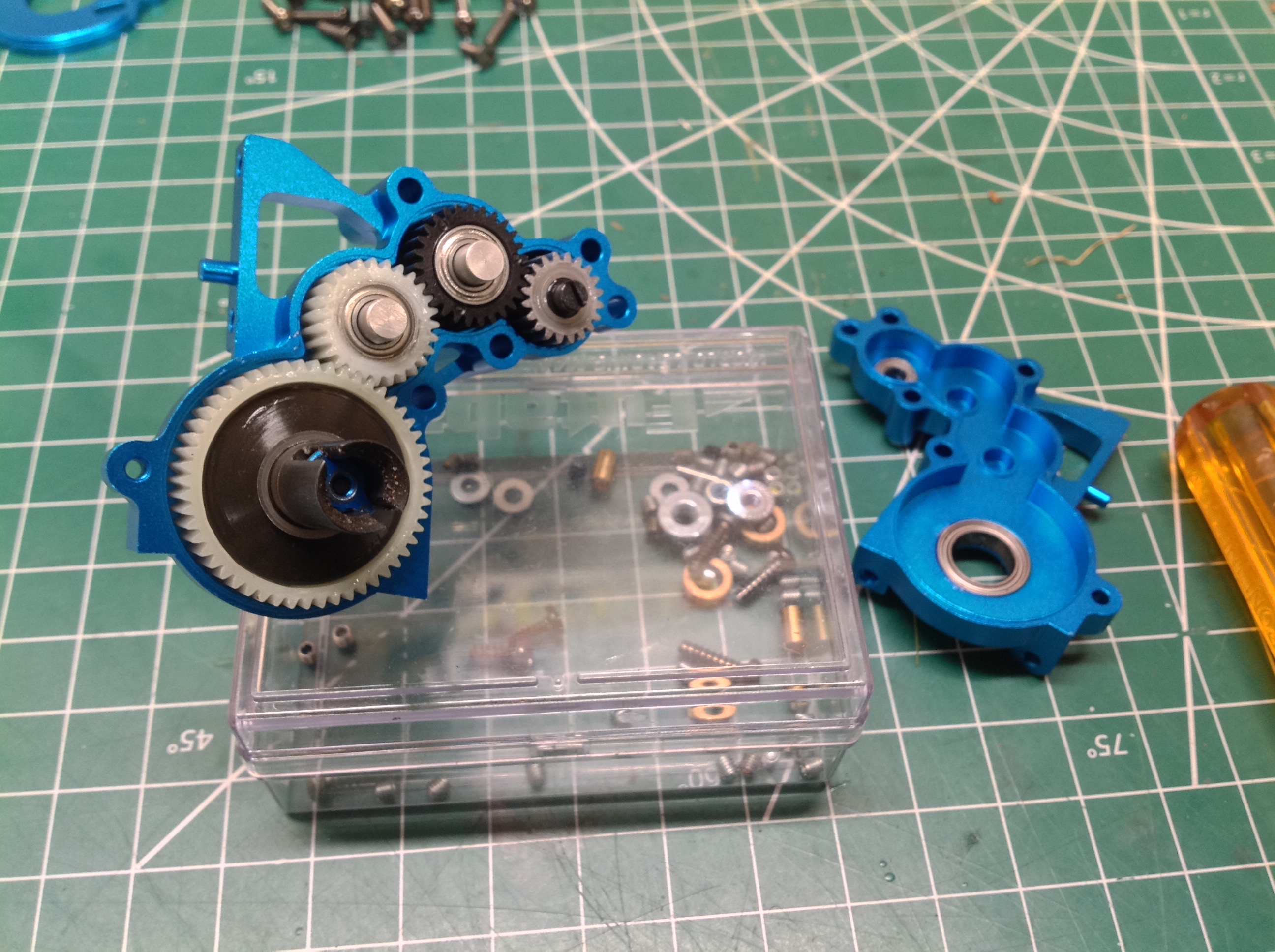
The original TRF201 transmission uses 3 gears. Because the XM
flips the transmission around to put it ahead of the rear axle, it also
needs to rotate in reverse. To accomplish this an additional idler
gear is added. The XM upgrade kit has this gear in black which is
supposedly an upgrade in some way, and also includes a new black ring
gear for the differential. I didn't want to rebuild the
differential so it stayed white. The left hand picture shows the
original transmission and the right hand picture shows the XM. It
wasn't strictly necessary for the XM to use aluminum instead of carbon
reinforced plastic, but I'm glad it does. It looks cool, and it
leaves me with an extra stock transmission.
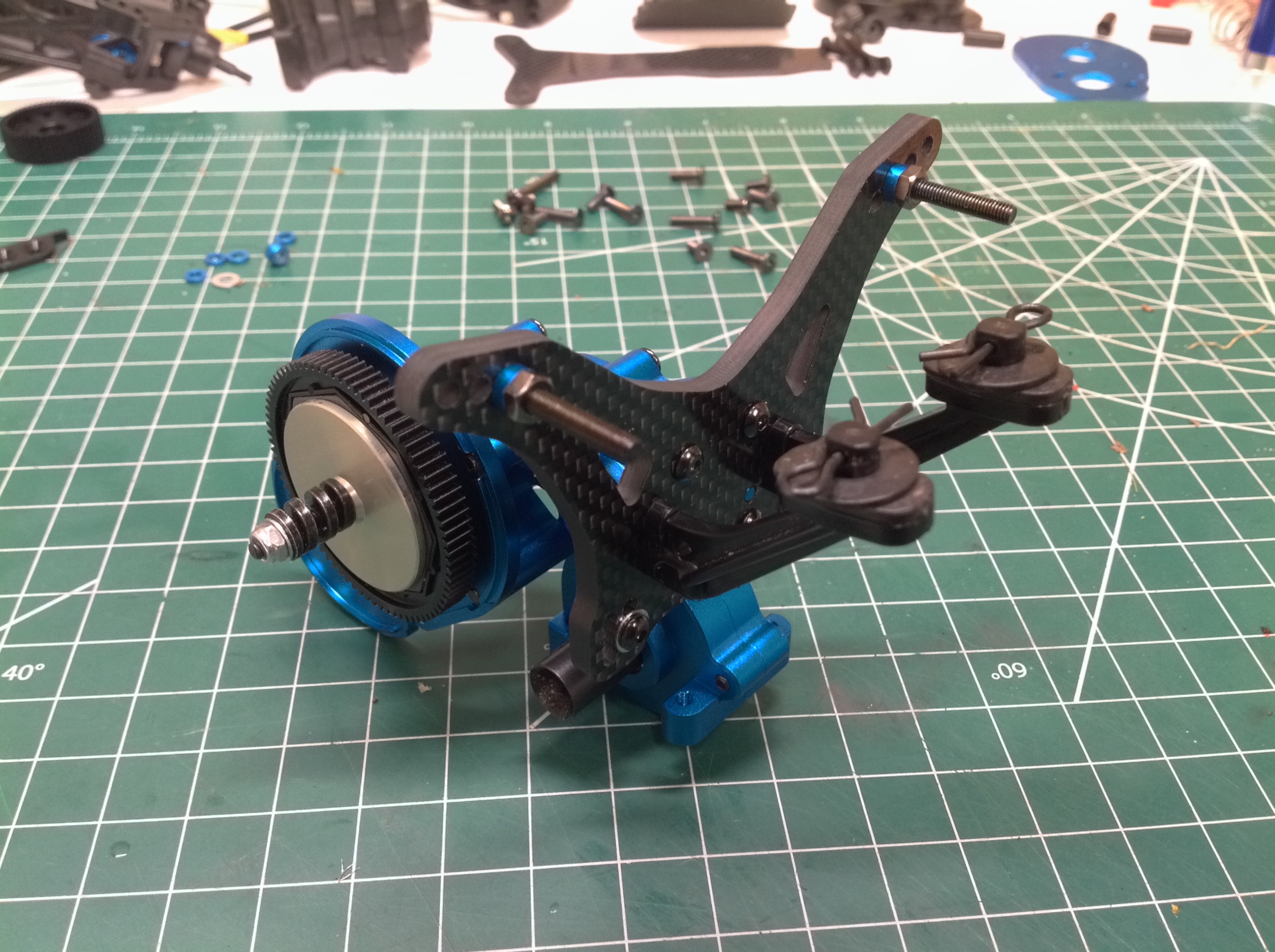
Here is the updated and completed transmission which also includes a new machined motor mount plate.
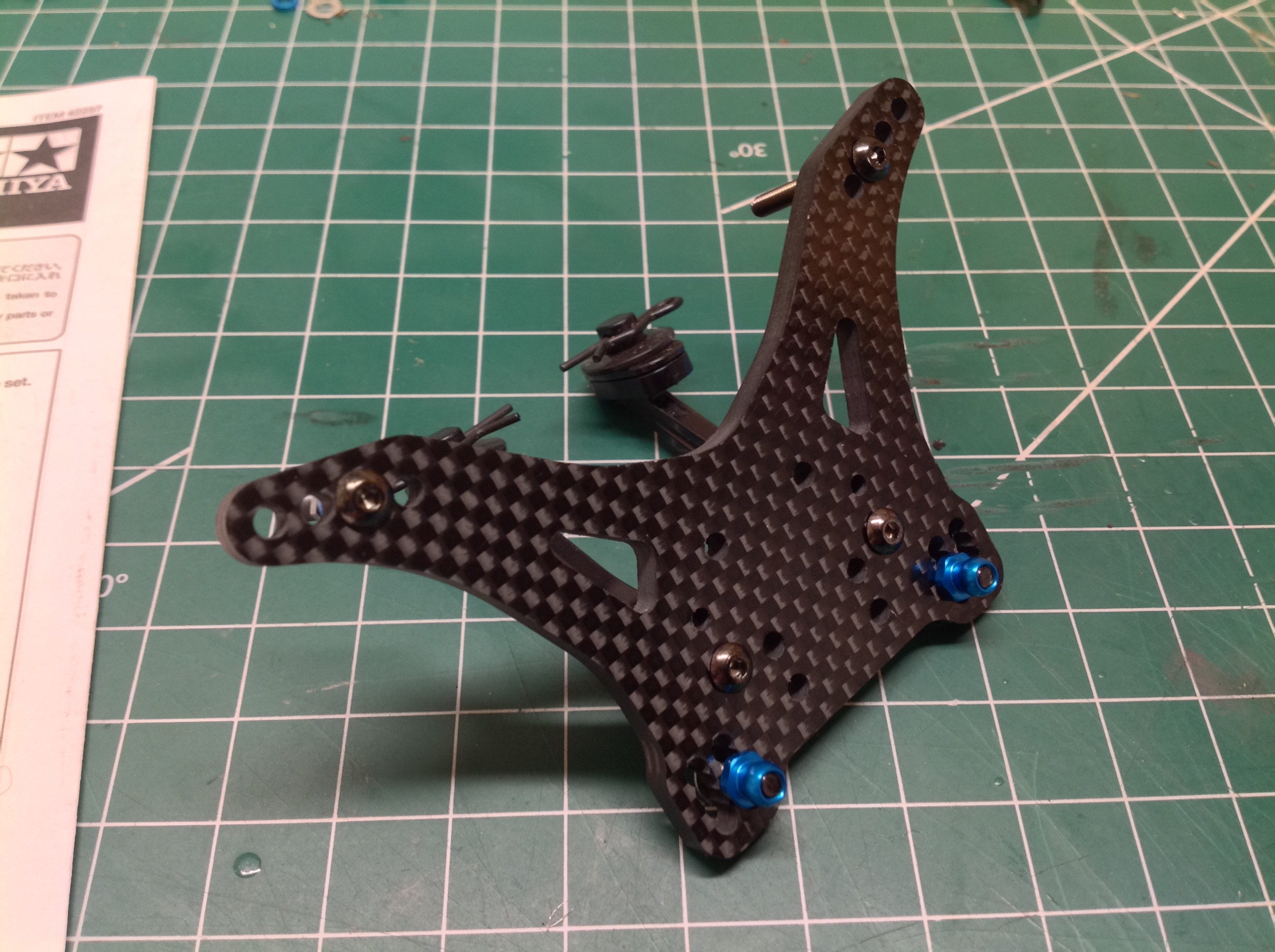
The original rear shock tower sat exactly where the new transmission
needs to go, so it had to be replaced. The new shock tower is an
incredibly thick (5mm) carbon fiber plate which bolts right to the
transmission housing. Part of the reason for the aluminum housing
was probably to make this connection nice and strong. The old
diagonal brace that spanned the gearbox and shock tower is gone.
The wing mounts also connect to the shock tower.
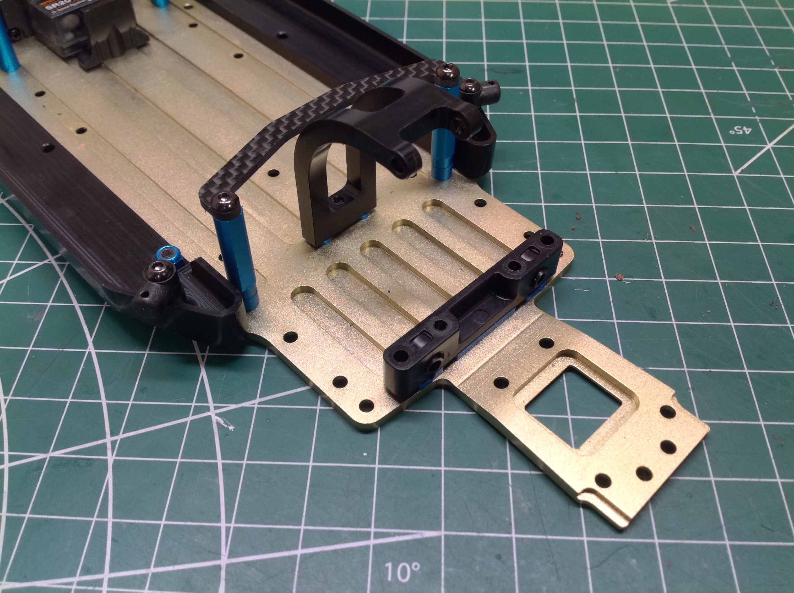
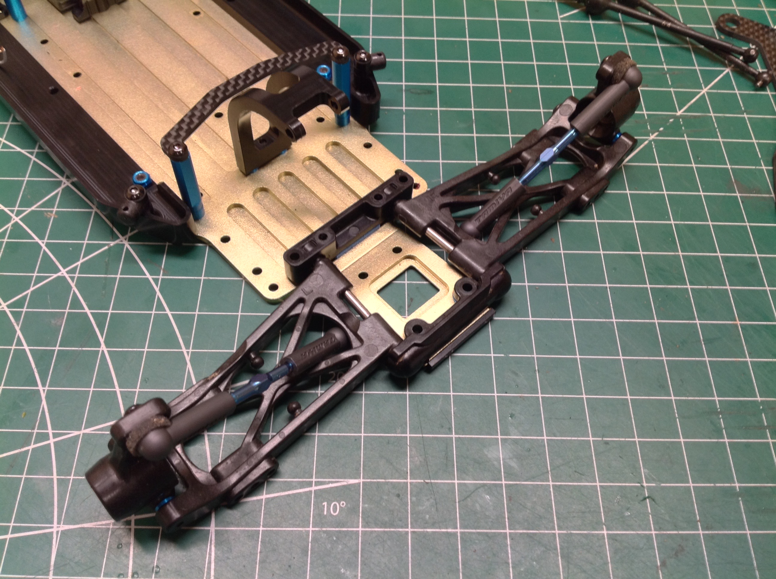
Now the old transmission and rear suspension can be removed to make room
for the new. Note that I've added a new curved aluminum motor
shroud. The carbon plate ahead of that holds down the back of the
battery. The suspension arms connect using the same parts as
before, but there is one subtle difference. If you read my build
of the original chassis you may recall that the
rear uprights were switched left to right (left labeled part installed
on right, right labeled part installed on left). Part of the XM
conversion is to switch them back the right way around. This
effectively moves the ball joint for the upper link from ahead of the
upright to behind it. This move will be needed for the new shock
tower position.
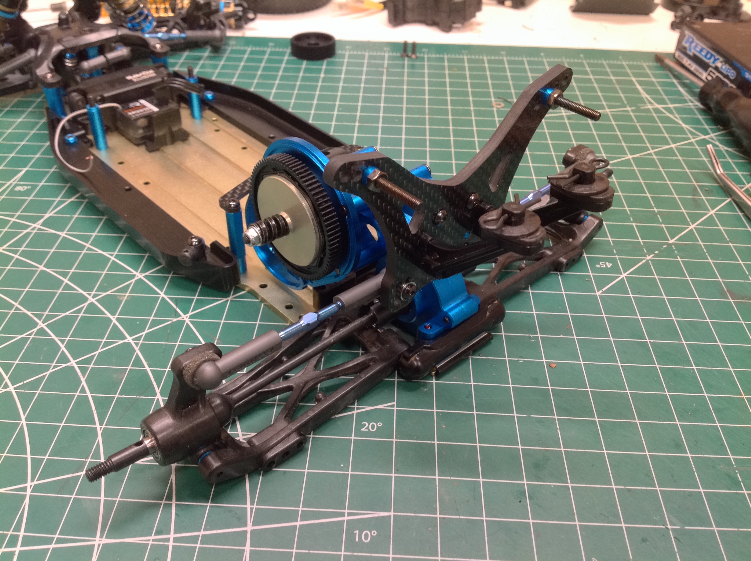
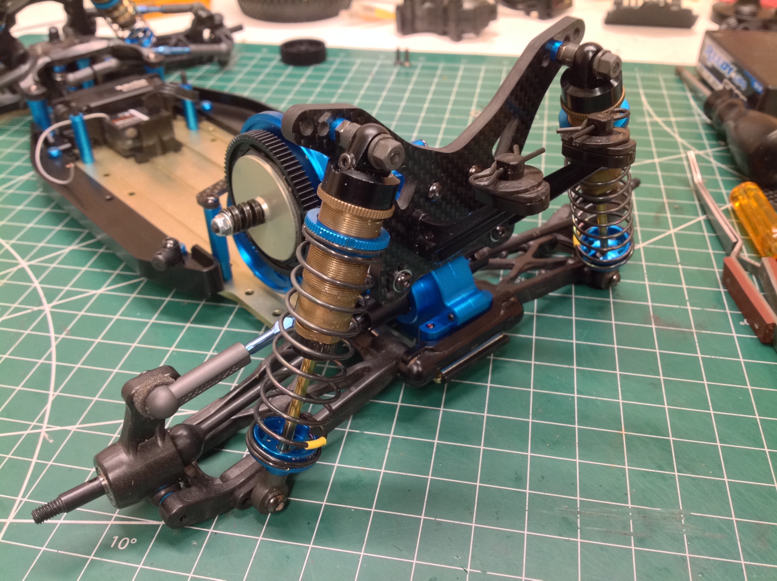
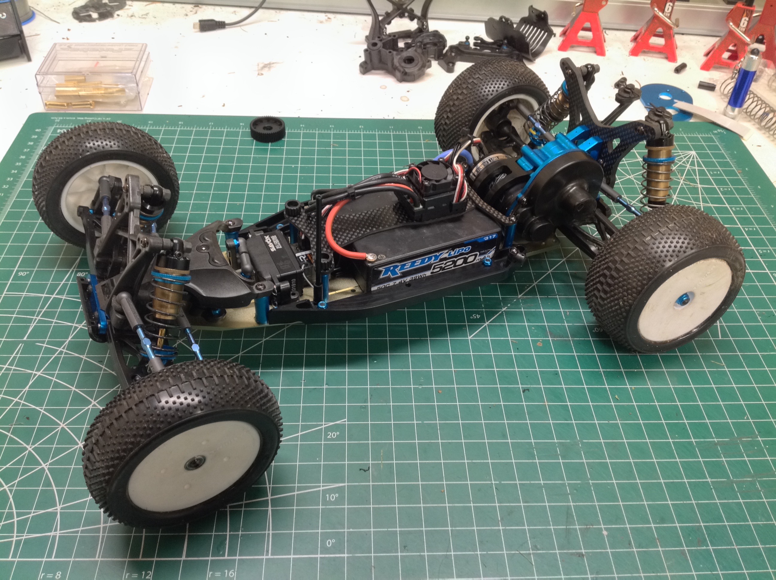
Now the new transmission assembly can be installed. Obviously the
output drive cups need to be in the same position as before to link up
with the axles, but the rest of the transmission has been moved well
forward. The big bore shocks now sit behind the rear arms instead
of ahead of them which moves them much closer to the wing mounts.
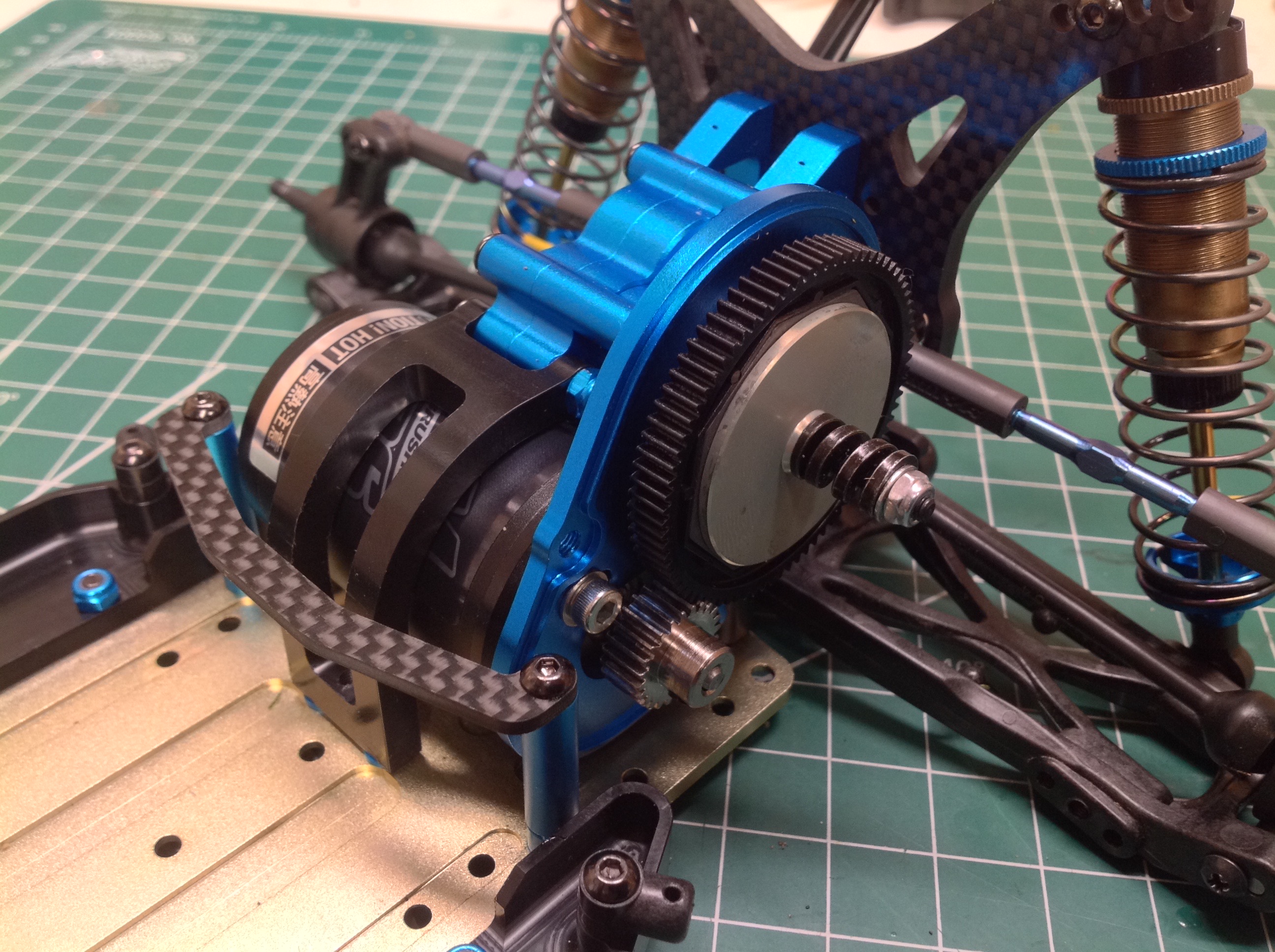
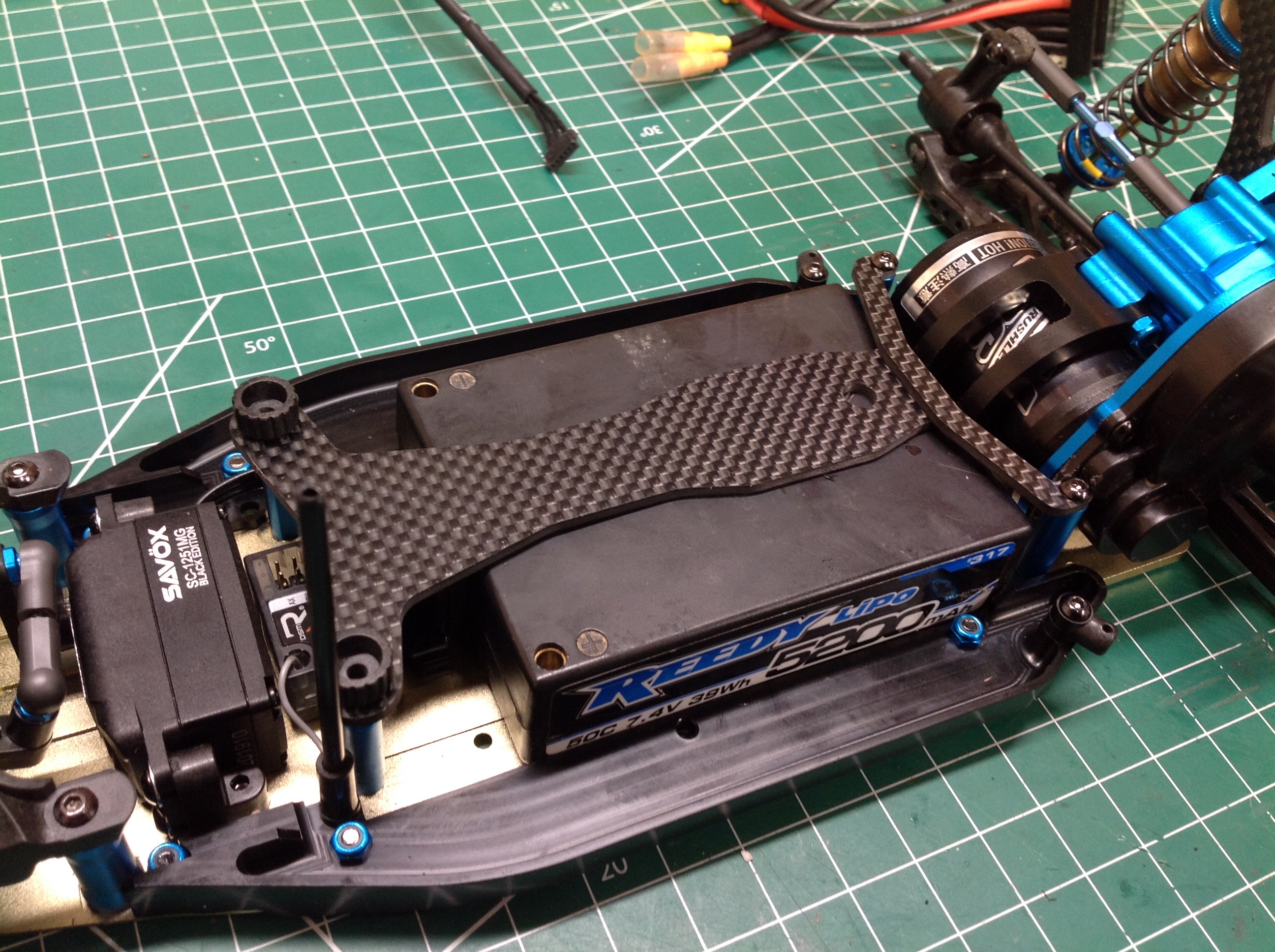
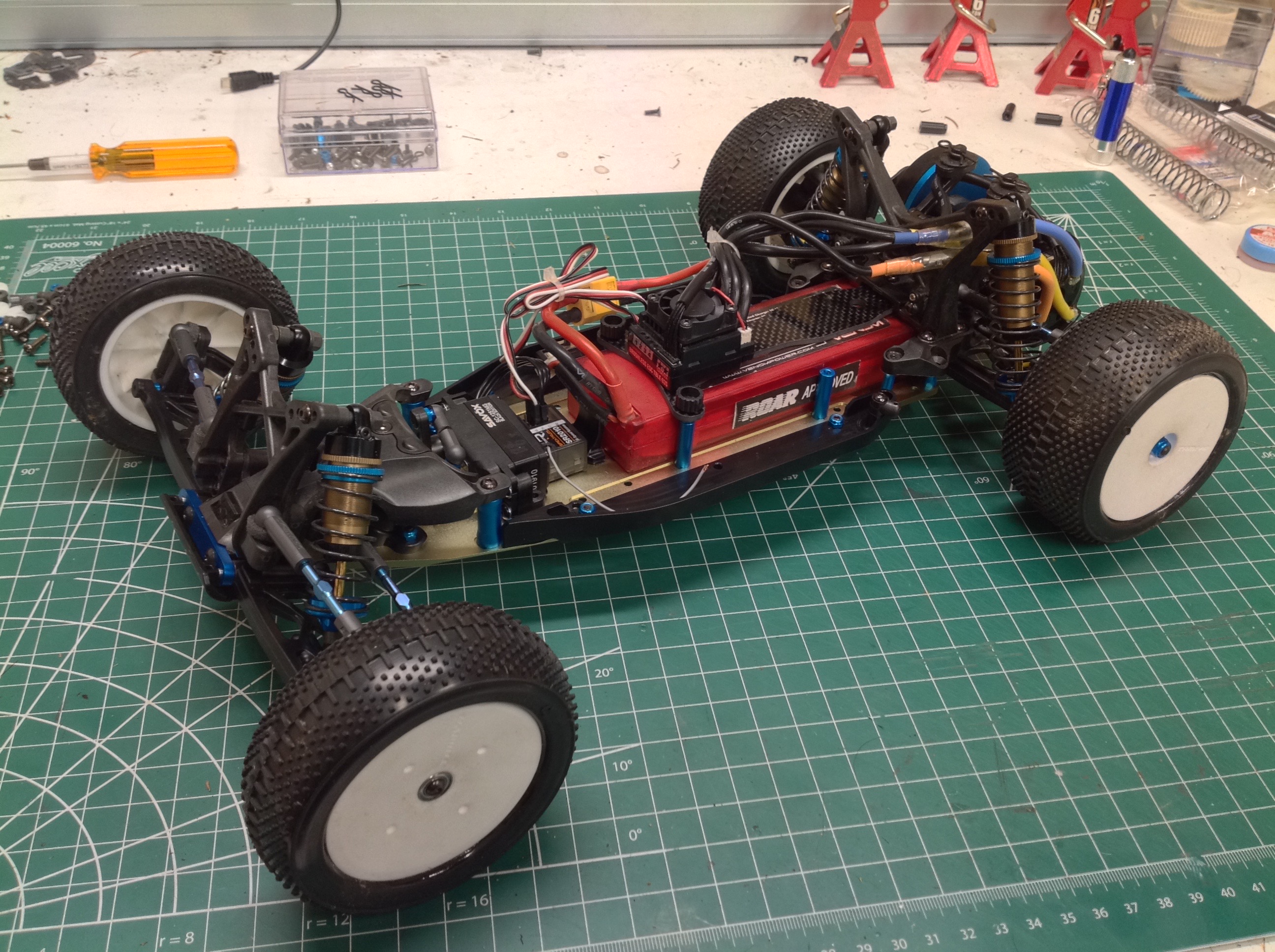
Here are some closer pictures of the new rear assembly with the motor
installed. With space on the chassis now taken by the motor, the
same long racing pack can no longer be used. The manual suggests
using saddle packs but I found that the square pack from the Short
Course Truck fits perfectly. This shape battery pack has become
quite rare so I may have to change to a different profile in the future.
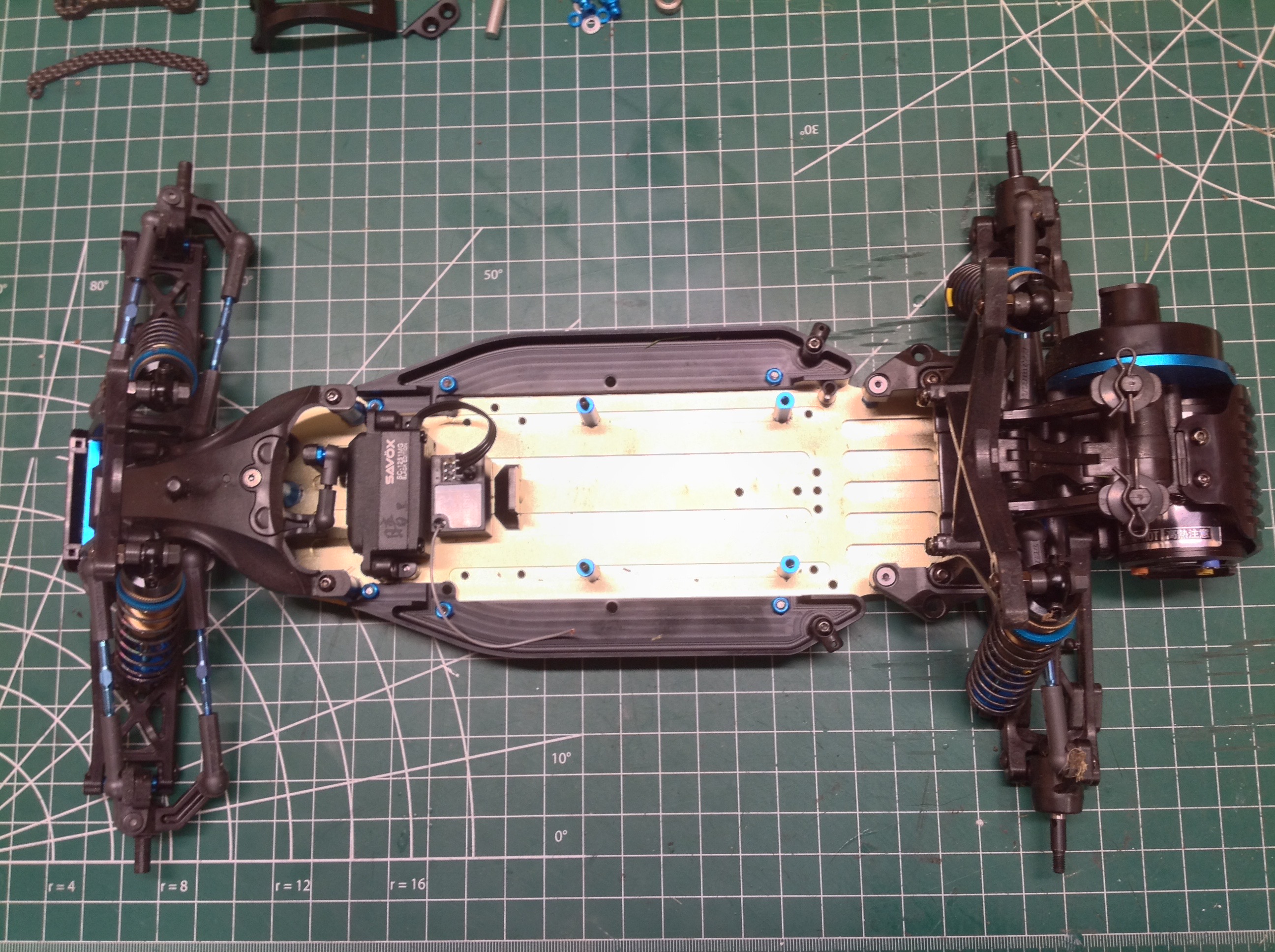
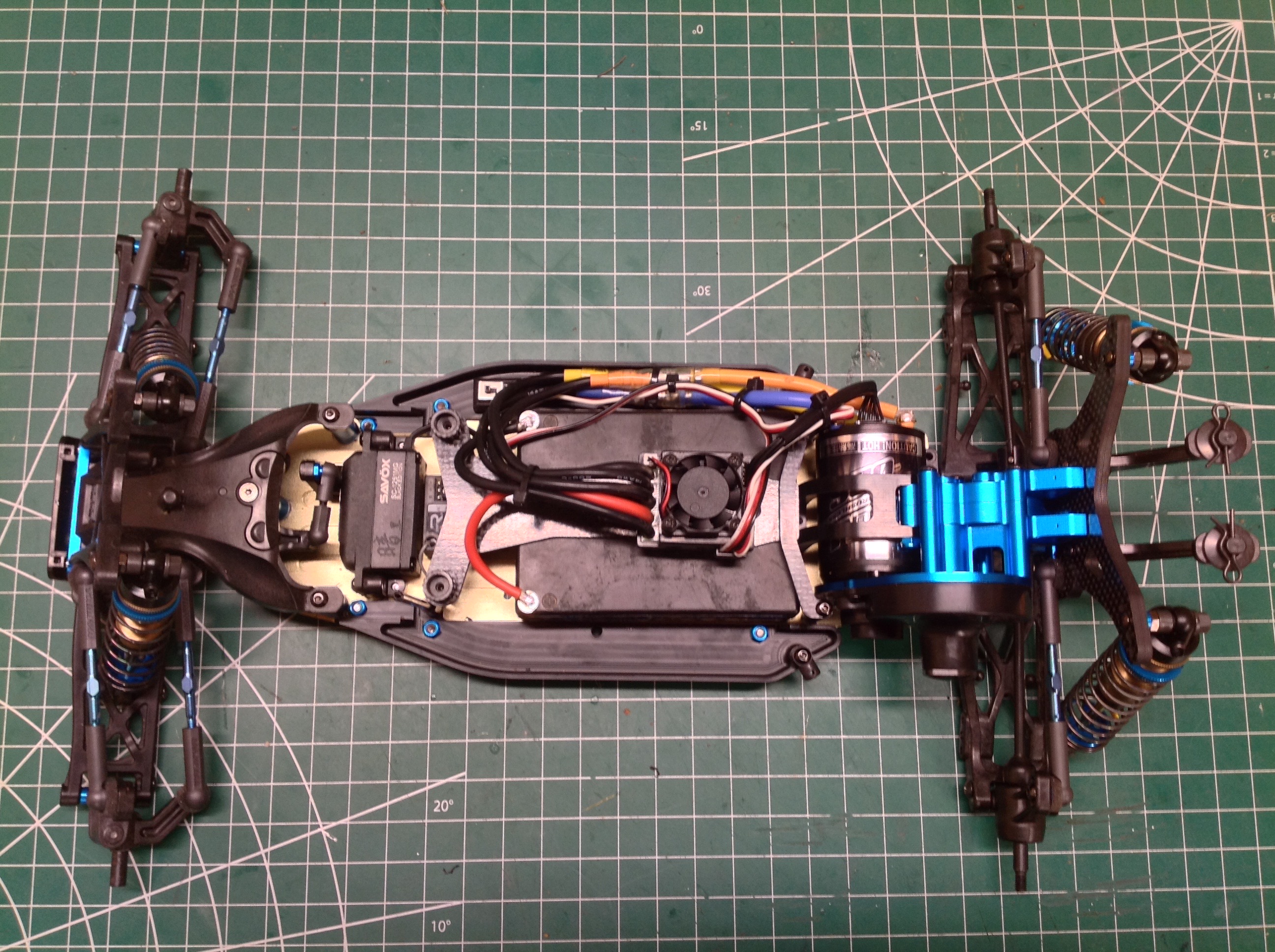
Here I compare the XR and XM chassis variants from above. The
front half is exactly the same before and after. In the rear you
can see how far back the shock tower has moved. You can also see
that the rear upper link and shocks have moved behind the rear
suspension. The motor, obviously, has been moved forward.
And the new version has a lot more blue.
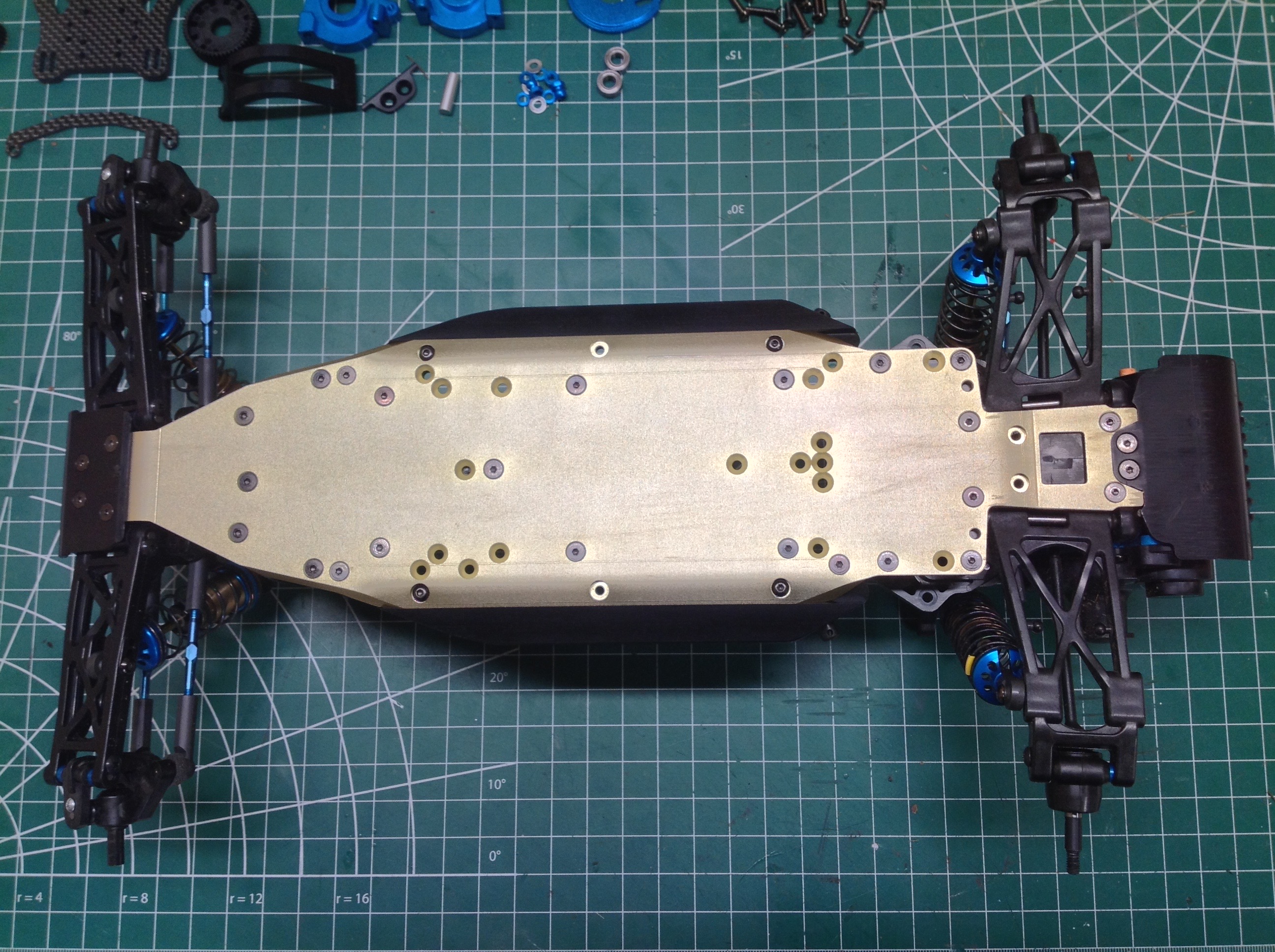
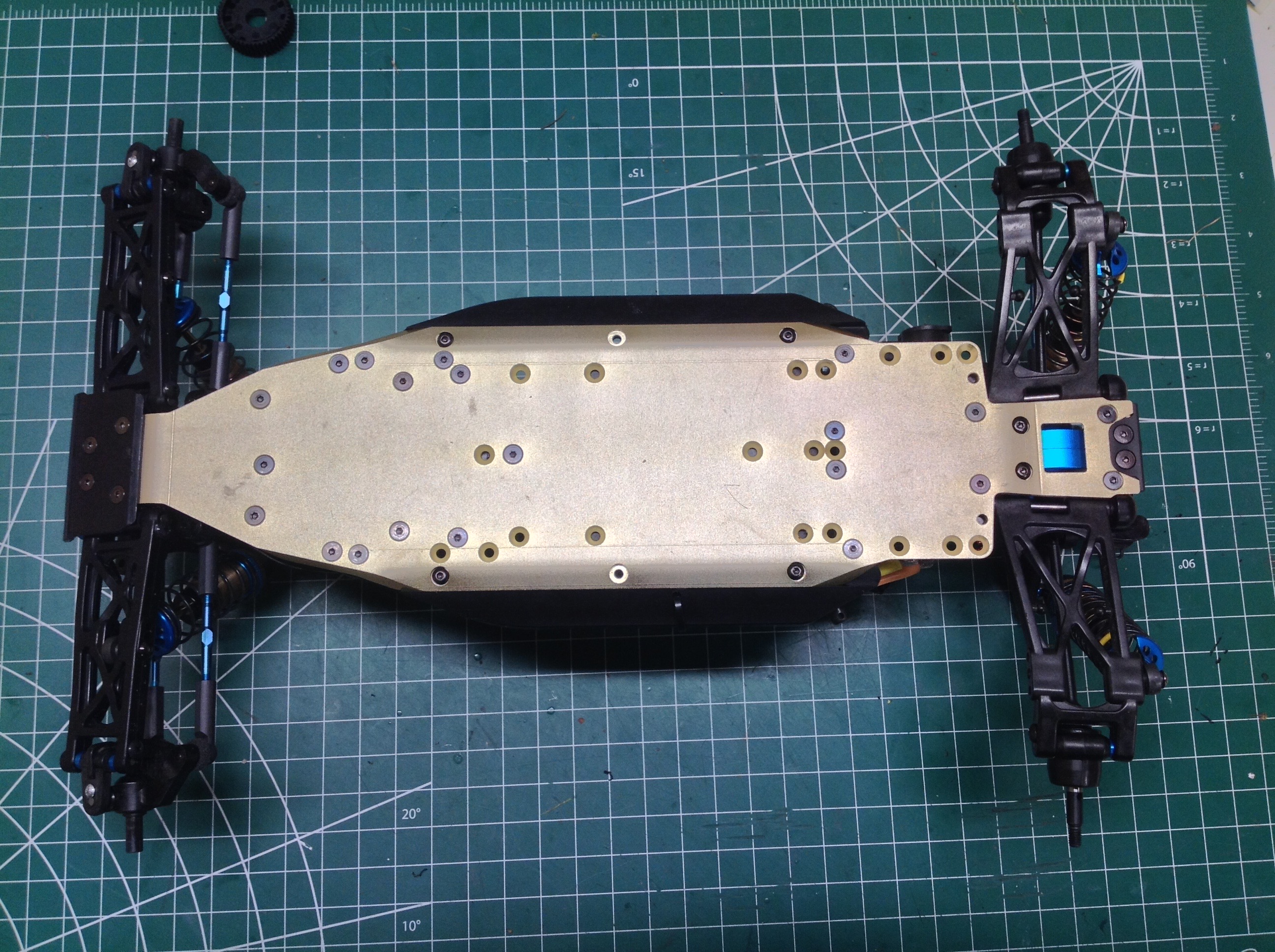
Here I compare the XR and XM chassis variants from below.
The wheelbase is exactly the same but you can see the blue transmission
housing through the slot in the rear, and the position of many of the
countersunk screws has changed. The XM version was obviously
already planned at the time the XR was released because the chassis
plate had all the hole options drilled for it.
Here I compare the XR and XM chassis variants from a 3/4 view. The
XM has the illusion of being longer because the shock tower has moved
back.
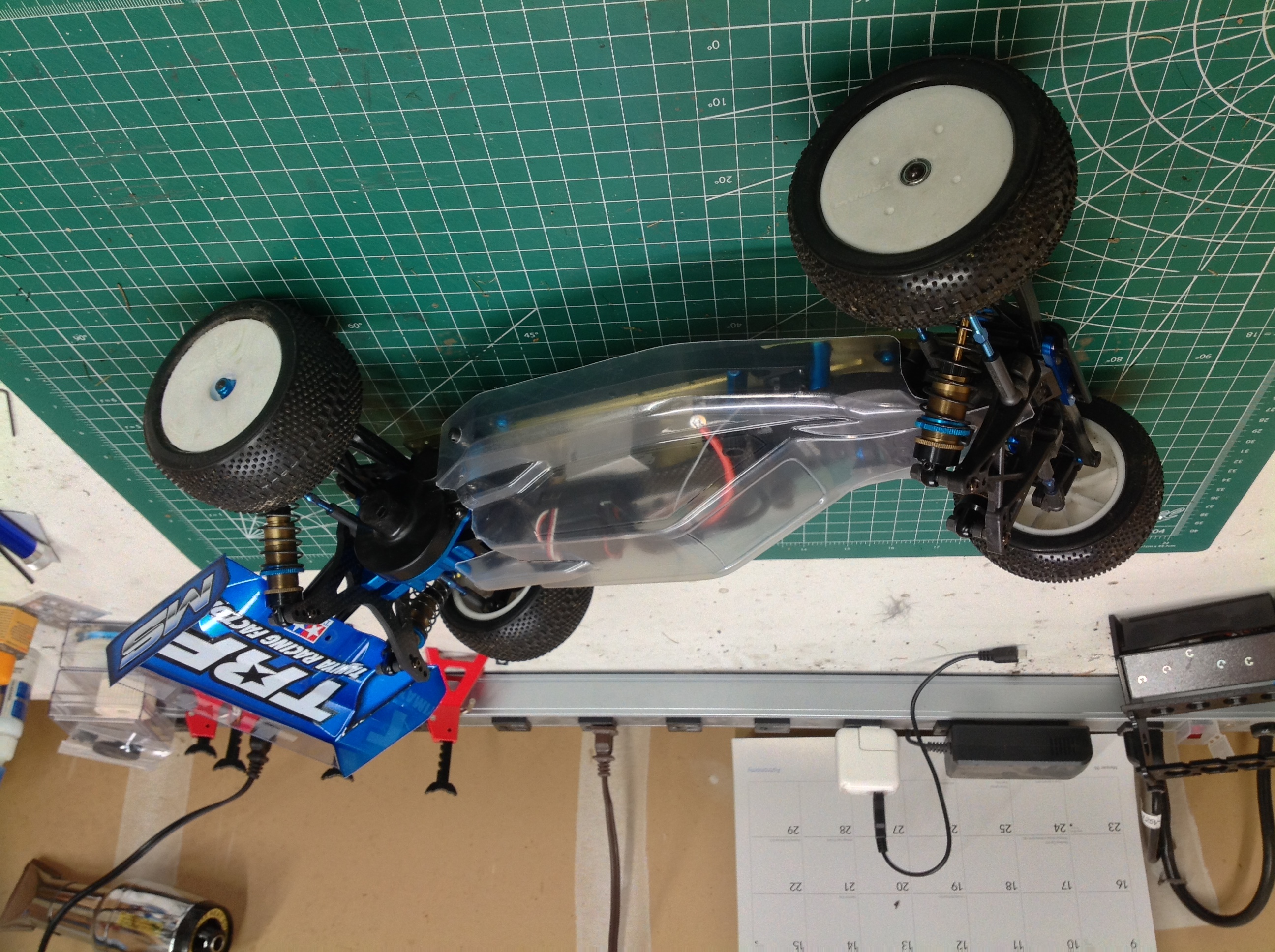
I ended up with two bodies because one came with the 42167XR kit and one
came with the XM upgrade kit. I sent one off to the painter and
used the other for a test fit as shown. It leaves very little room
for the ESC but it looks like everything will work. One hangup
(literally) is that the thumbscrews used to hold down the battery touch
the sides of the window which may cause a problem scratching the
paint. The wing you
see in this photo is not correct, I borrowed it from a DT-02 MS just to
see how it looks.
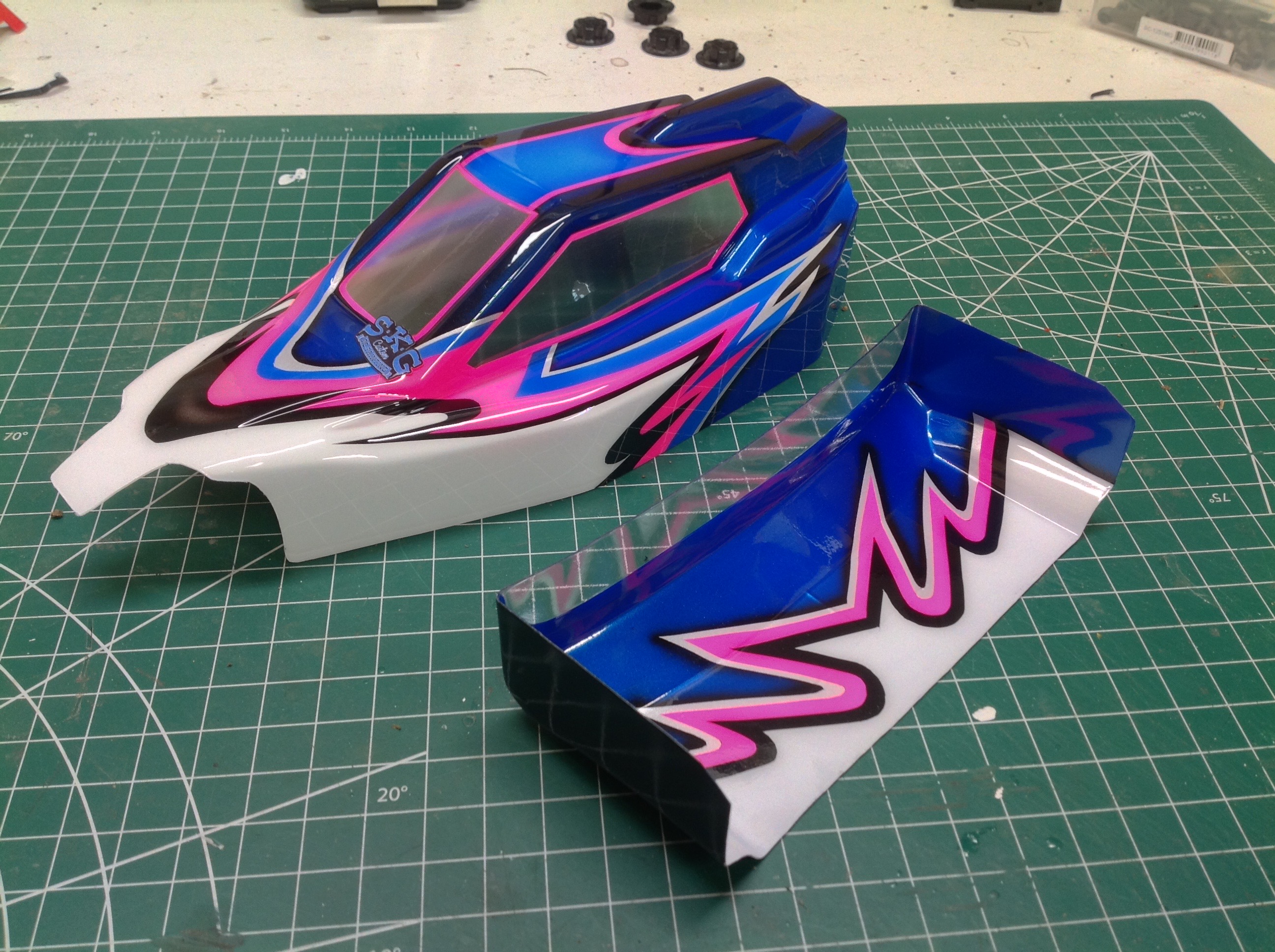
Here are the body and wing as they came from the painter. I failed
to heed my own advice and scratched the paint at the front corner of
the window when test fitting the body. I was most chagrined.
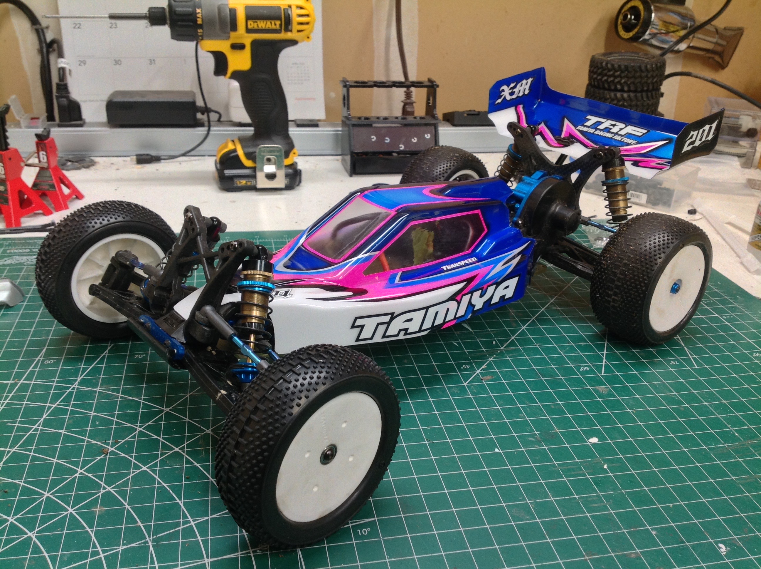
I could black out the windows and put protective tape over them, but
the battery screws would still interfere and prevent the body from
fitting properly. I will probably just remove the thumbscrews and
use standard nuts. I decorated the body with a handful of TRF
stickers as shown.
©2020 Eric Albrecht