Tamiya TRF 420X Project
Page 2: Assembling the Chassis
While writing about this build, I am going to concentrate on the
differences between this and the last chassis in the TRF line I built
(the TRF 419).
There are a lot of new parts in this kit. While the chassis
plate and aluminum parts almost always change between model versions,
most of the plastic parts stay the same and some have been used for
decades. Let's explore some of the new parts and see where they
came from.
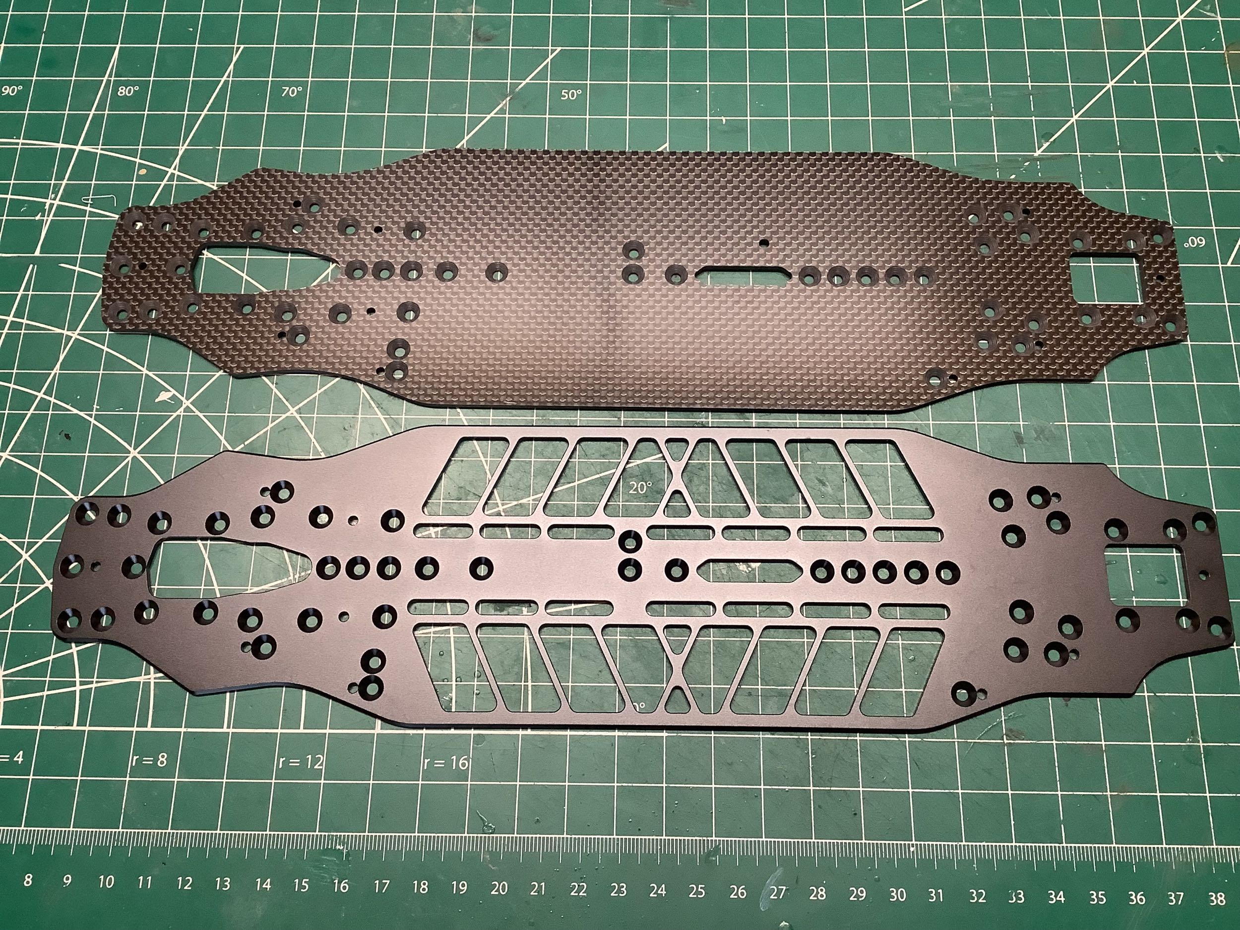
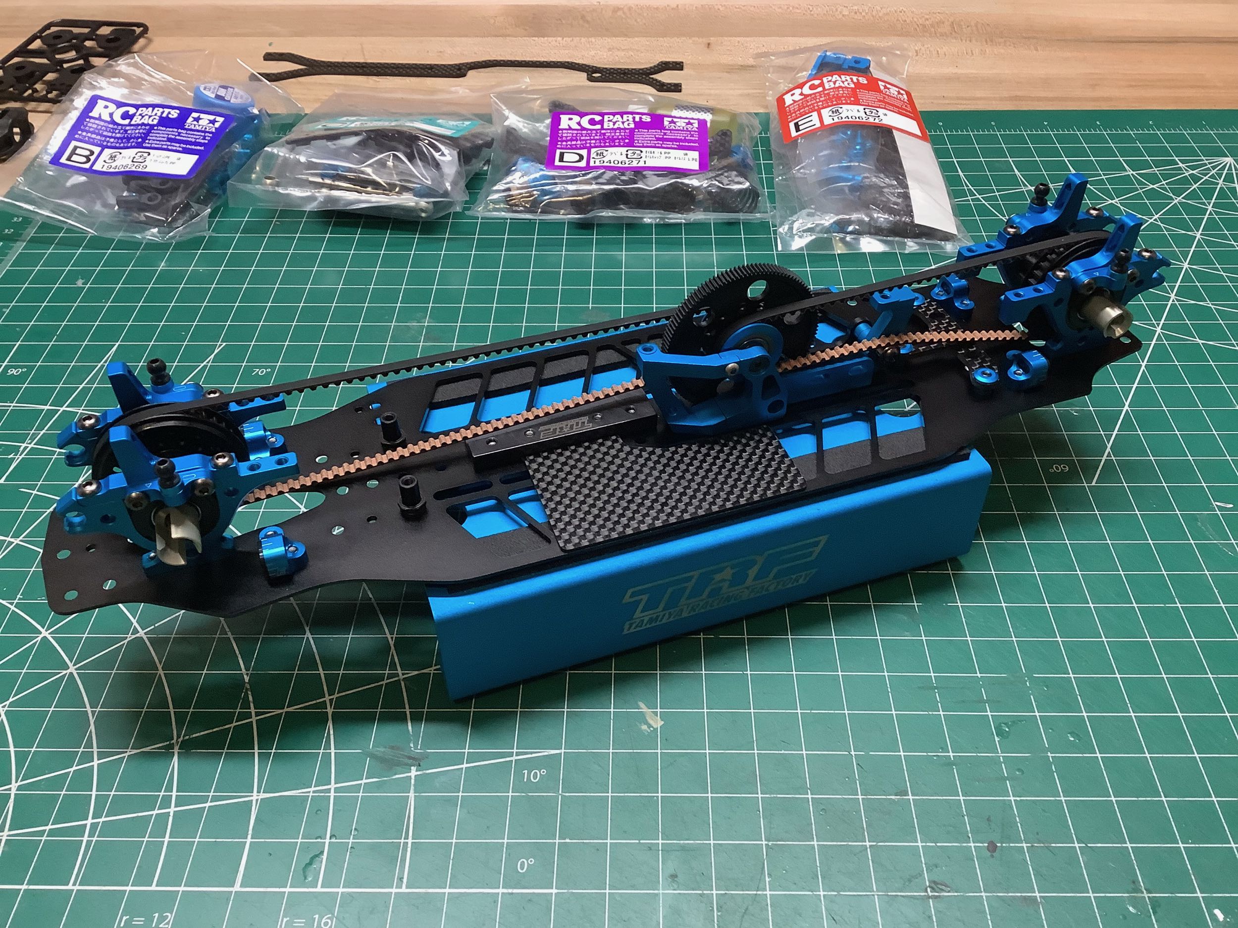
By far the most obvious thing you'll notice when you open the box is
that there are two lower chassis decks included. The 2.25mm thick carbon
plate is what you would expect to find in a TRF kit, but the 2mm thick
optional aluminum chassis is a nice bonus. Previously there was an
optional aluminum chassis (42350)
available for the TRF 420, but this is not the same part. It is
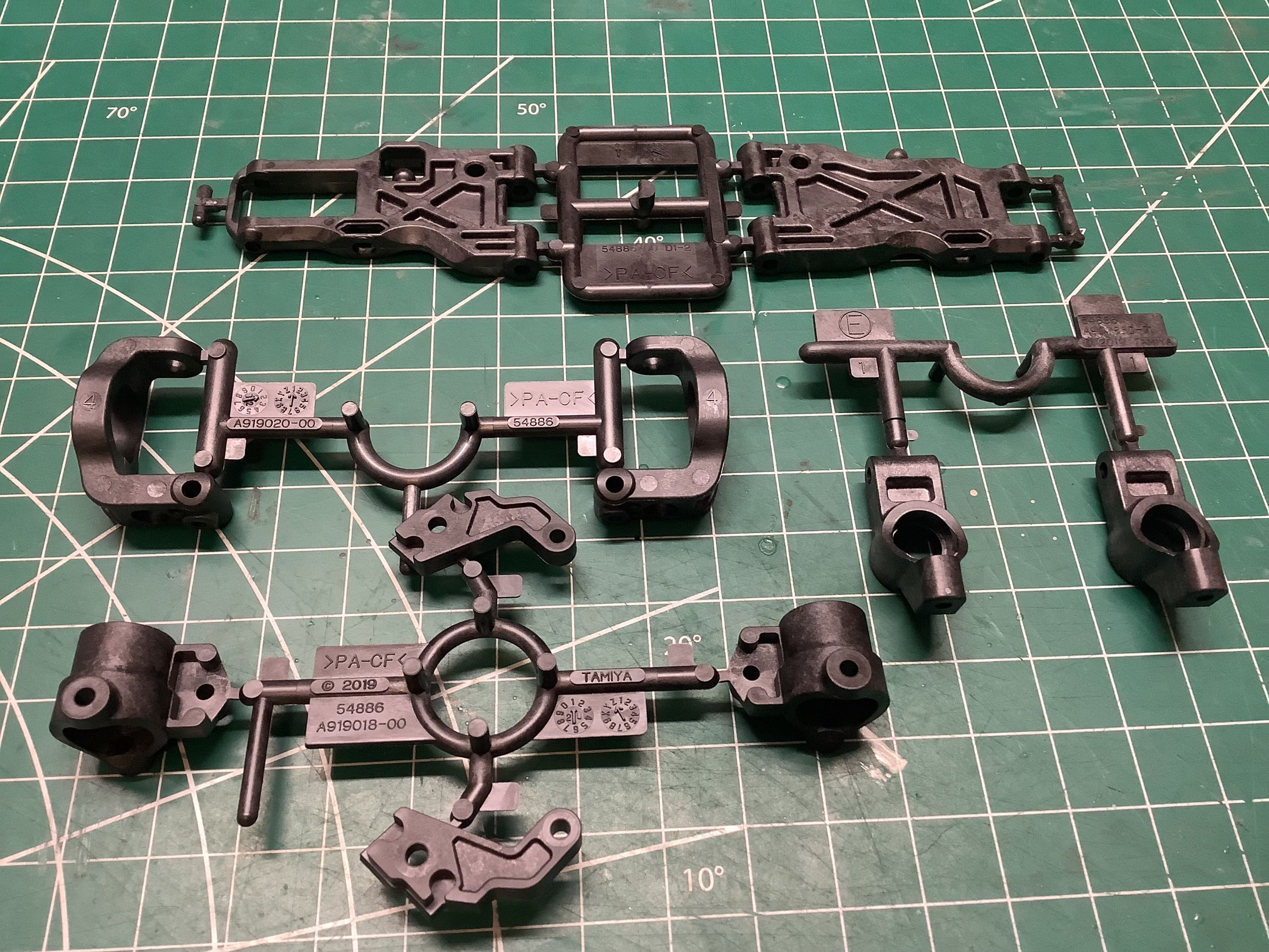
actually unique to the TRF 420X. On the right you can see the
suspension components (C-parts [knuckles], D-parts [lower arms], E-parts
[uprights], and F-parts [C-hubs]) which are all carbon filled Nylon and
stamped with 54886
(2019) which marks them as coming from the TRF 419 Suspension Upgrade
Set. Even though these parts were sold as an upgrade for the TRF
419, they came out 2 years after the last version (TRF 419XR) but the
same year as the TRF 420. Since both versions of the TRF 420 came
with these parts out of the box, they were probably designed for the 420
but made available for the TRF 419 for backwards compatibility.
Note that because they use 3mm hinge pins instead of the previous 2.6mm,
they must be used as a matched set and cannot be mixed with older
parts.
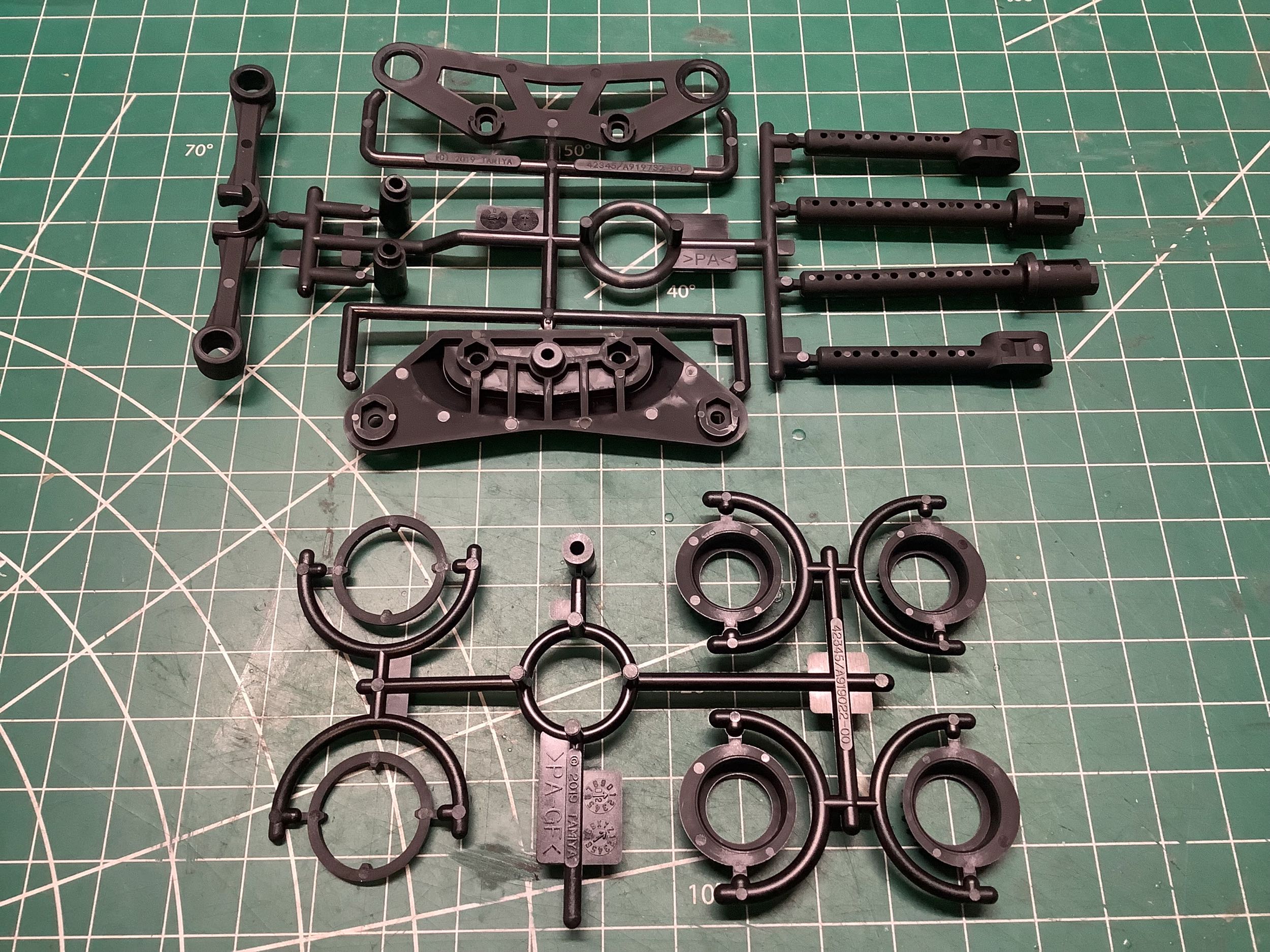
On the left you can see the B-parts (plain) and K-parts (glass filled)
which are also also Nylon and marked with 42345 (2019) which means they
were new for the original TRF 420. The body posts had been the
same all the way back to the TRF 414, so changing them now is really a
milestone. The K-parts include the differential bearing retainers
which have been updated and also some shields for the center
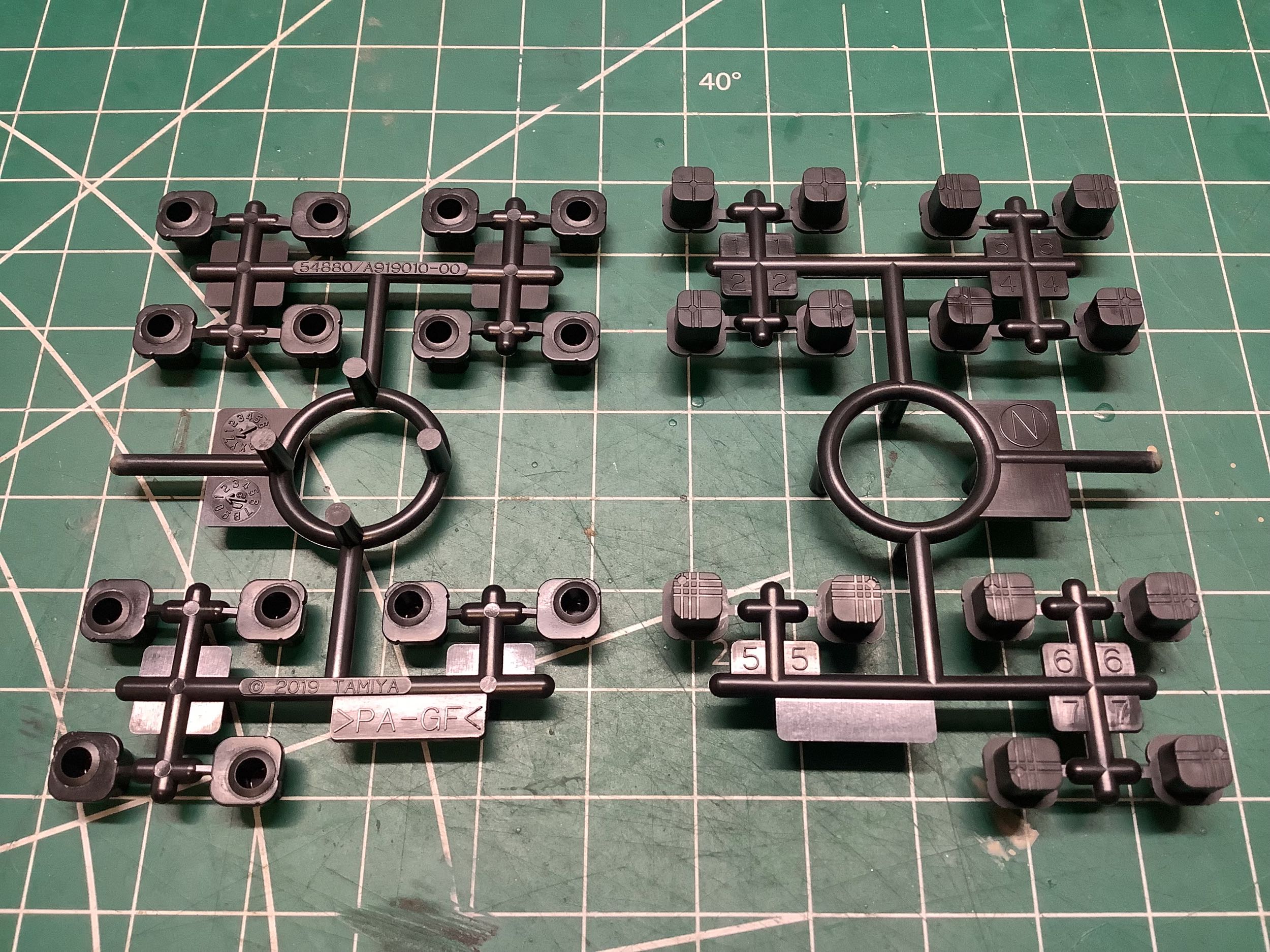
pulleys. On the right you can see the N-parts and V2-parts which
were also new in 2019 but were available in places other than the TRF
420 kit. The N-parts are the inserts for the new suspension mounts
and are marked with 54880
which is a separate aluminum adjustable suspension mount kit compatible
with many chassis but standard on the TRF 420. Much more on that
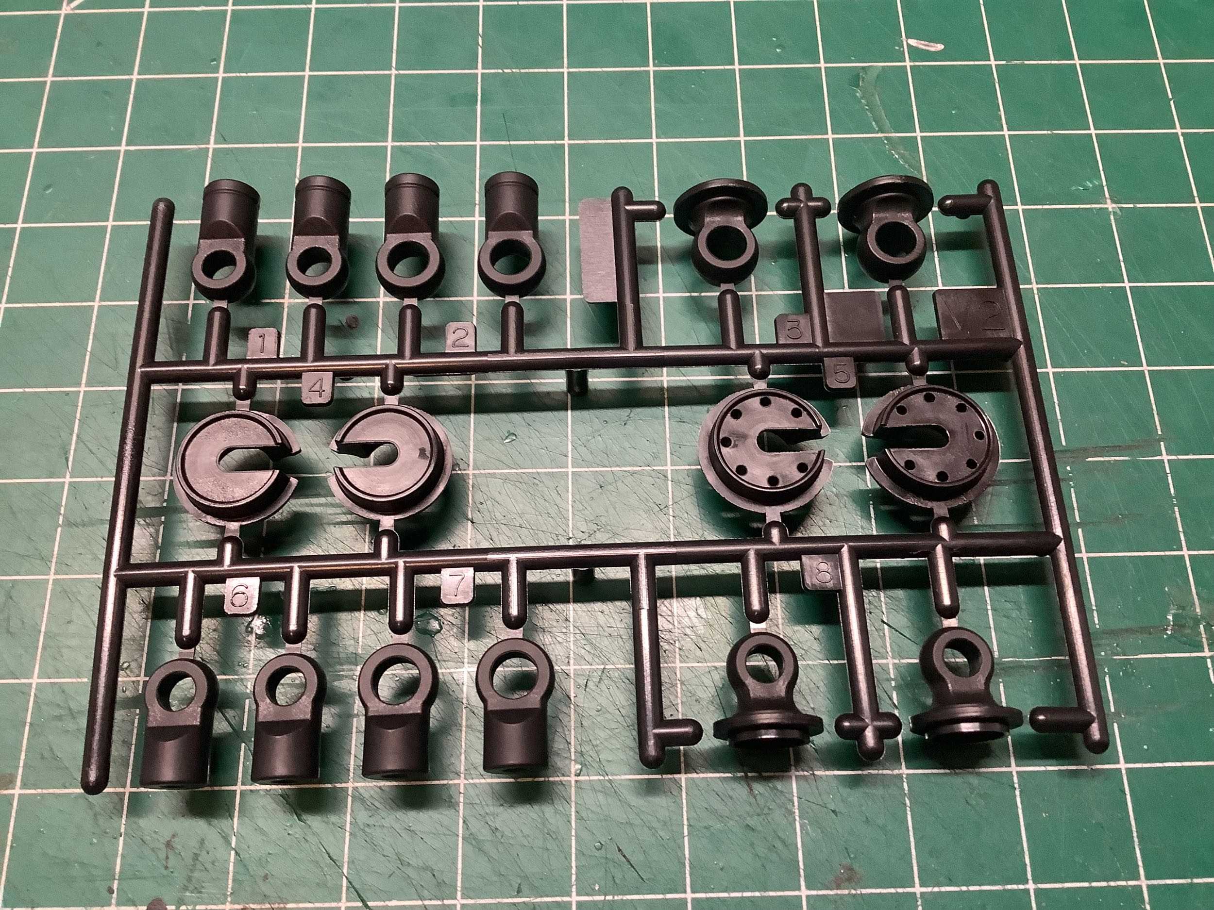
later. The V2-parts are updated TRF damper parts and are
marked with 54871
because they were available as a retrofit for older
dampers. They include strengthened rod ends for both the
original 5mm balls and the updated 5.8mm balls and spring perches for
two different spring sizes.
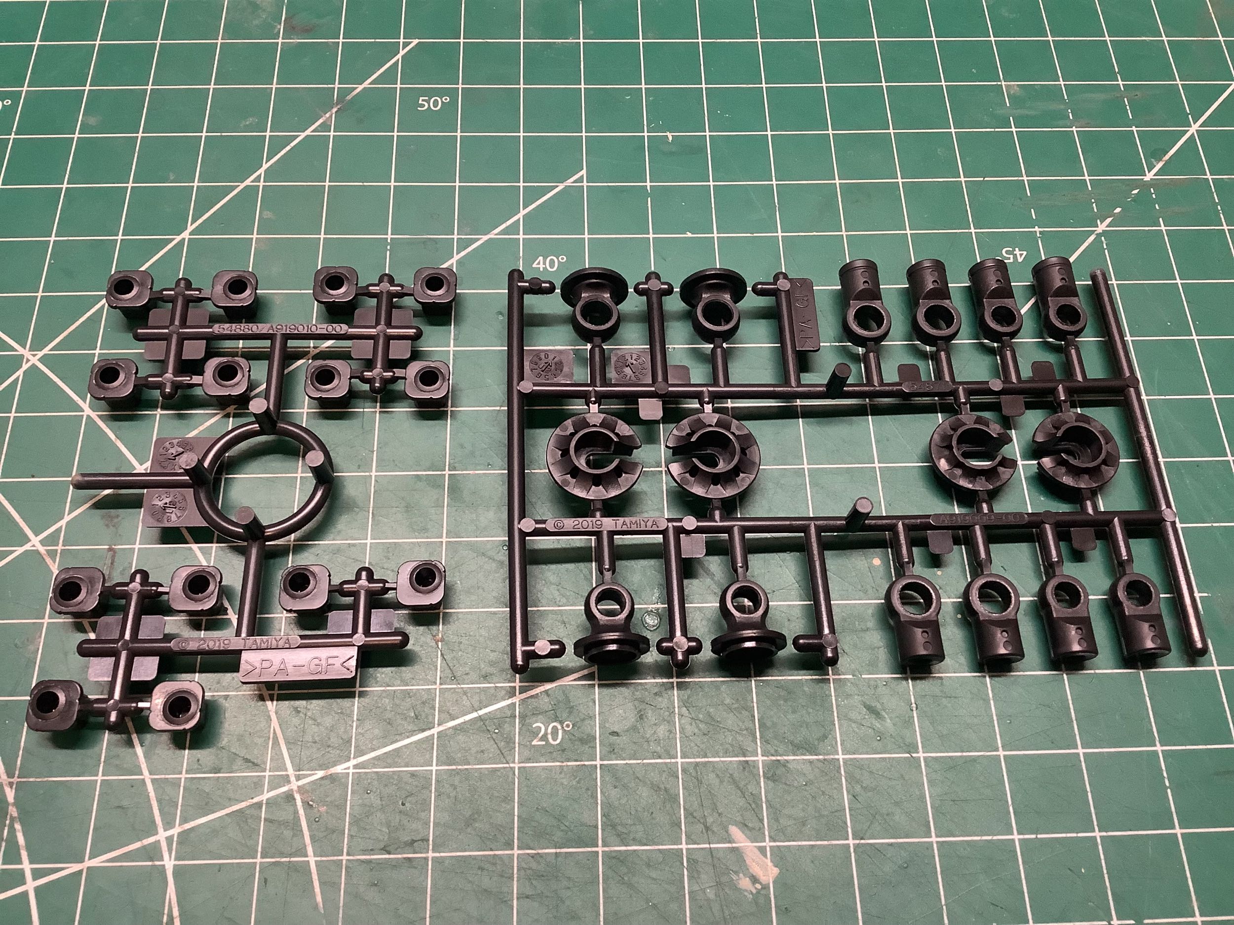
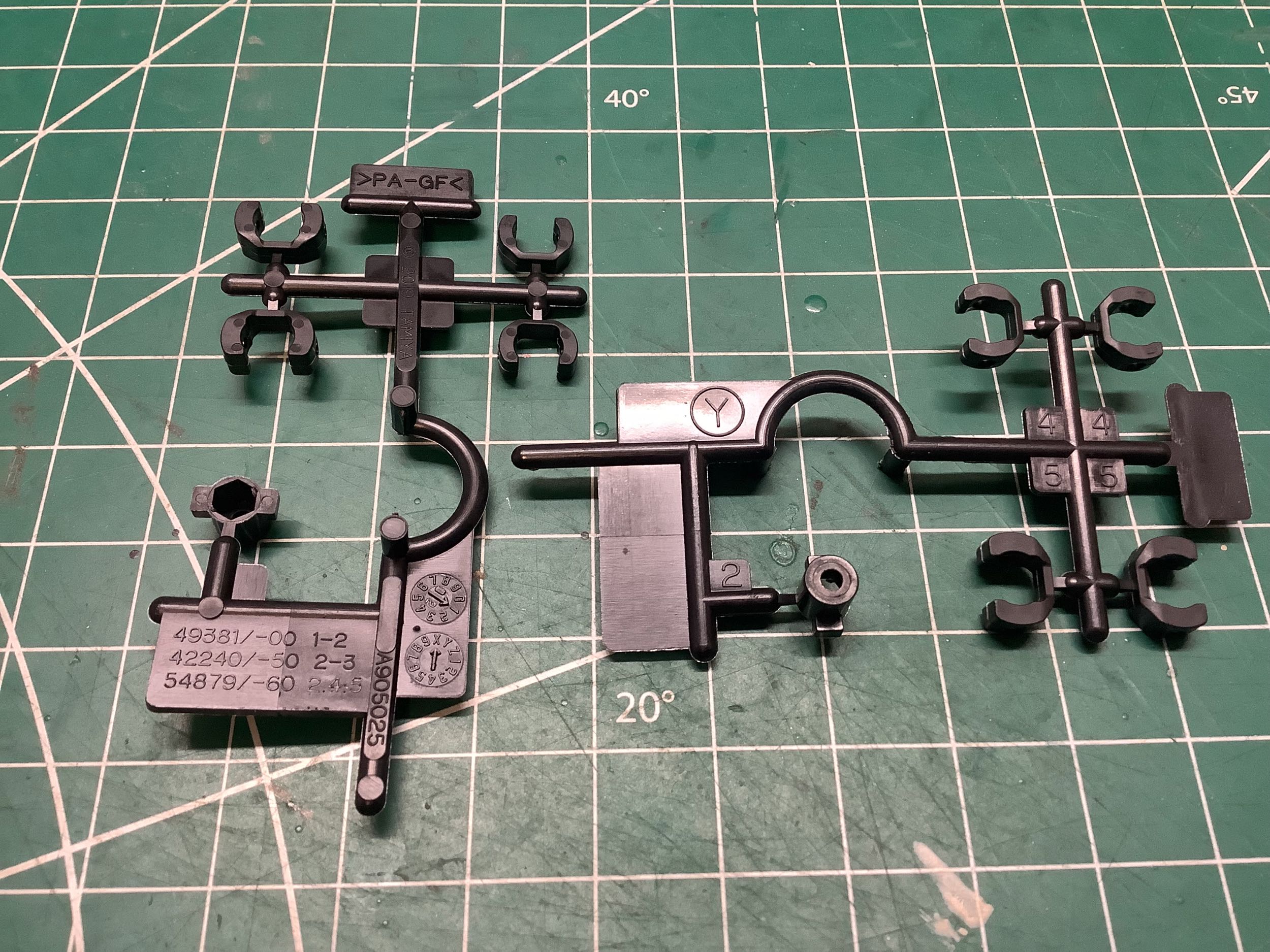
The Y-parts are axle caps and diff nuts. Axle caps were previously
made from Delrin but these have changed to glass filled Nylon. It
is quite odd that this sprue is marked with three different set numbers
and apparently each set came with only a portion of the overall
sprue. The original kit number is 49381
which was the TRF 415MSX from way back in 2005 and included 4 copies of
Part 1 (the axle caps) and 1 copy of Part 2 (the diff nut). The
first update came with kit number 42240
which was the TRF 417V5. It still included 1 copy of Part 2 (the
diff nut) but swapped to 4 copies of Part 3 (a modified axle cap).
The latest update is marked with 54879
which is a front spool upgrade for the TRF 419. This was
apparently when the material change happened. The Part 2 (diff
nut) stayed the same, but the axle caps changed again this time with 2
copies of Part 4 and 2 copies of Part 5. These caps seem to have
different thicknesses. The thinner parts are used on the rear axle
and the thicker parts on the front axle of the TRF 420.
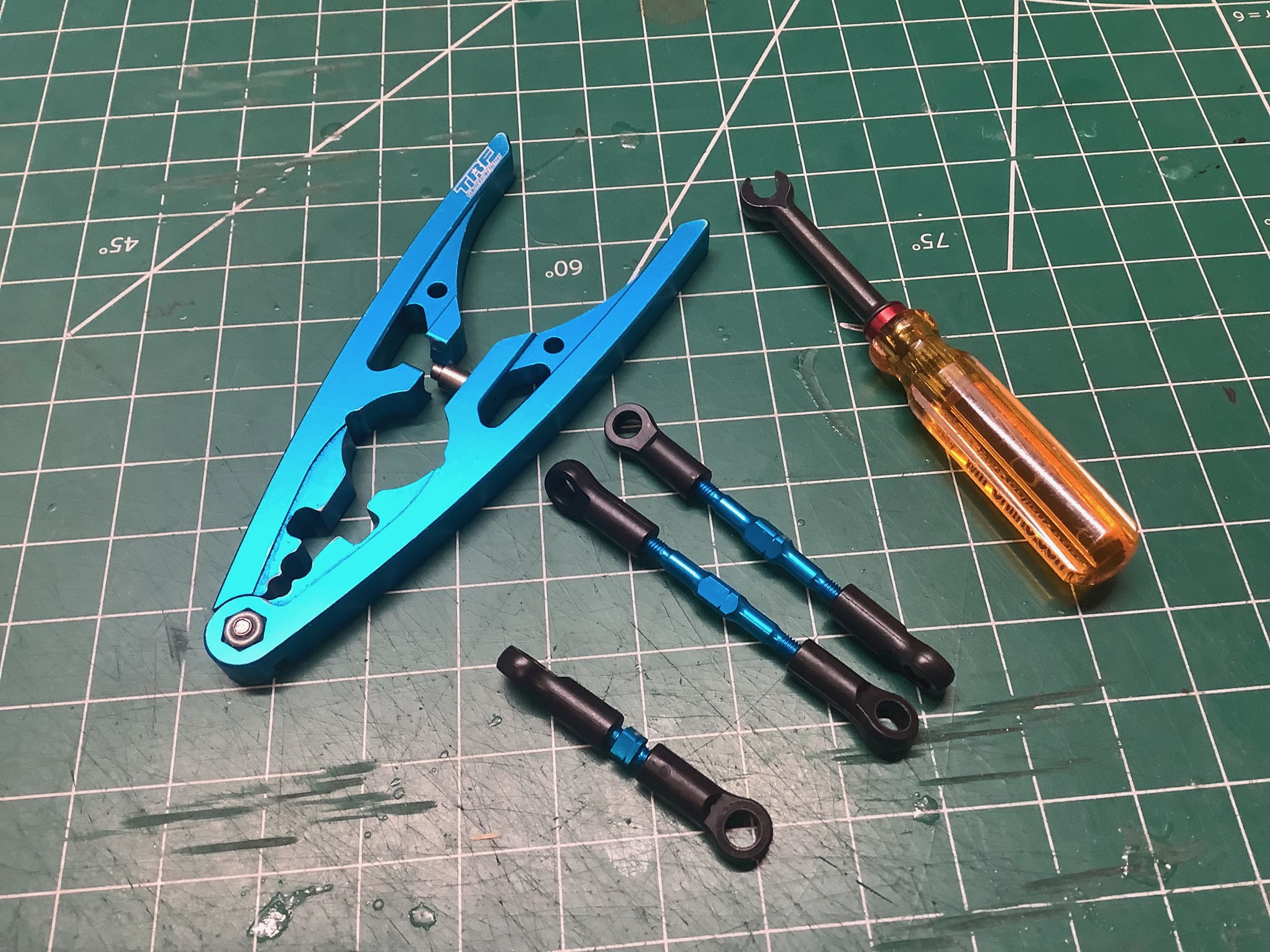
The 5mm ball adjusters had been the same forever, but these new parts (54869) are stronger and open on both sides. The odd looking parts on the right are the 54870 sway bar 5mm ball adjusters. They seem needlessly complex to me.
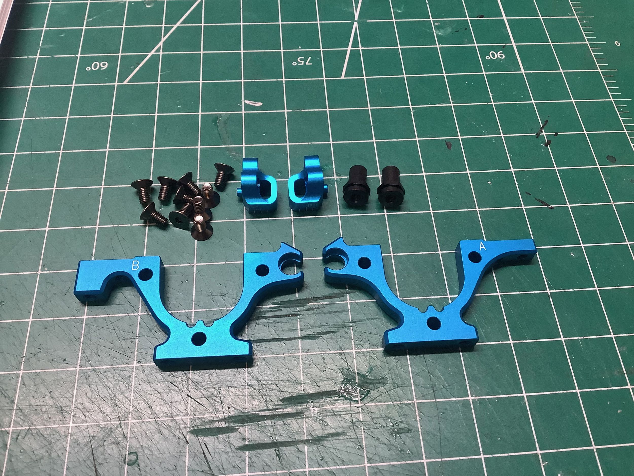
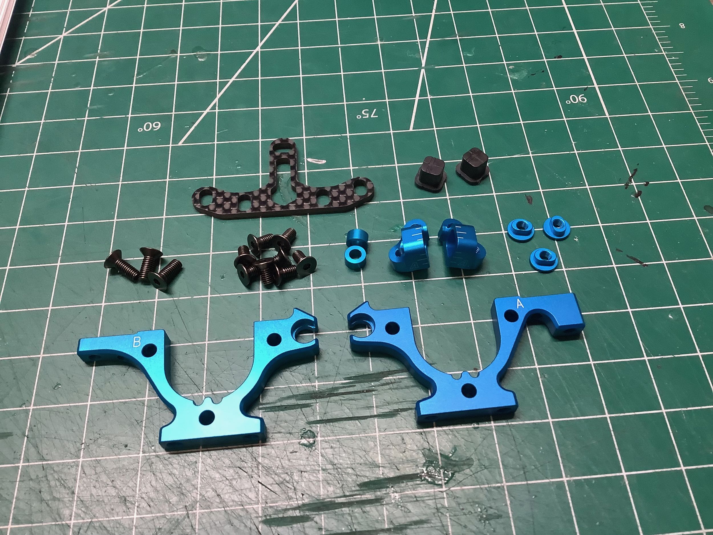
These parts are all new for the TRF 420 series, and the front bulkheads
have been altered even further for the 420X by changing the way the sway
bar bearings attach. More on that later. A close look at
the image on the left will show that I incorrectly used one front and
one rear bulkhead here because I didn't notice that they were
different. The one marked "B" on the far left is actually for the
rear and has a wider end. More on that later as well. Since I
have a whole pile of TRF chassis on display and they all use a carbon
deck, I decided to use the optional aluminum deck for my build. It
has a lot of cutouts as you can see.
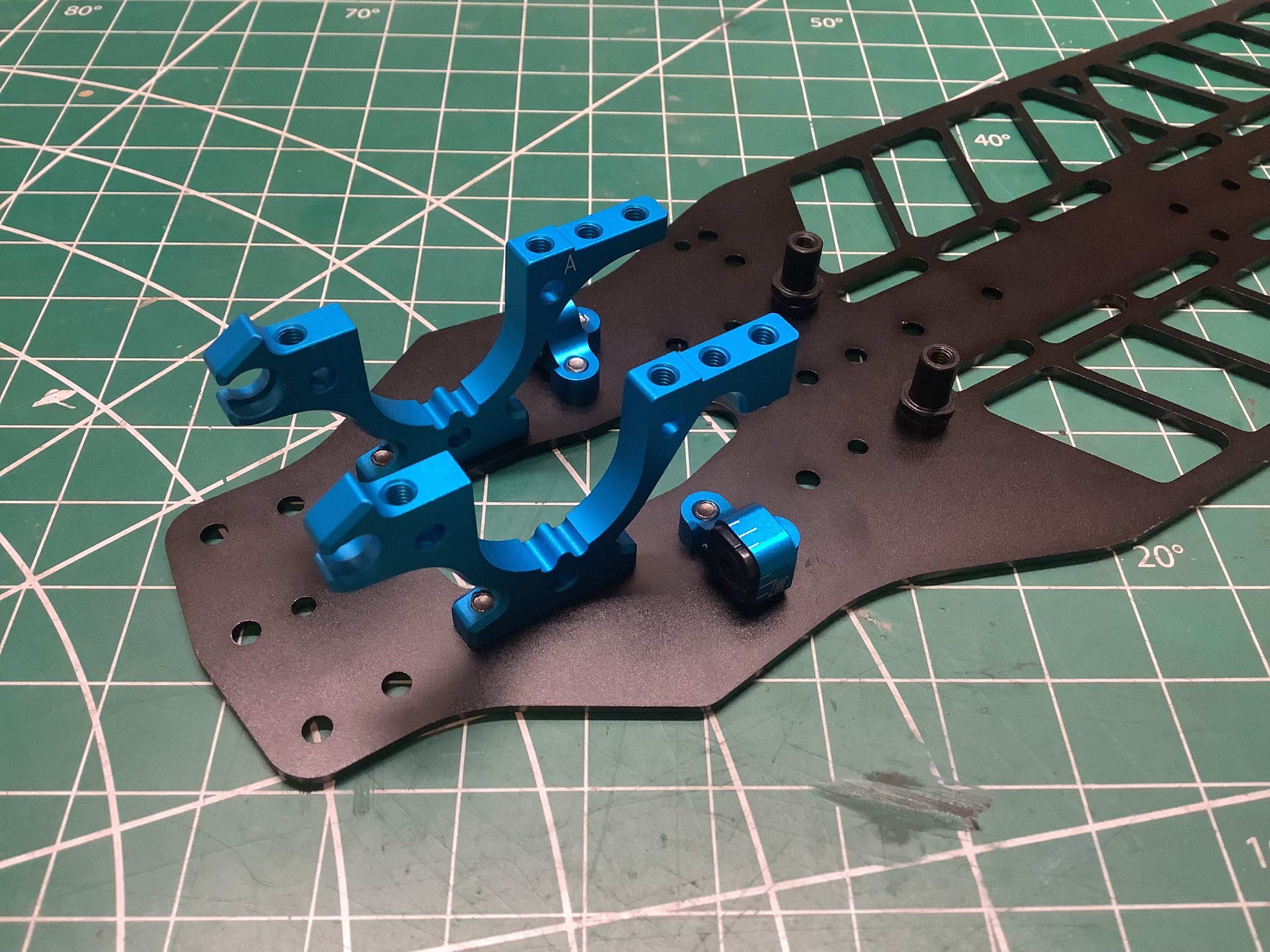
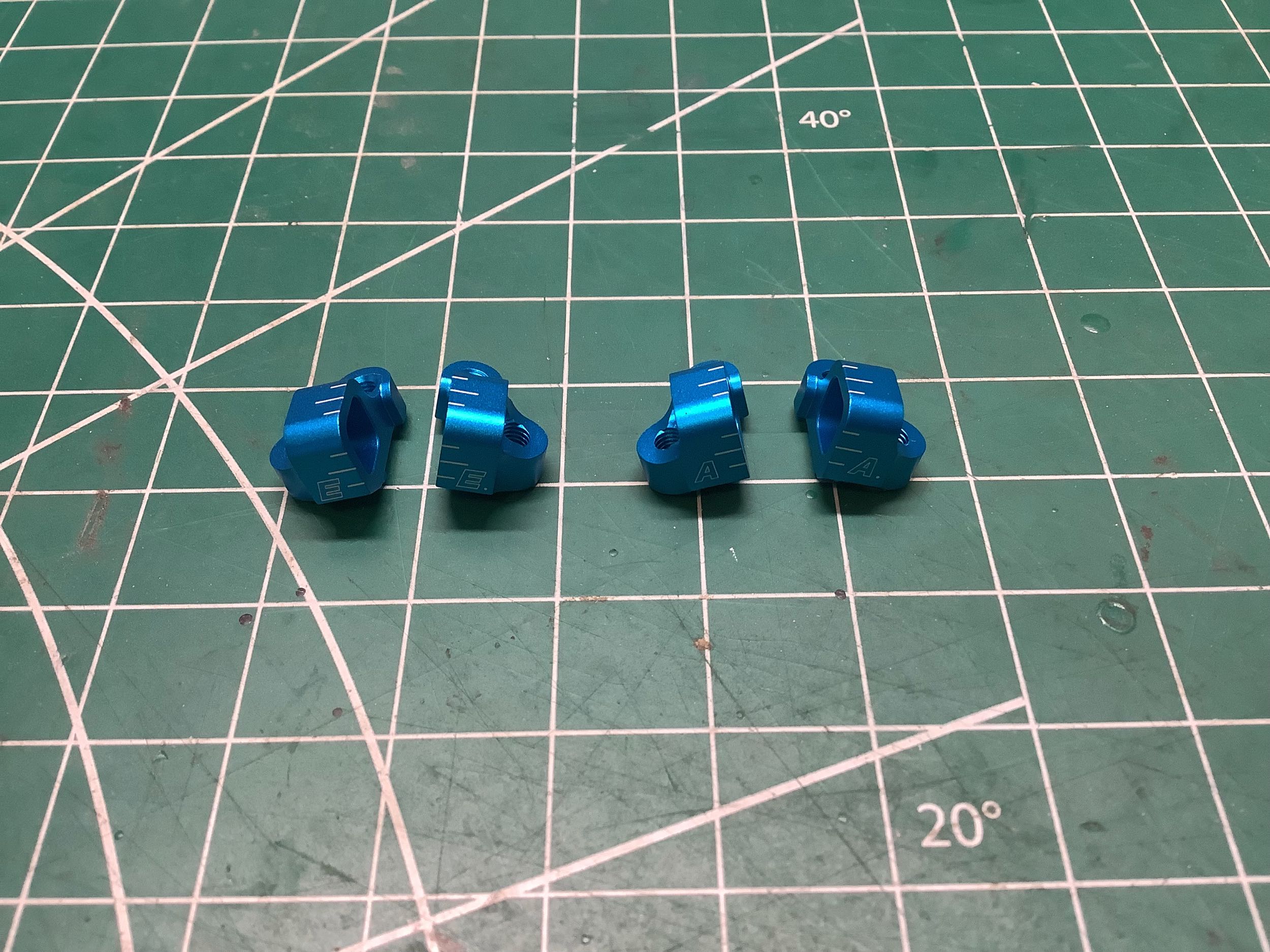
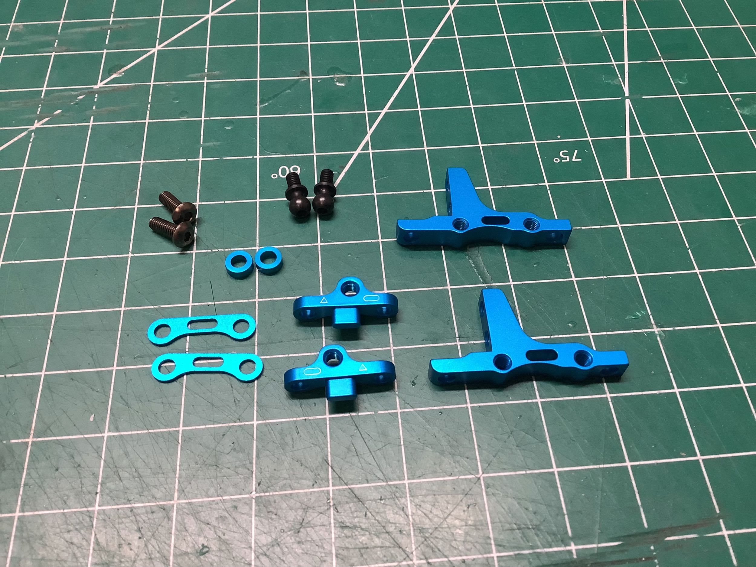
These new suspension blocks are probably the most significant change
introduced with the TRF 420 series. The corner split blocks seem
at first glance similar to those from the TRF 419, but they now have
plastic inserts (shown at right) which allow a wide range of tuning
options. While changing toe angle, track width, roll center, skid angle, and
sweep angle is still possible by changing suspension blocks and adding
or removing spacers, even more adjustment is now available by changing
inserts. The inserts have a centered hinge pin hole by default,
but also include optional offsets of 0.375mm or 0.75mm either vertically
or laterally meaning that there are 7 different insert pairs with 25
different position options at each corner. That's almost 400,000
ways to combine the options at all four corners of a suspension setup if
you don't require that only matched sets be used, or more practically
625 combinations by matching inserts left to right. That's with a
given set of suspension blocks, but those are also replaceable.
Seems like an adequate number of options. I used the manual
defaults.
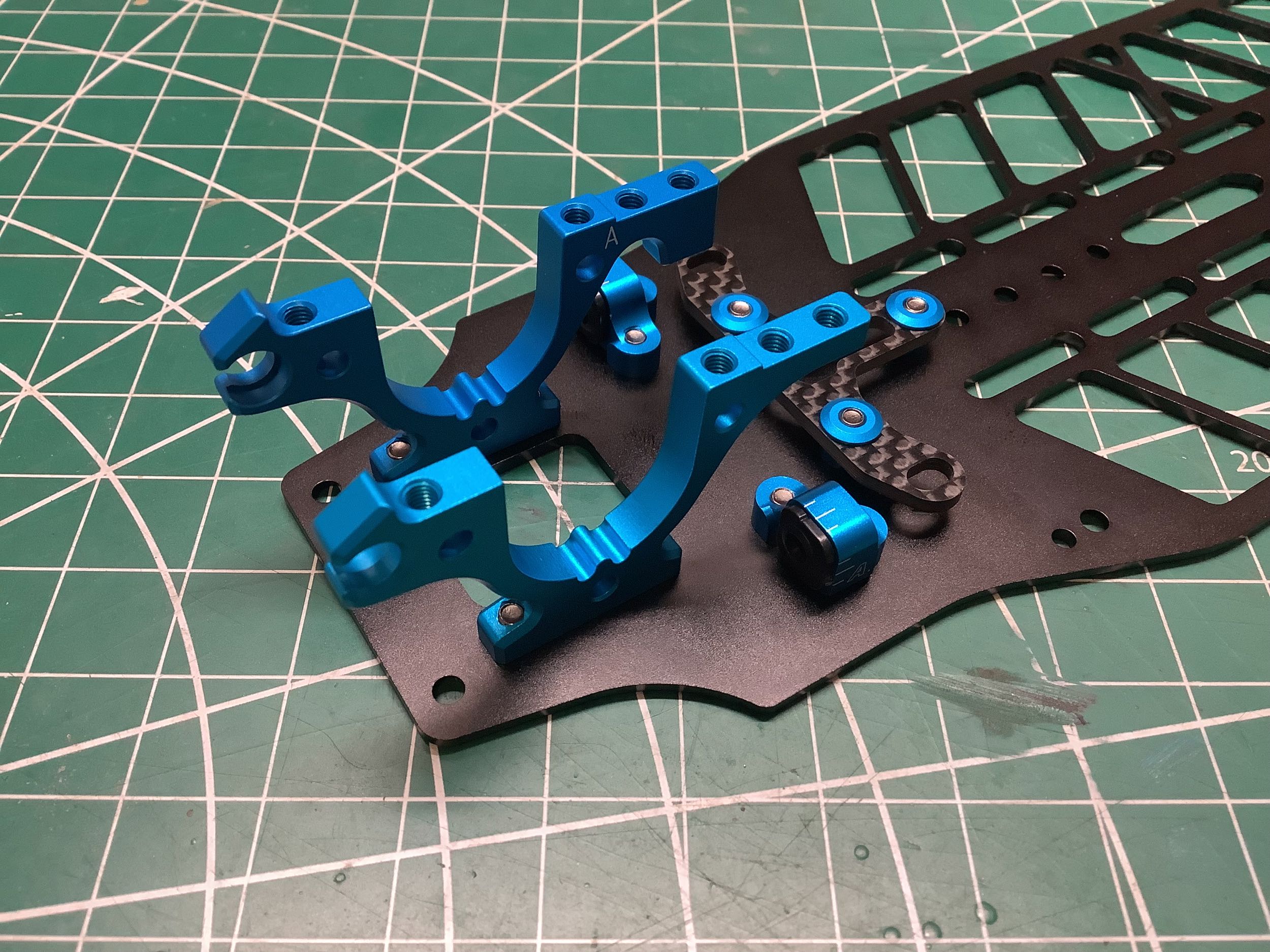
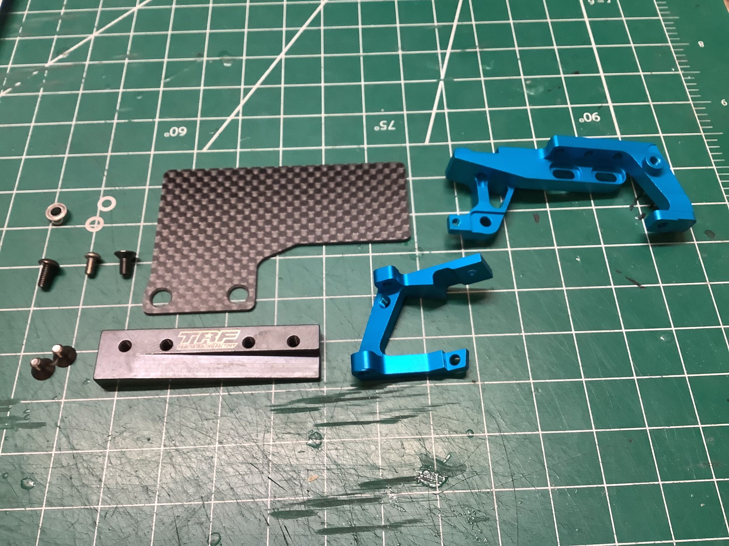
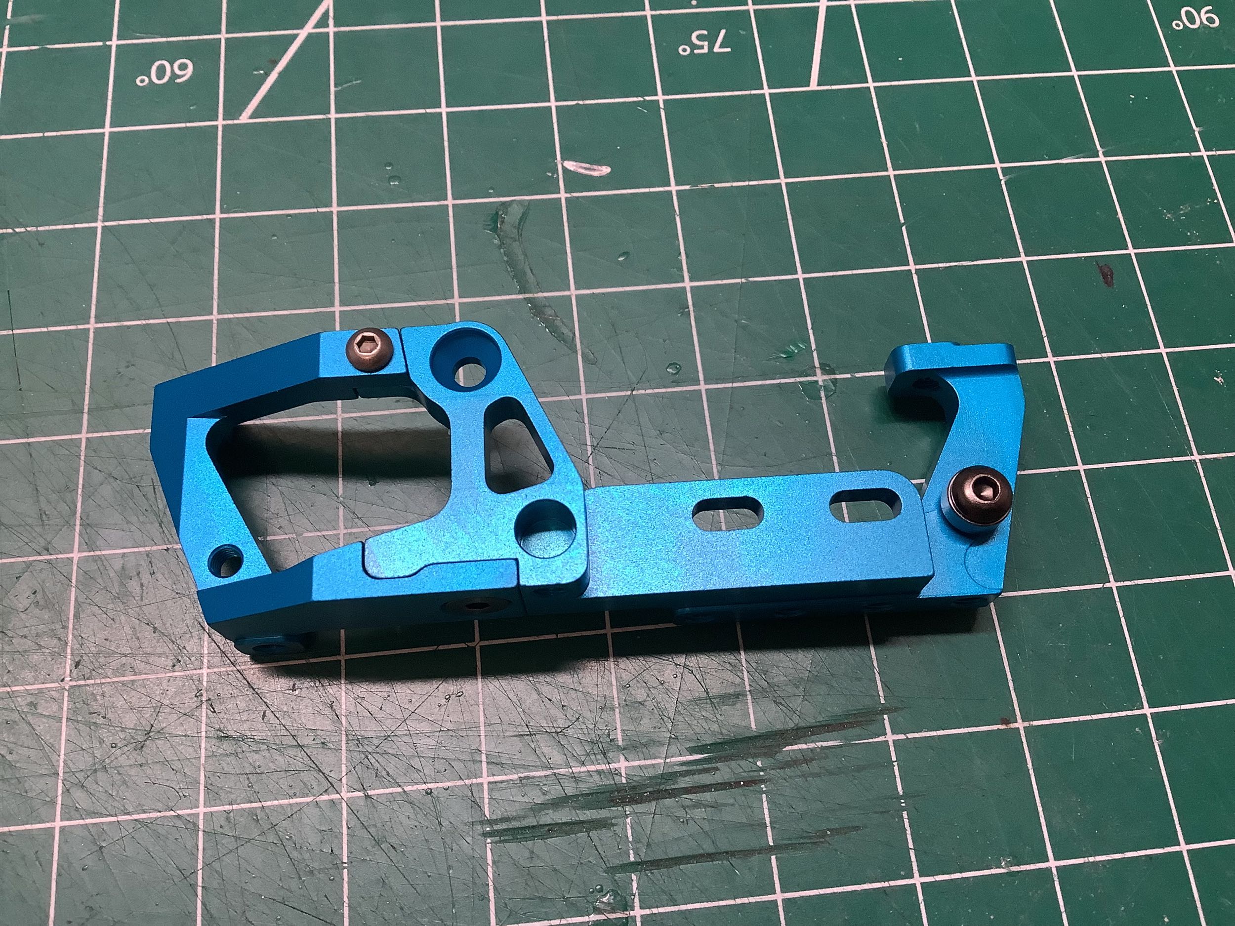
Here are the rear bulkheads which are shown not matching because I
hadn't figured out my error yet. The one marked "A" is the correct
part for the rear. The only difference is the thicker tab on the
right of the left image. Out of the box that tab doesn't do
anything, but the longer screw hole is there to accommodate an extra
link attached from the bottom is the optional rear toe control kit is
installed. It took me a long time to figure out what it was for
because it only appears in use in the options section of the
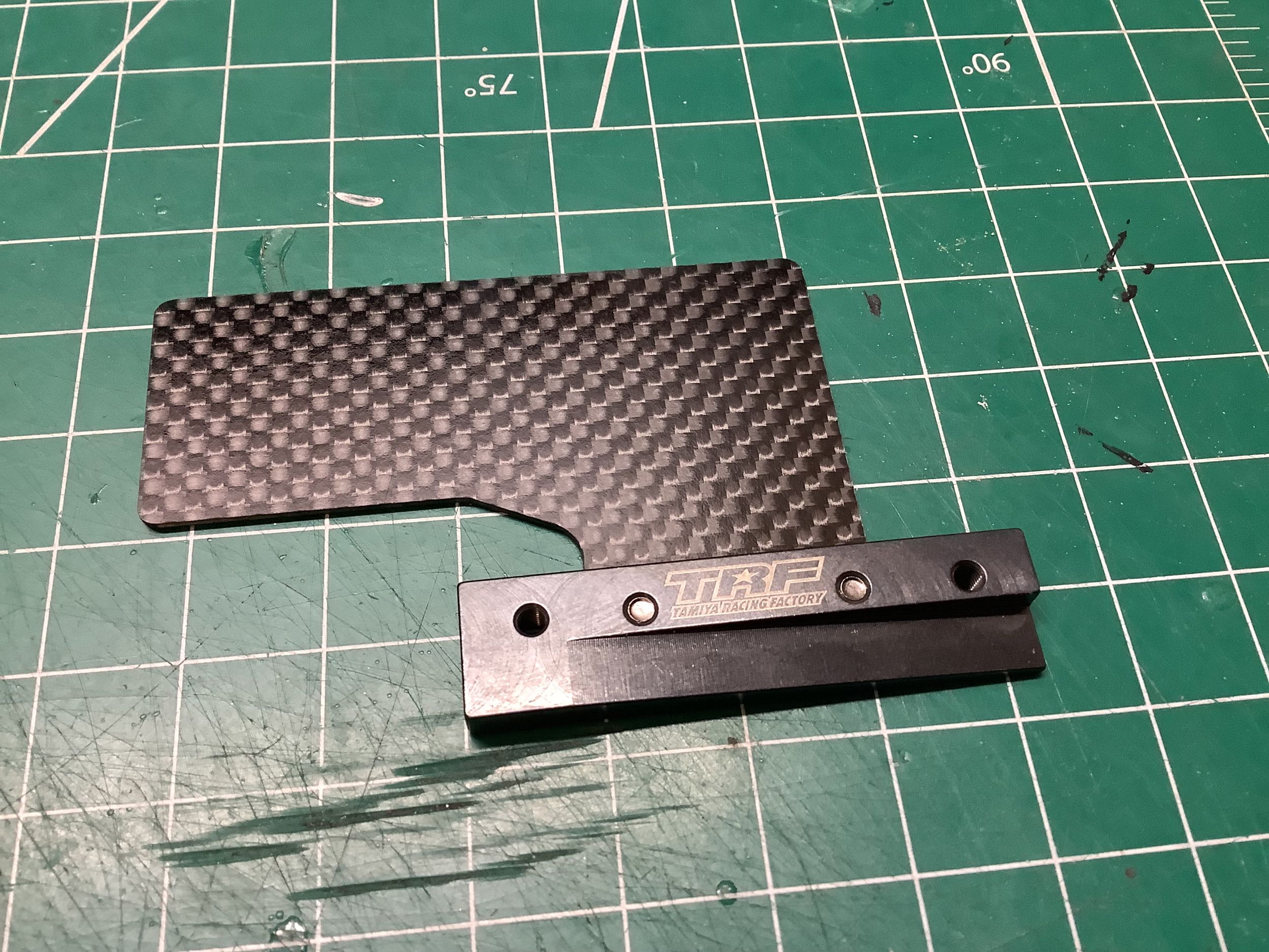
manual. That T-shaped carbon part is a chassis stiffener. It
is secured with 3 slotted aluminum inserts as shown on the right.
By default the inner holes are used, but the attachment can be changed
to the outer holes for higher stiffness. This is new for the TRF
420X and did not exist on the 420. In the picture on the right,
you can also see the little white lines on the suspension mounts that
help you see which insert you have installed.
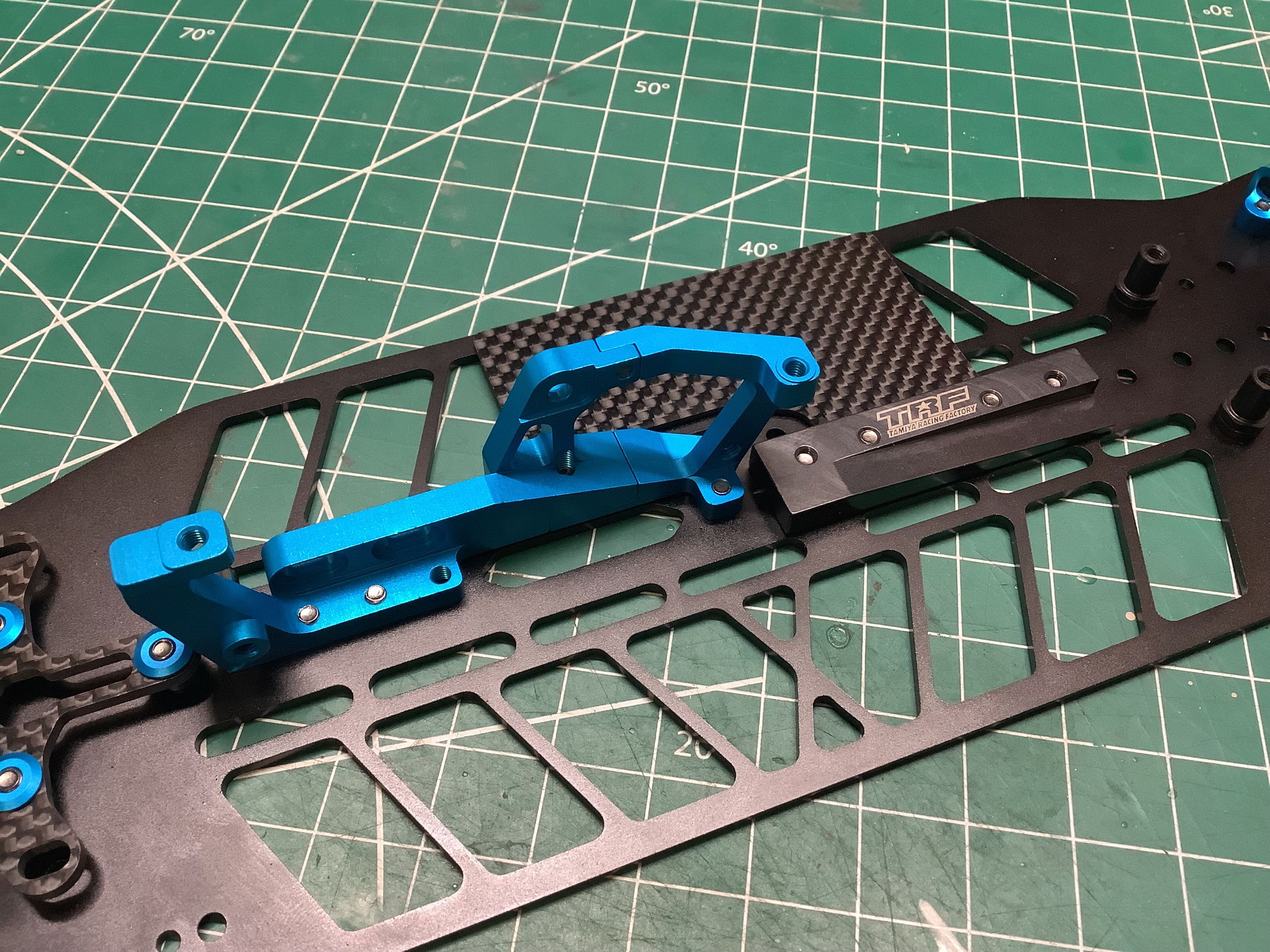
Everything here is also new for the TRF 420X. The TRF 420 used a
3-piece motor mount and center bulkhead. The 420X changes to a
2-piece mount which only supports the center shaft on one side.
I'll complain more about that later. The TRF 420 had an optional
52g center ballast weight, but the 420X changes this to a 20g weight
which doubles as a support for the carbon electronics deck. This
floating deck is only attached to the chassis on the center line so it
doesn't add any stiffness. If the ESC and receiver are attached to
this deck, they can be easily replaced without scraping off the servo
tape every time. Since the ballast supports the electronics deck,
it cannot be omitted without also omitting the deck. If using the
optional aluminum lower chassis like I am, there is really nothing to
attach the electronics to if you don't use the carbon deck because there
are so many cutouts.
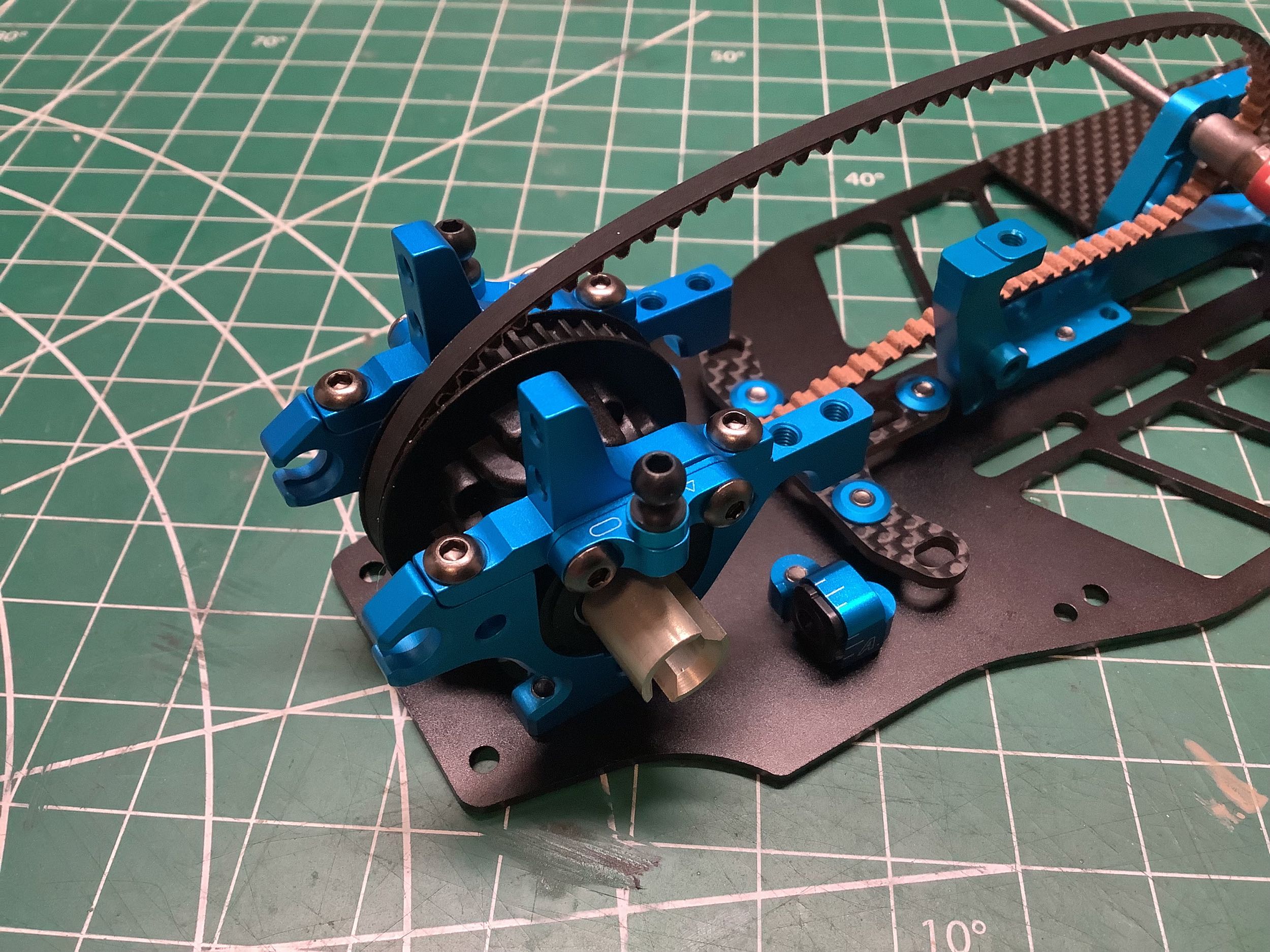
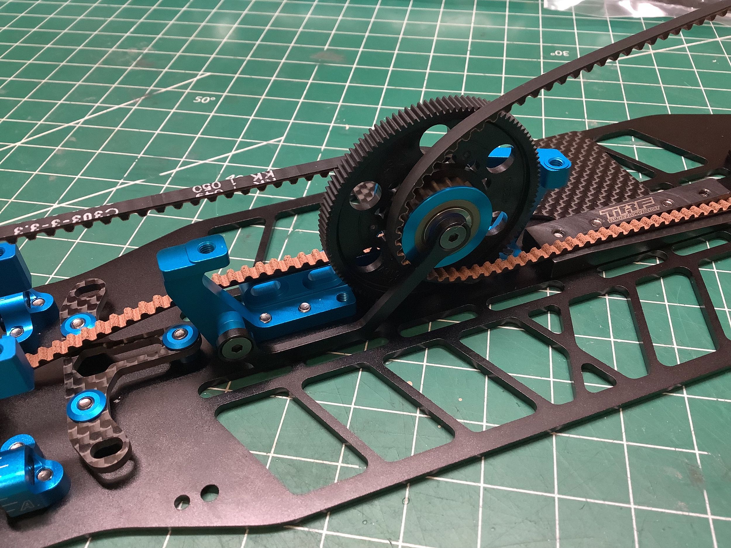
The center bulkhead and motor mount are shown at the left. That
screw you see at the right of the image supports some bearings that
route the belt very carefully away from the motor (different diameter
bearings are used based on rear differential attachment height).
This did not exist on the TRF 420 and the reason it is necessary here is
that the center pulley has moved from aft of the motor to forward of
the motor. The motor position itself has not changed, but the
position of the center pulley has which means the rear belt is now much
longer and has to clear the motor and the pinion. More on this
later.
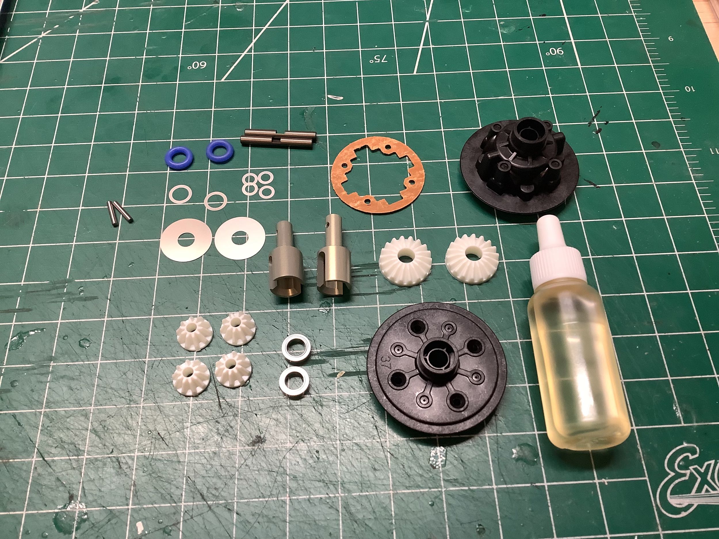
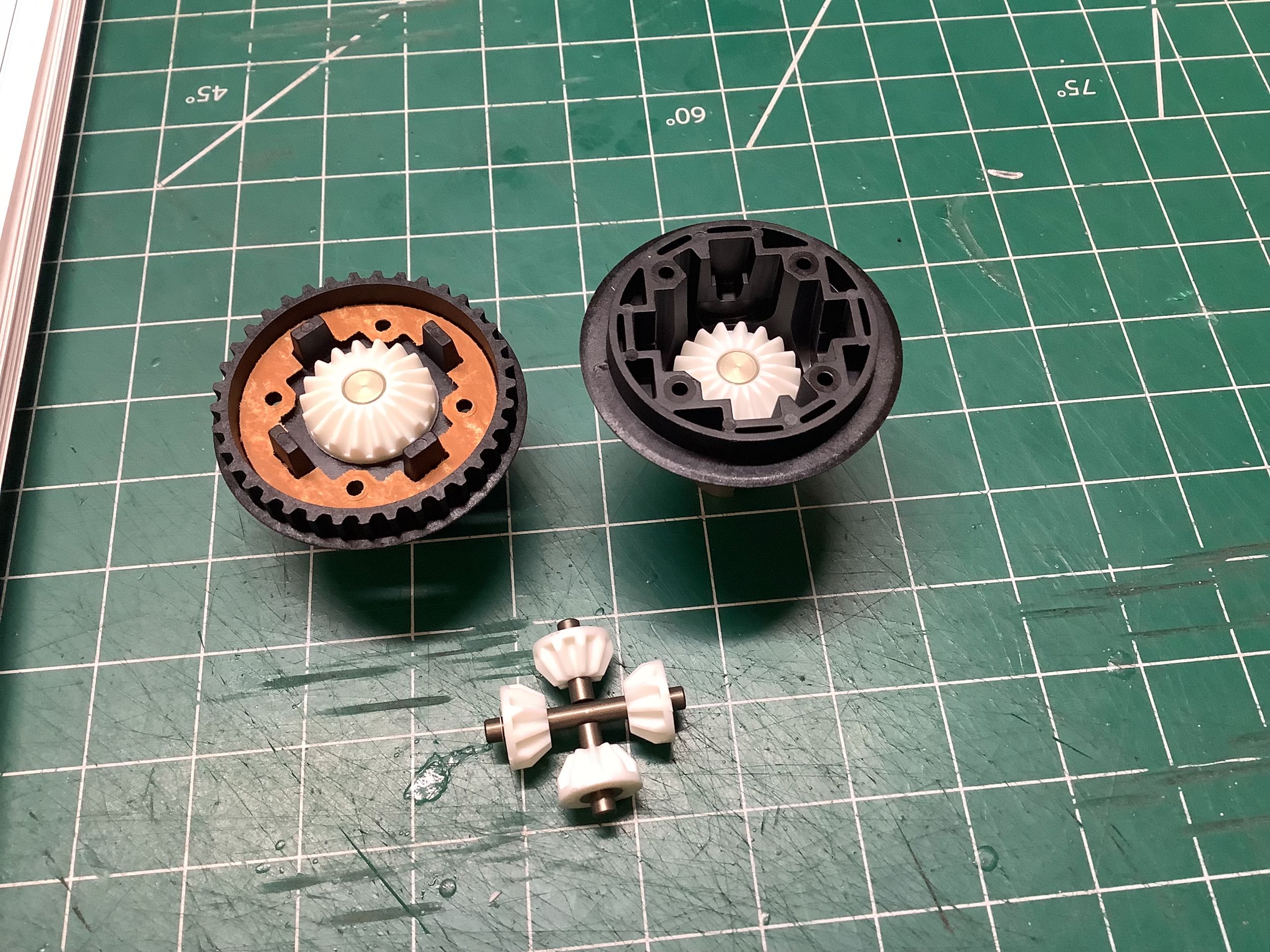
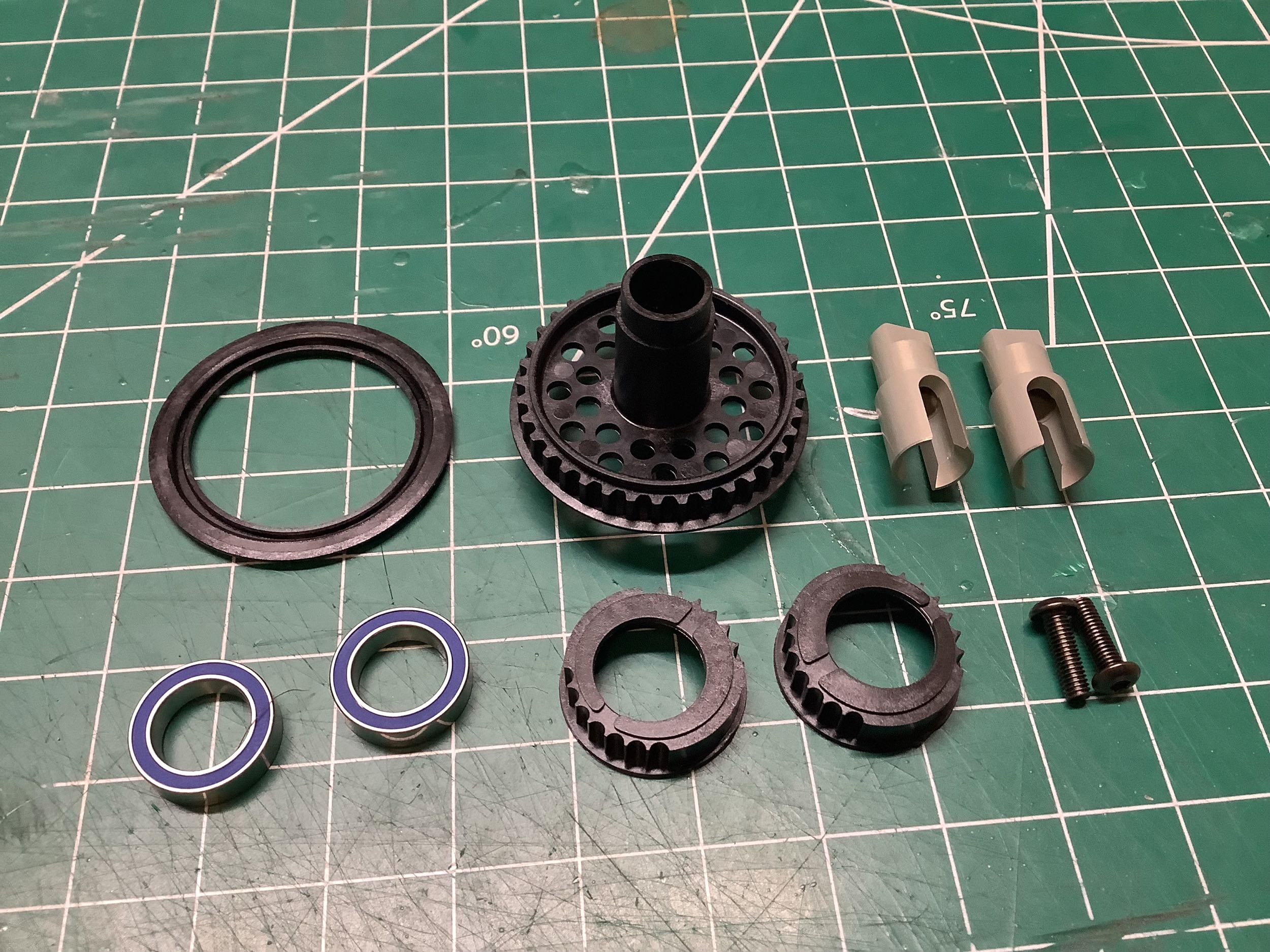
This sealed gear differential is carried forward from the TRF 419, but
the TRF 420 uses much more viscous #3000 oil instead of #900. The
gears and housing have remained the same.
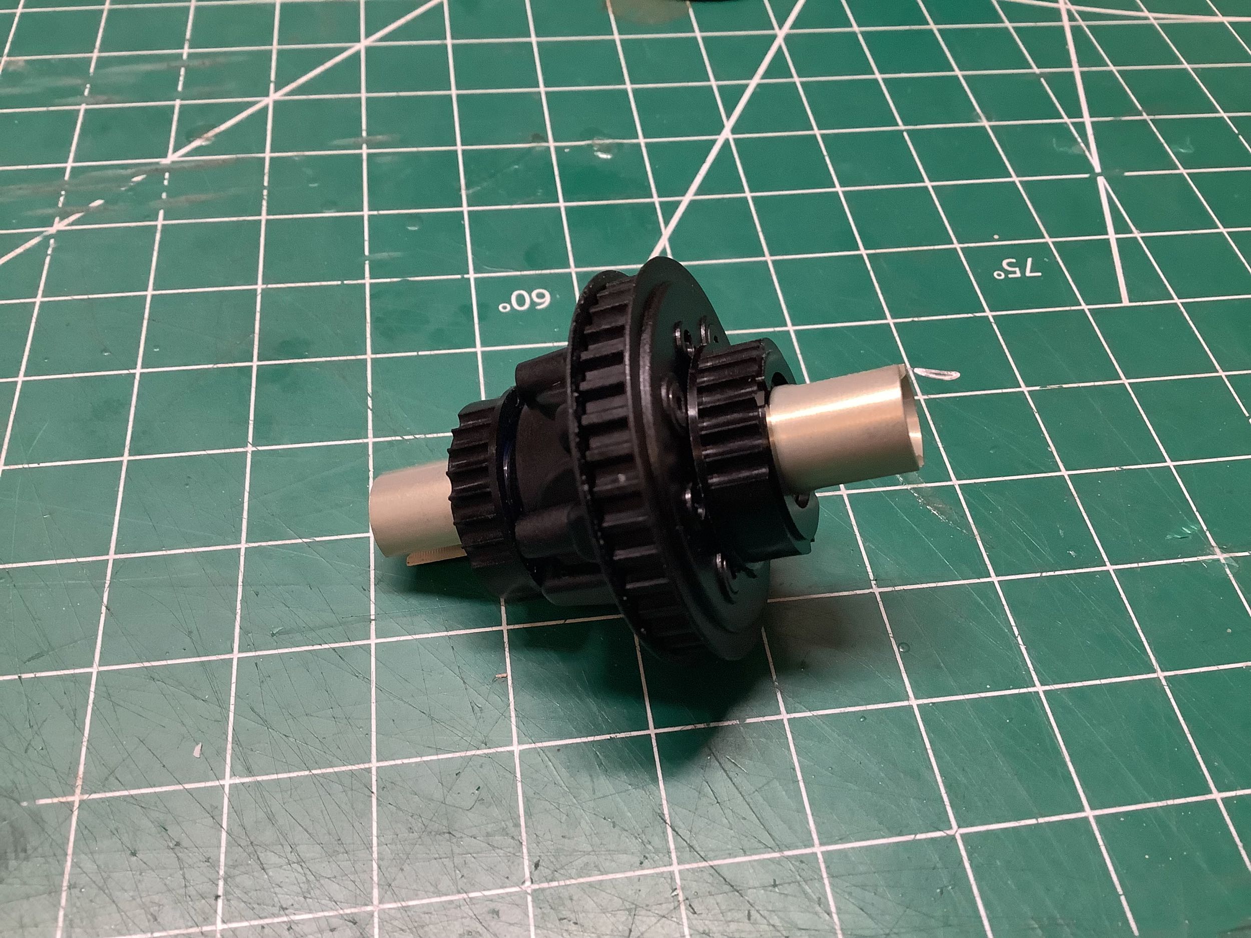
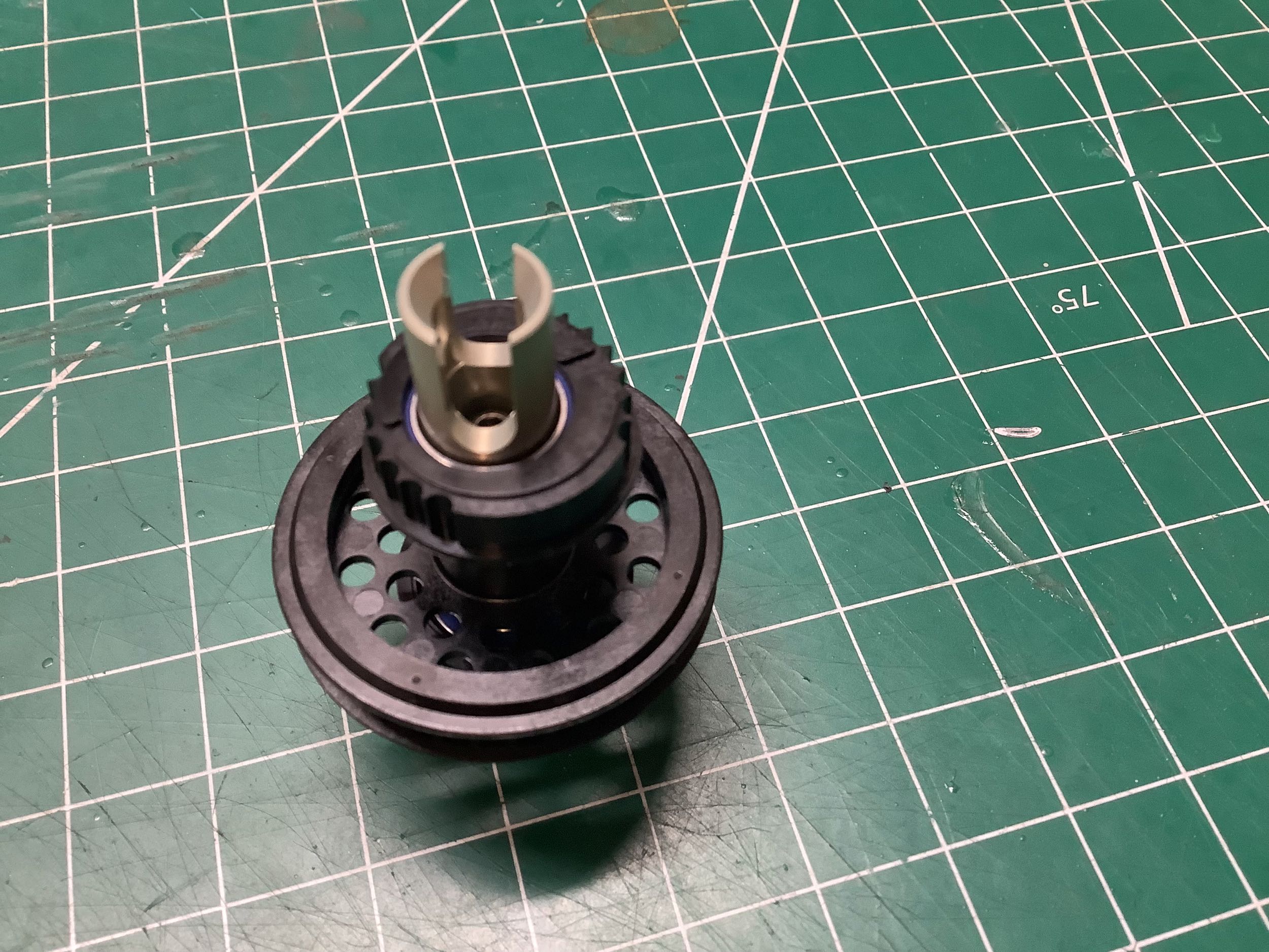
This image of the completed rear differential assembly shows the new
strengthened K parts (the cam shaped bearing supports that adjust belt
tension and differential height).
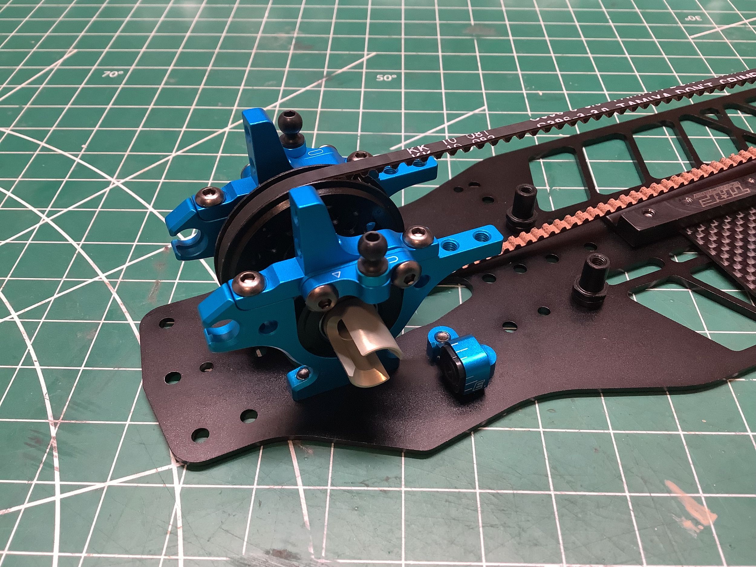
While the TRF 419 used one-piece upper bulkheads, the 419X changed to
separate upper arm mounts. By changing the spacers between the
upper bulkhead and upper arm mounts, the camber link position can be
modified. The same design is carried forward to the TRF 420
(although they don't share the same part numbers). 0.8mm spacers
are used here. Installation of the upper bulkheads locks in the
rear differential. (I've also fixed the incorrect lower bulkhead
here.)
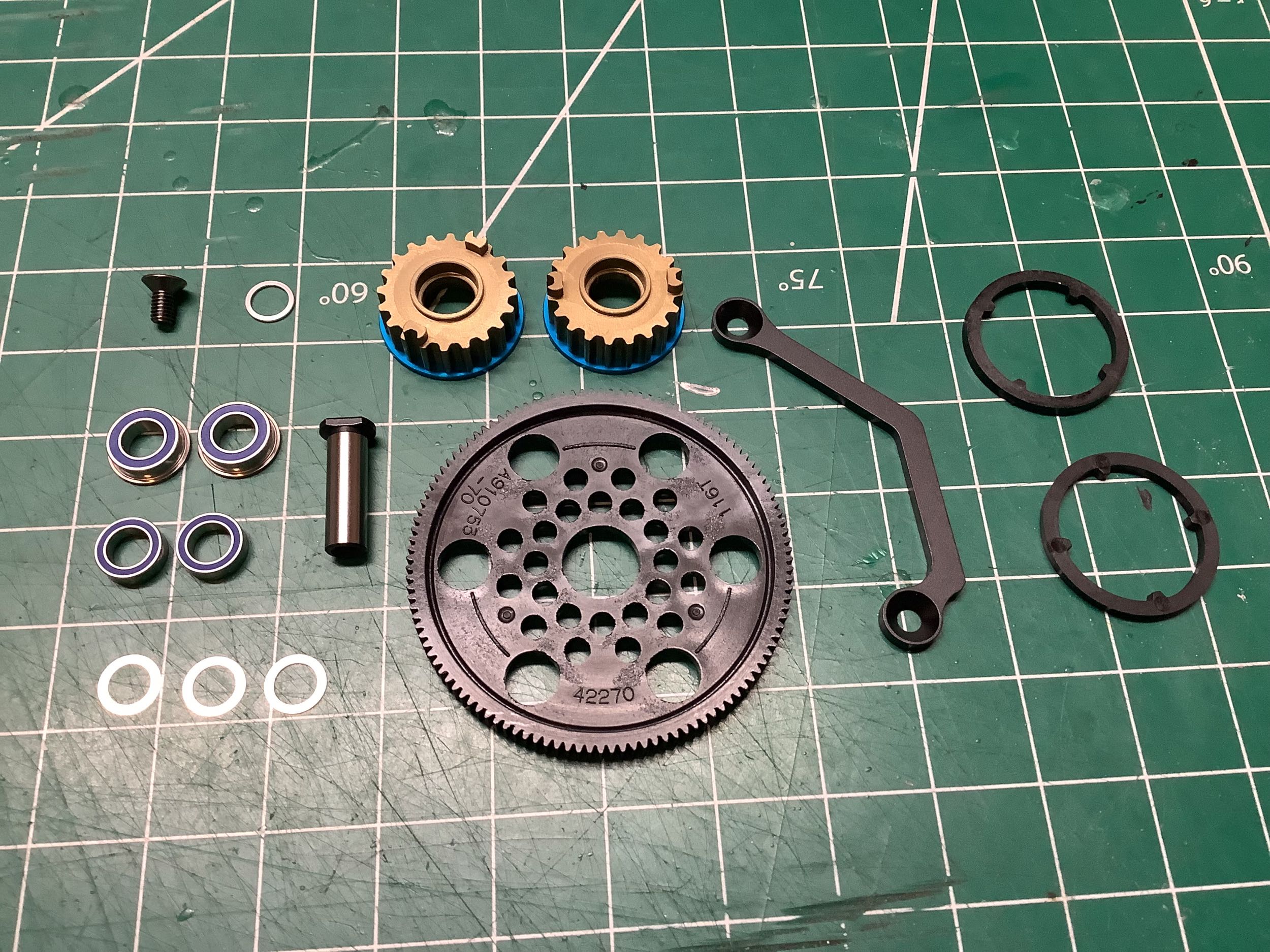
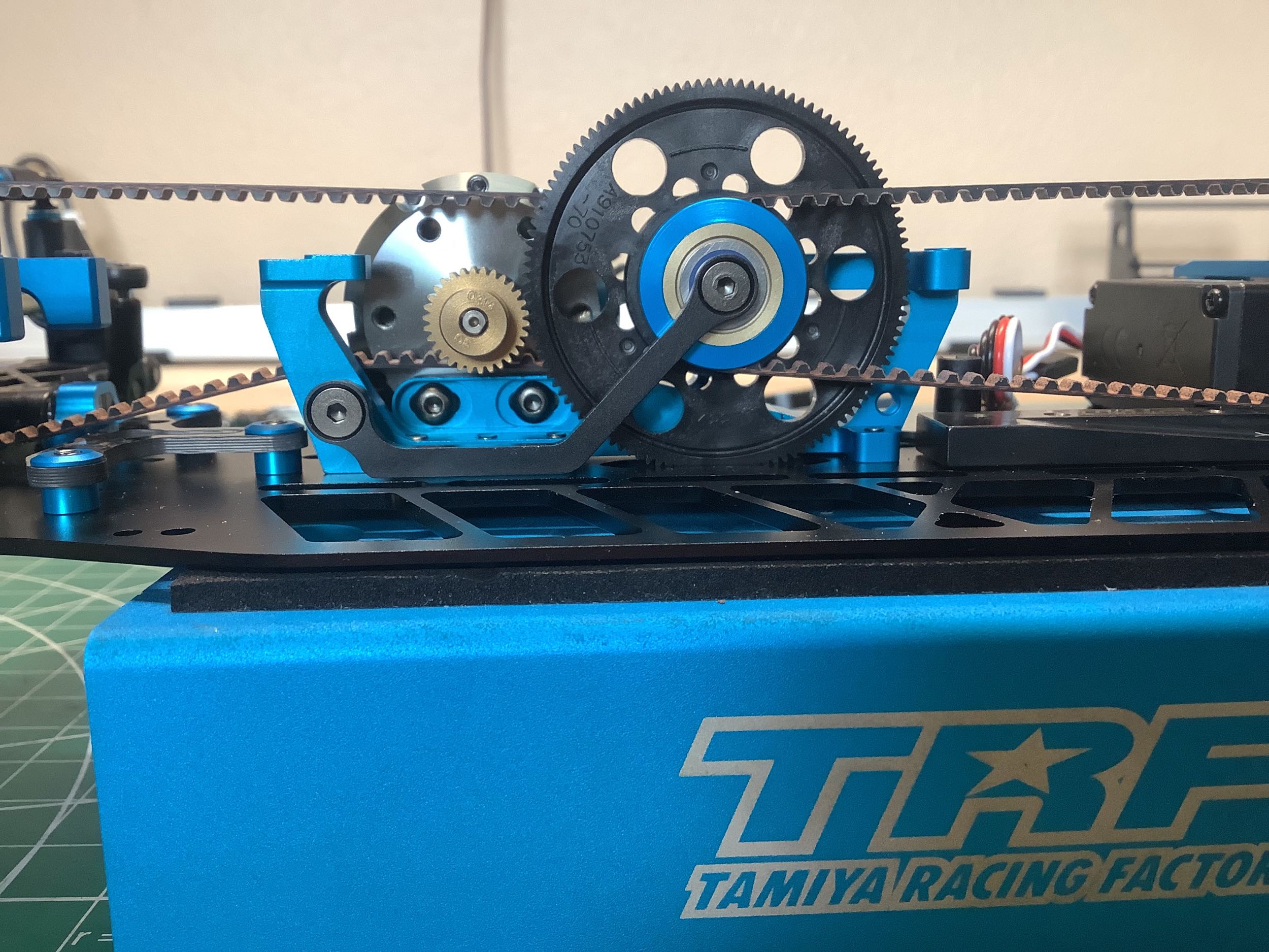
Here's a different type of support than we've ever seen before.
The same 116T spur gear is used as on the TRF 419, but the 20T pulleys
have separate plastic belt guards introduced on the TRF 420. The
even bigger change to the 420X is the steel "battery stopper" shown
here.
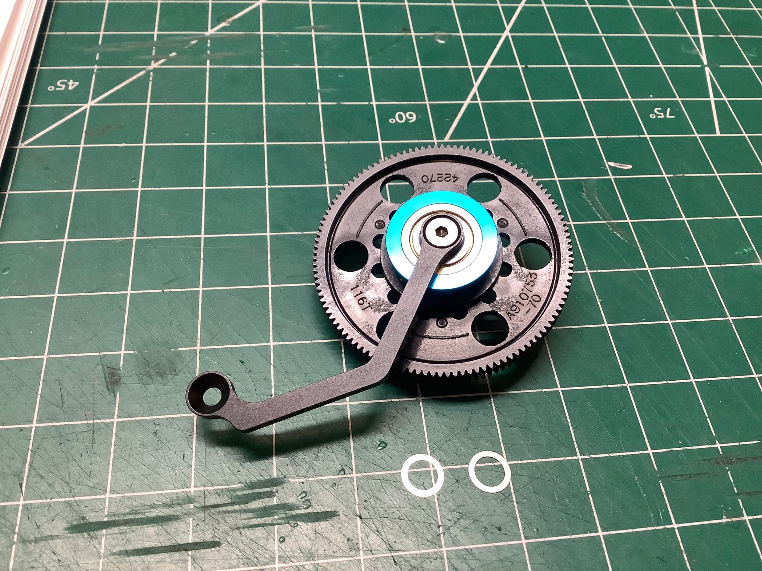
That angled link doesn't provide any vertical support at all to the
center shaft which means that the whole thing is effectively
cantilevered from the center bulkhead. My engineering brain
shudders at how terrible this idea is. Thankfully, having belt
tension on either side of the spur does at least a reasonable job of
balancing the forces. Tamiya correctly called it a "battery
stopper" because it's only real function is to keep the battery away
from the gears and belts.
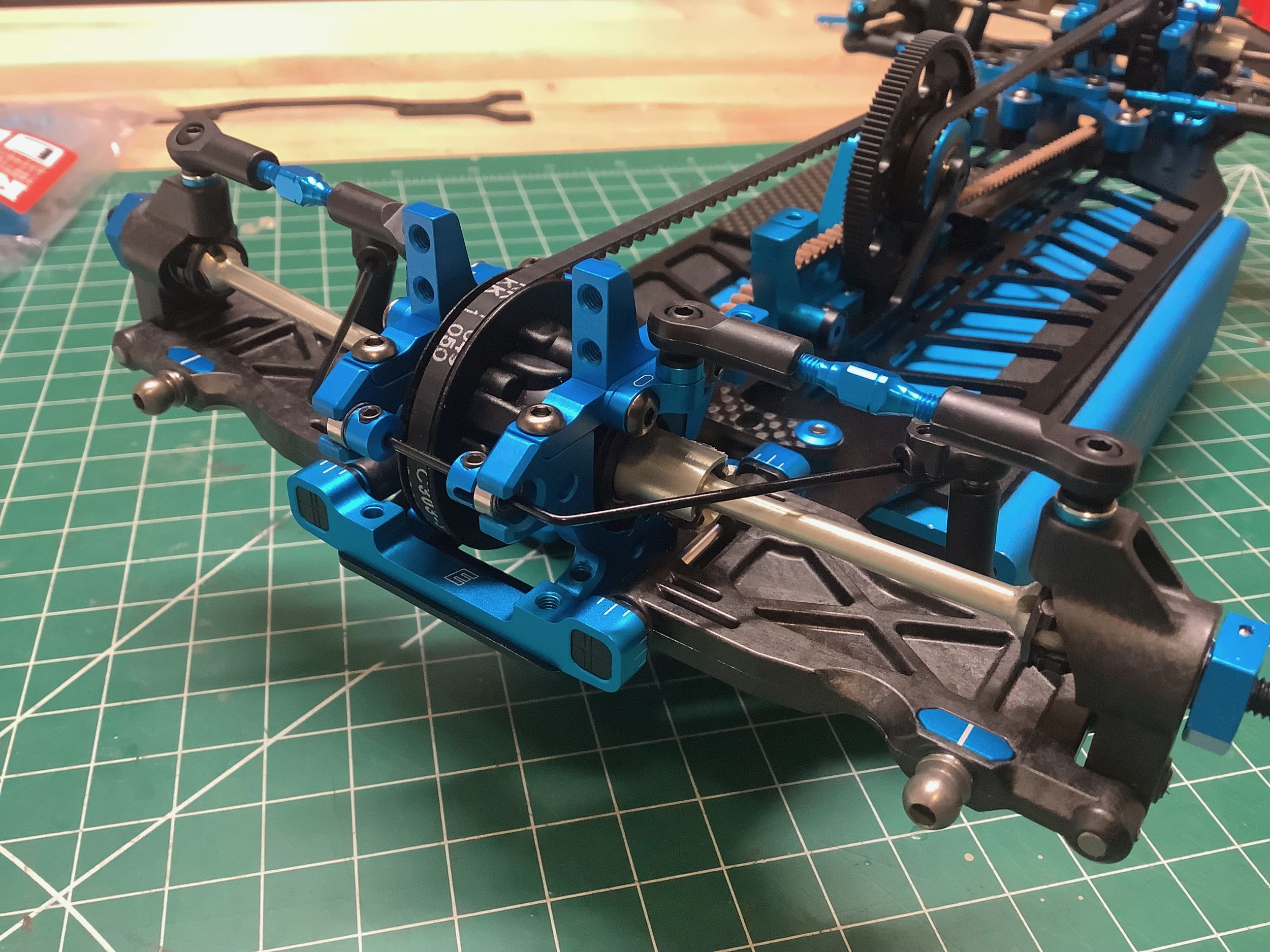
The plastic front spool is new for the TRF 420. All previous TRF
models used an aluminum insert for either the one-way or locked spool to
attach to the front pulley. The TRF 420 is the first model to
incorporate the spool directly into the pulley. The aluminum drive
cups slot into the spool and are secured with screws. This seems
much less robust than previous chassis to me, but I suppose it is
lightly and has less rotating inertia. The pulley itself uses two
parts with a separate belt retainer, but unlike some previous versions
this part snaps into place and does not require any glue.
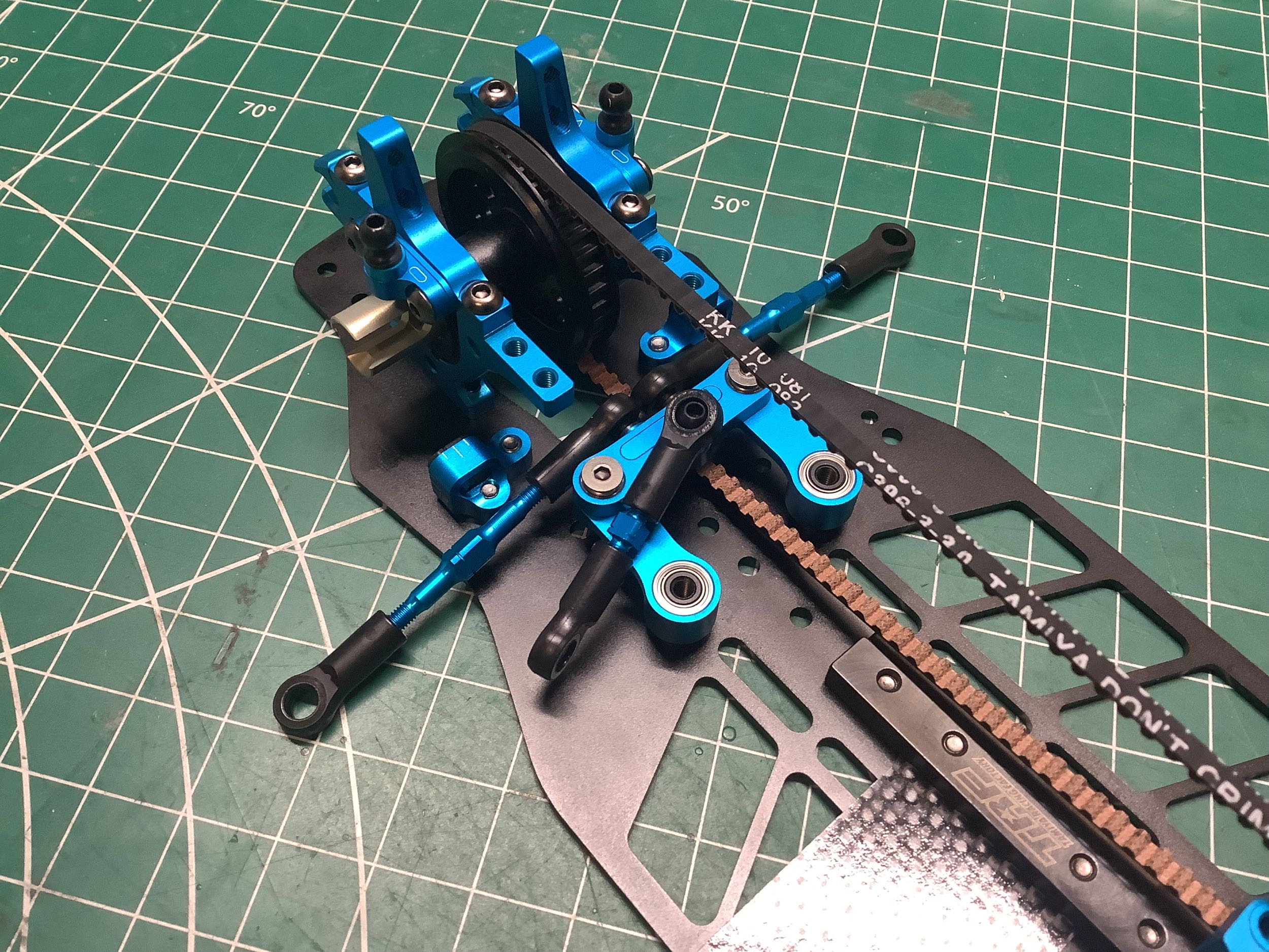
The front pulley is installed using the same type of upper bulkheads as
those used on the rear. With the cams adjusted to tension the
belts, the drivetrain installation is complete. In this image you
can see how much further forward the spur gear is than on previous
chassis.
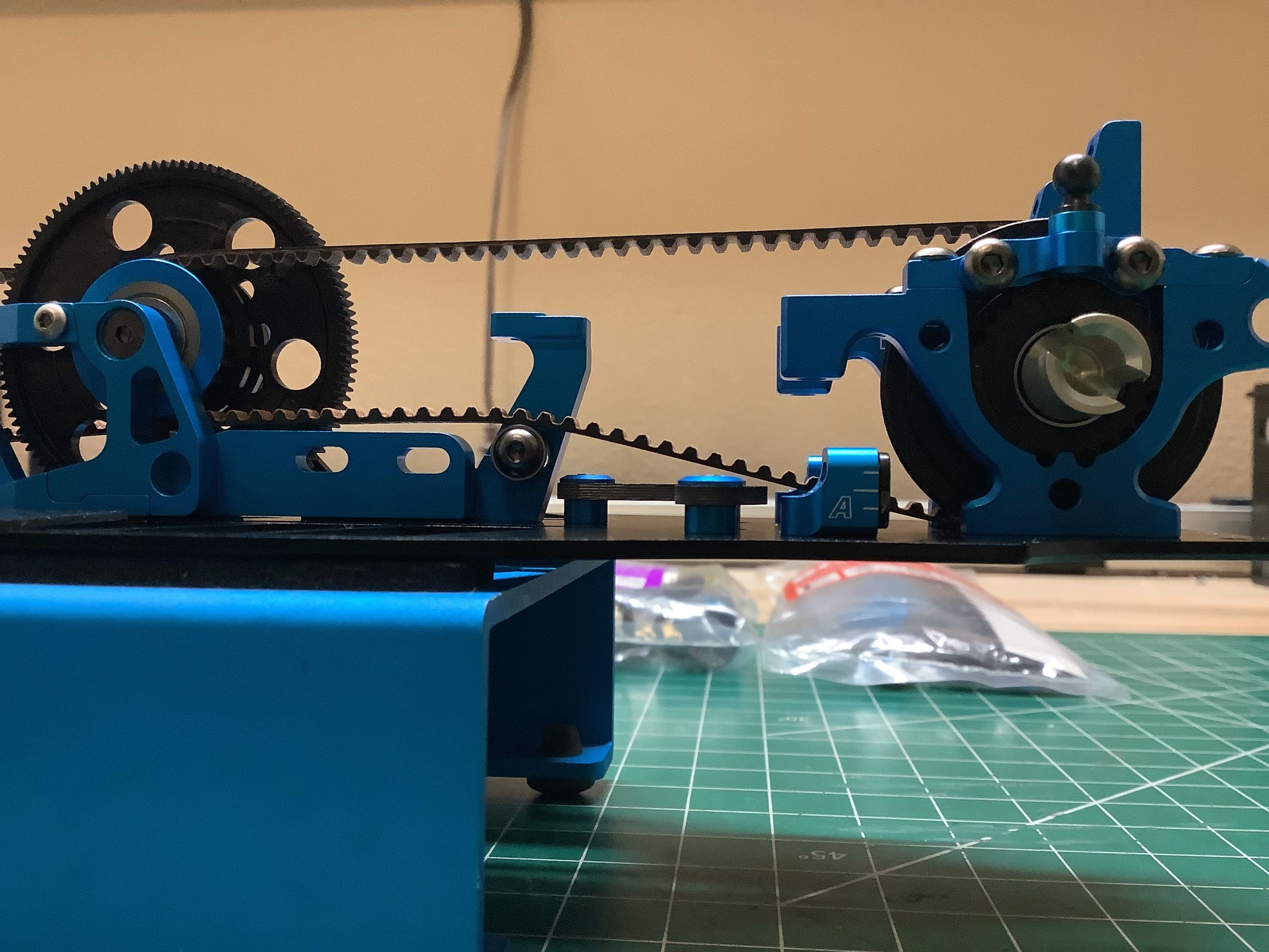
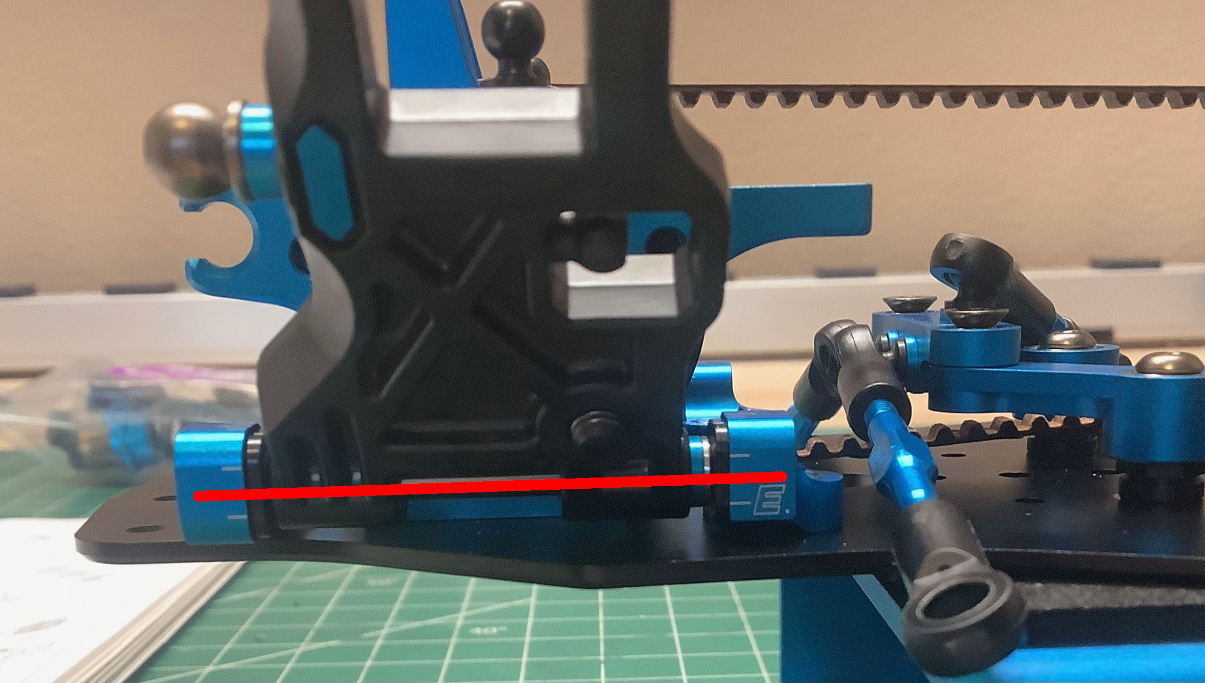
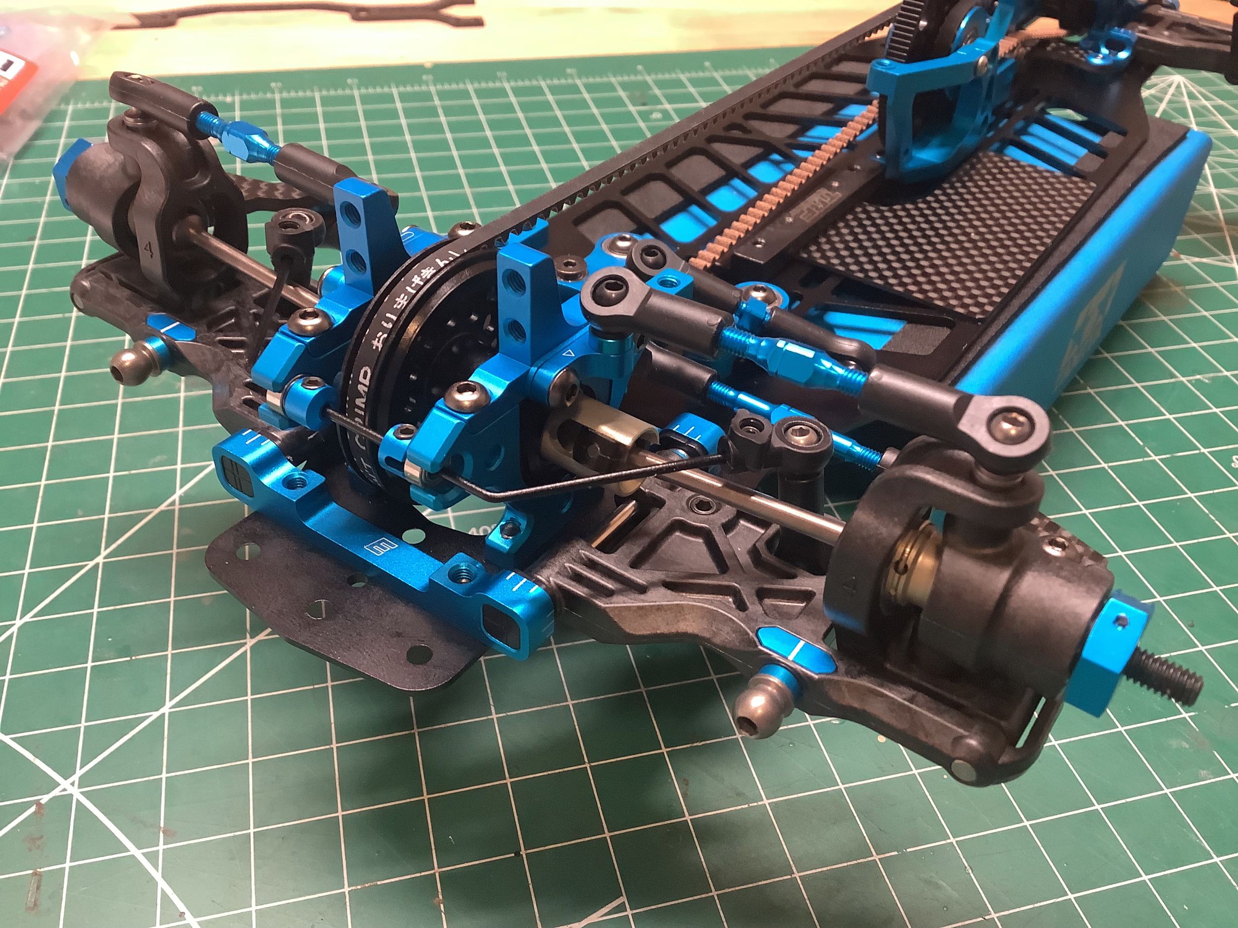
This picture shows the critical new belt routing. Because the
center pulley is now ahead of the motor, the rear belt has to pass by
the motor. Hasn't one of the belts always had to pass by the
motor? Yes, but the front belt was always on the other side on the
spur so it was outboard of the motor pinion. The rear belt, on
the other hand, is on the same side of the chassis as the motor so now
comes very close to the motor and pinion. The ball bearing guide
shown here keeps the rear belt away from the motor mount. We'll
take a closer look at the proximity to the pinion once the motor is
installed.
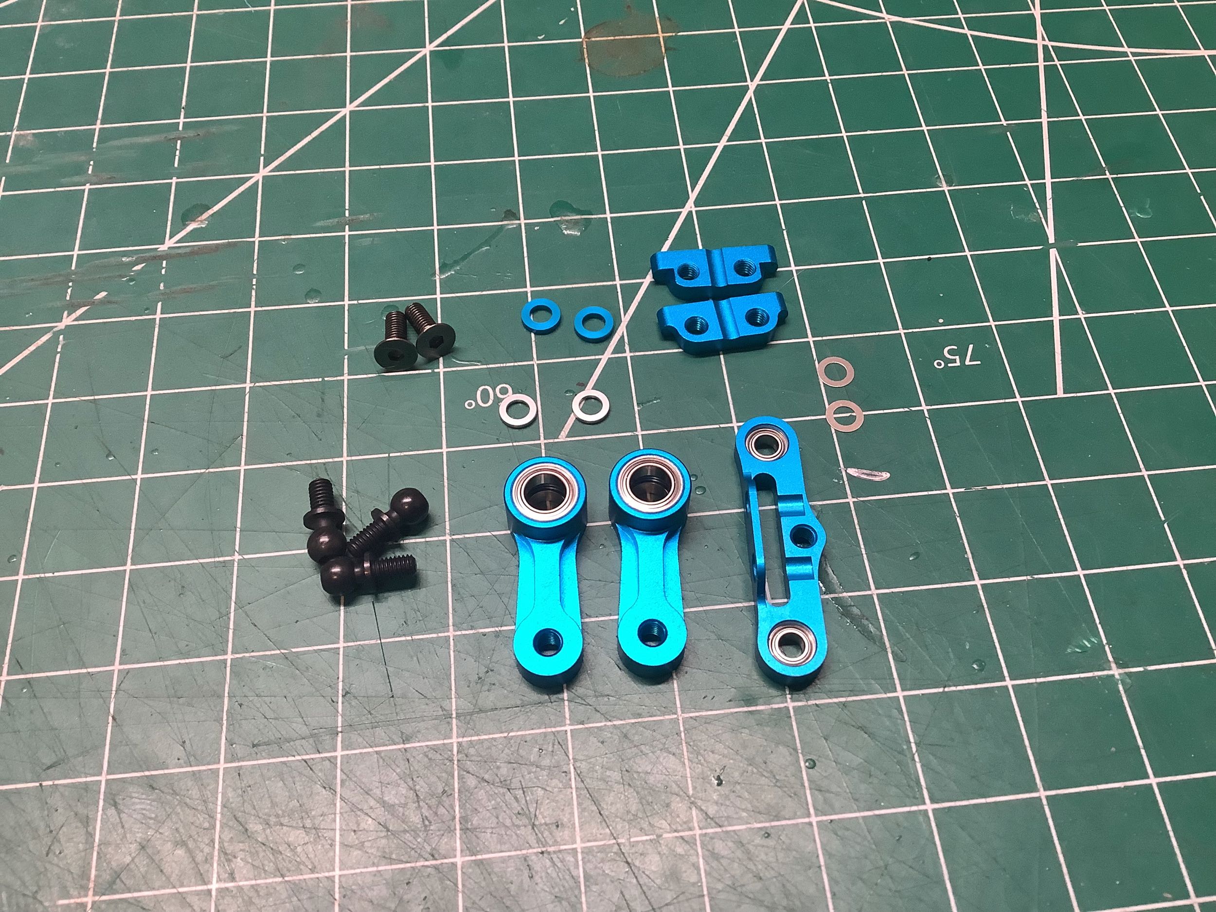
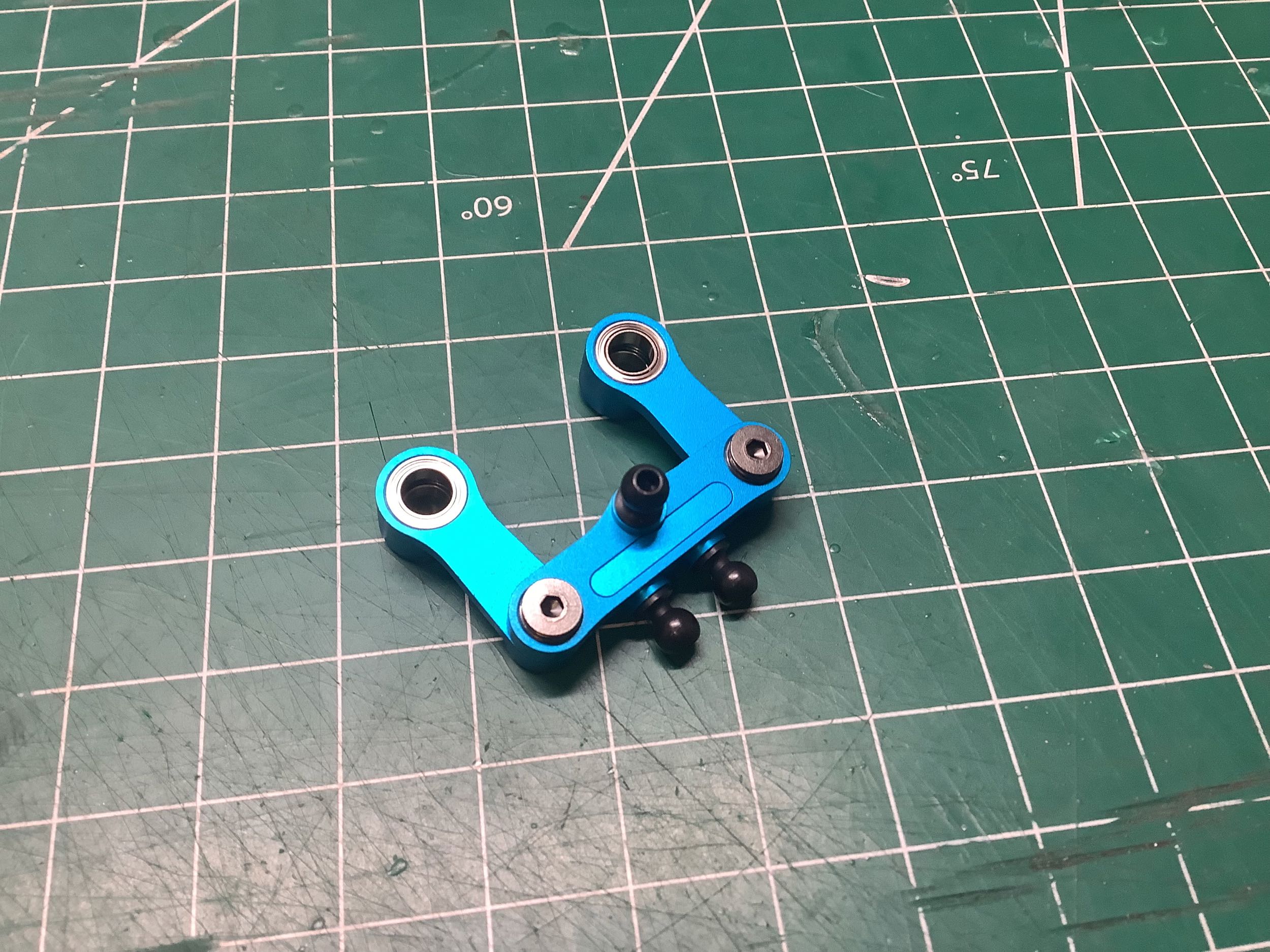
While the steering cranks are unchanged from the TRF 419, the bridge has
been updated to include optional inserts (the manual calls them
"steering pivots") which alter the distance between the ball joints
which connect to the steering links. These parts, shown in the
upper right of the left hand image, have either a 8.0mm or 8.5mm
distance between holes. I can't imagine this makes any relevant
difference to anyone, but I think that about a lot of minor adjustment
options. This was introduced with the original TRF 420.
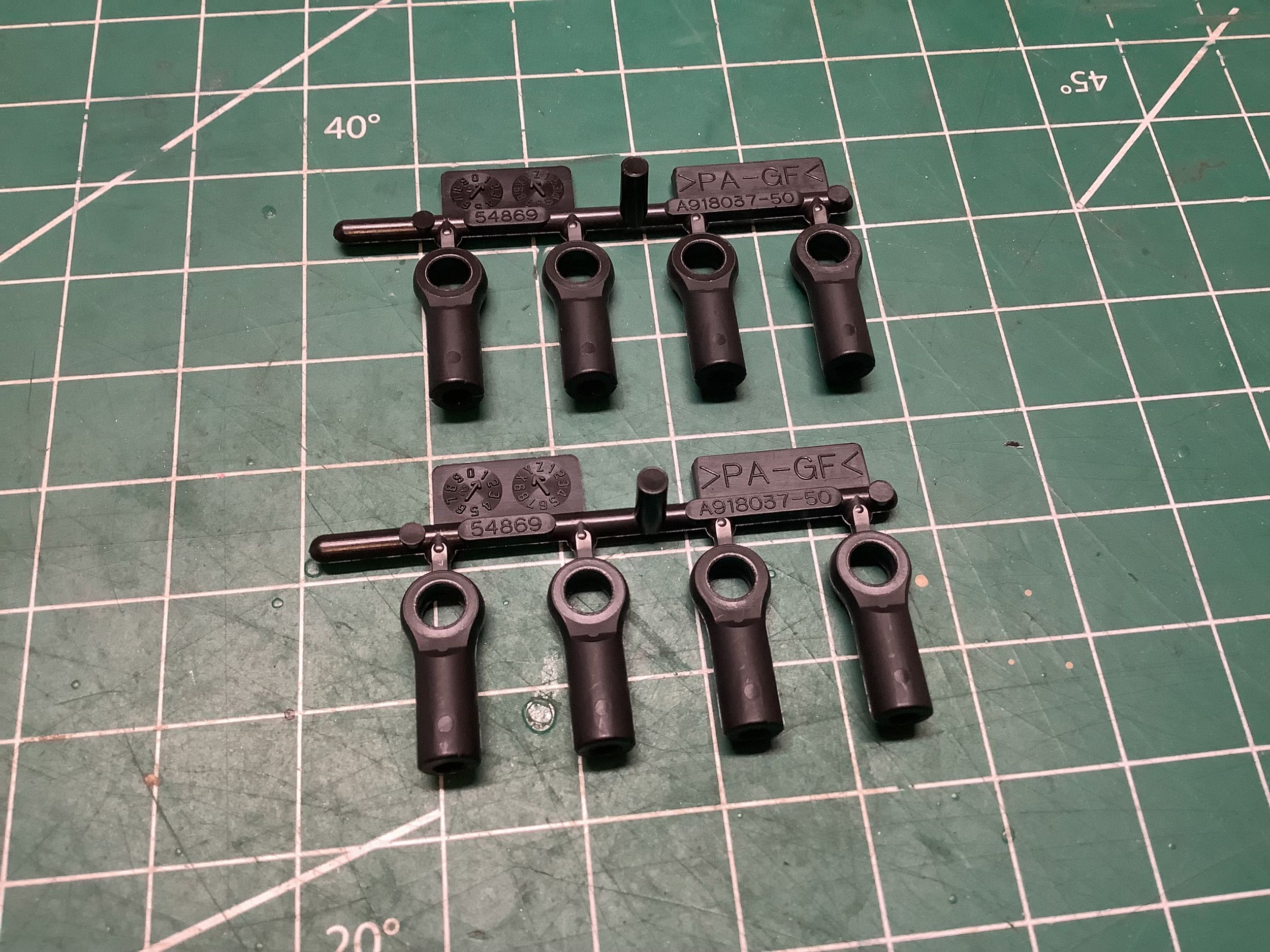
Although the turnbuckles are unchanged from the TRF 419, the ball
connectors (the manual calls them "adjusters") have been changed after
long use all the way back to the TRF 414M. These new parts are now
open on both sides, although a single side has a mark which indicates
the direction from which the ball should be inserted. As far as I
can tell, the only difference on that side is a slight chamfer on the
hole making it easier to pop the ball in. Another less obvious
impact of this change is that the outside of the adjuster no longer has
flats which means you cannot use the Tamiya shock tool to hold the
adjuster while inserting the turnbuckle. I was pretty surprised by
that downgrade in utility.
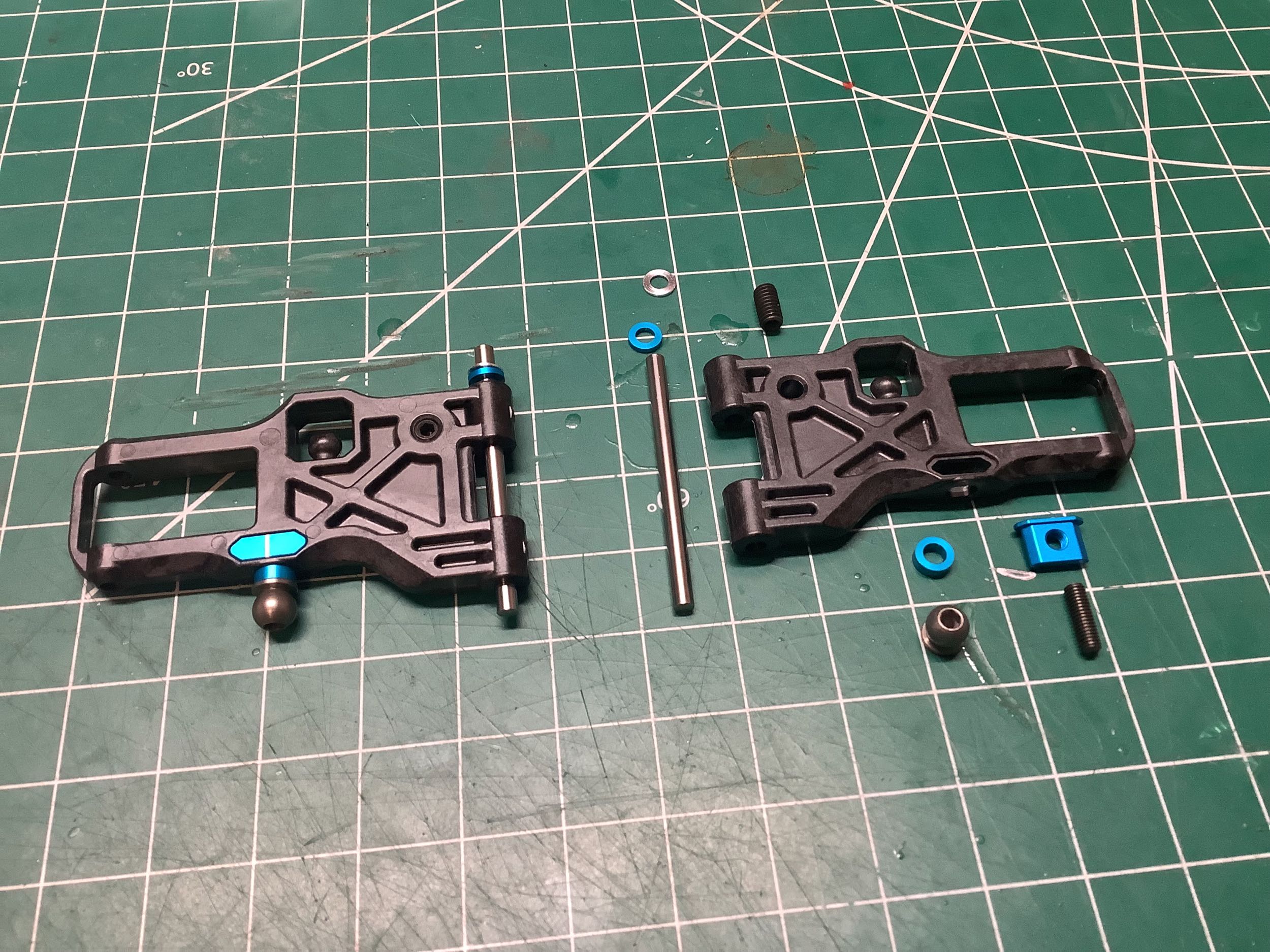
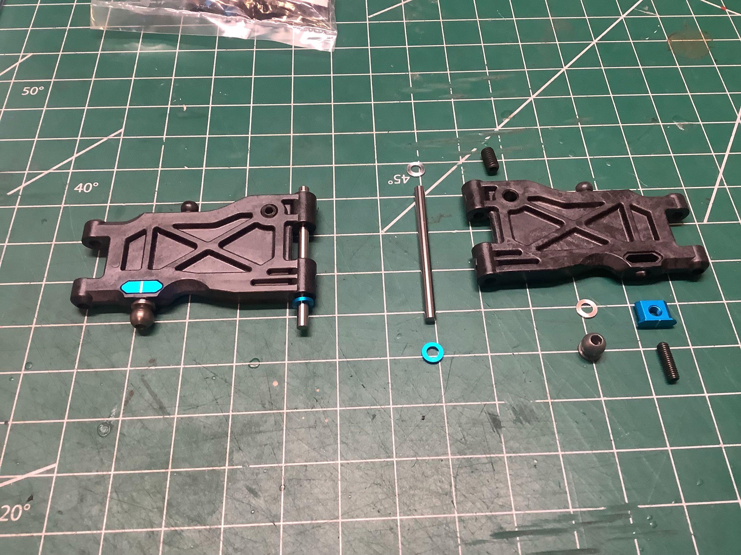
These beefy front suspension arms looks nothing like those from the TRF
419. They were released as part of the TRF 419 Suspension Upgrade
set the same year as the release of the TRF 420 on which they were
standard. Apart from the solid webbing making them very stiff, the
other new feature is the "suspension arm bushings". These
aluminum inserts have the hole for the damper attachment ball, and use
of different inserts changes the position of the hole. This allows
for finer adjustments than would be possible by just having multiple
holes in the arm. The TRF 420X comes only with Bushing B which
centers the hole in the slot. Optional Bushings A and C (the same
part flipped over) move the hole inboard or outboard. The ball
joint which attaches to the damper has also increased to a diameter of
5.8mm.
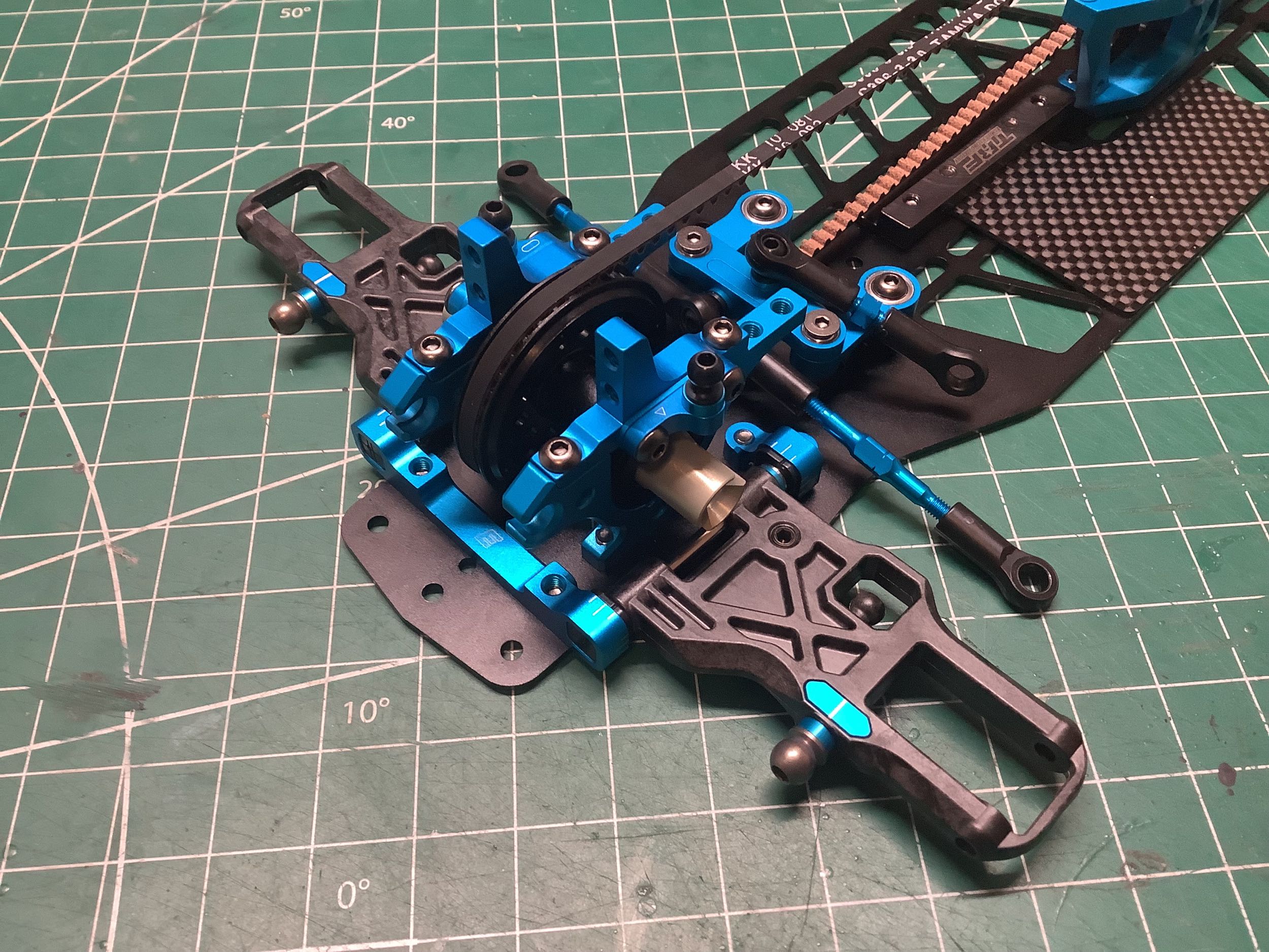
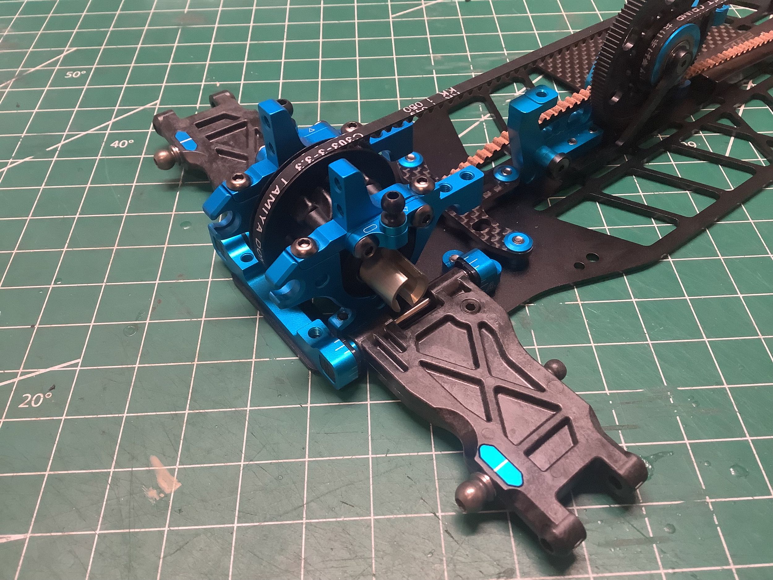
The rear suspension arms have also been greatly reinforced as shown and
use the same Suspension Arm Bushing B as the front. On the right
you can see how they look installed along with the rear suspension mount
(Type E).
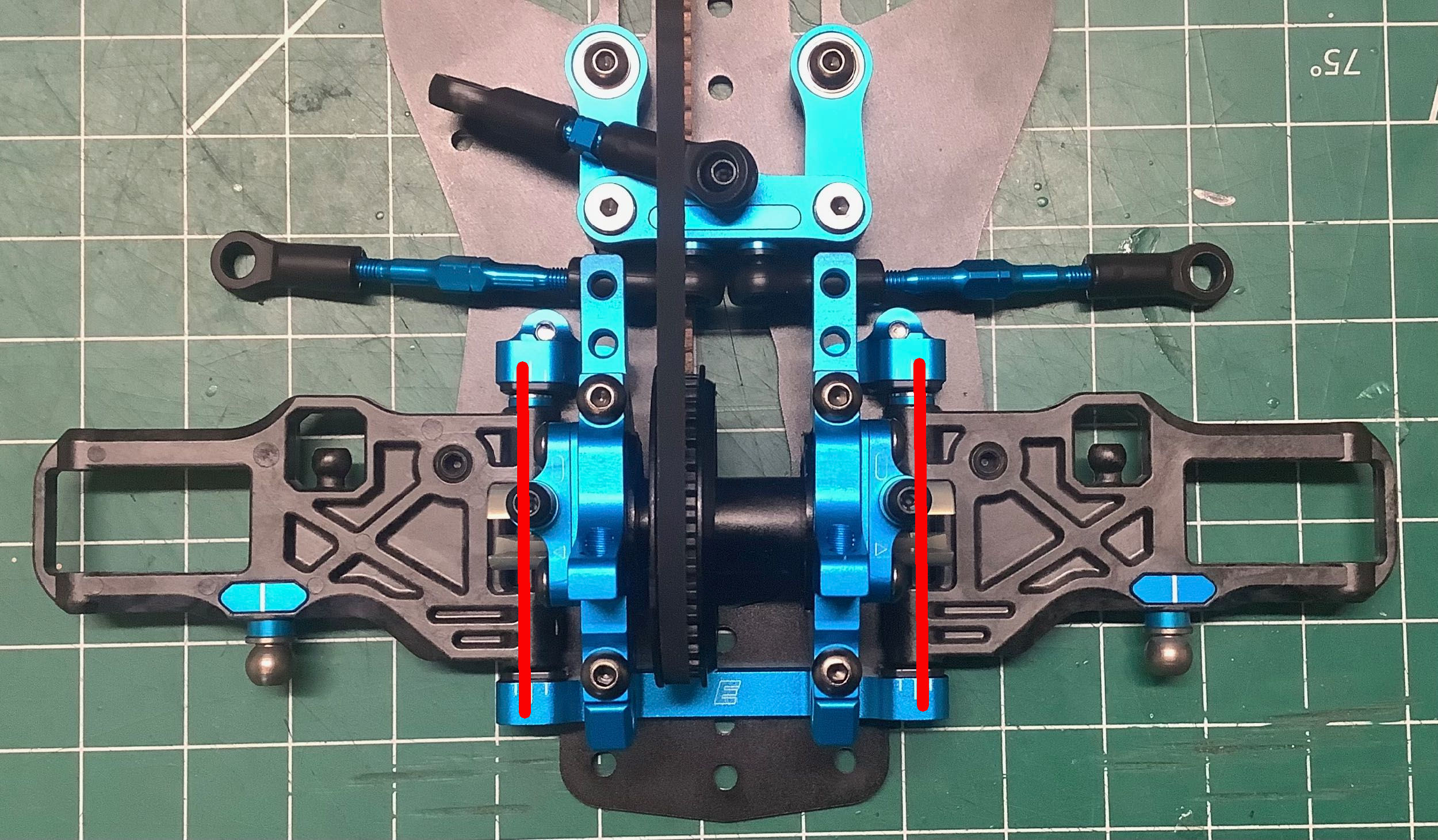
When viewed from directly above you can see the new stronger suspension
arms and the white line on the bushings which identifies them as Type B
with the hole centered. You can also see the front sweep angle rear toe
angle of the arms indicated in red. The front uses both suspension
mounts E and inserts N2 with the holes shifted outboard. The use
of symmetric mounts and inserts results in no front sweep angle and
using inserts with the hinge pin holes shifted outboard slightly
increases the track width. The rear uses forward suspension mounts
A and rear suspension mount E and inserts N2 with the holes shifted
inboard. The use of asymmetric mounts with symmetric inserts
results in a rear toe angle of 2°. Adjustments in 0.5° increments
can be made by changing the rear inserts only.
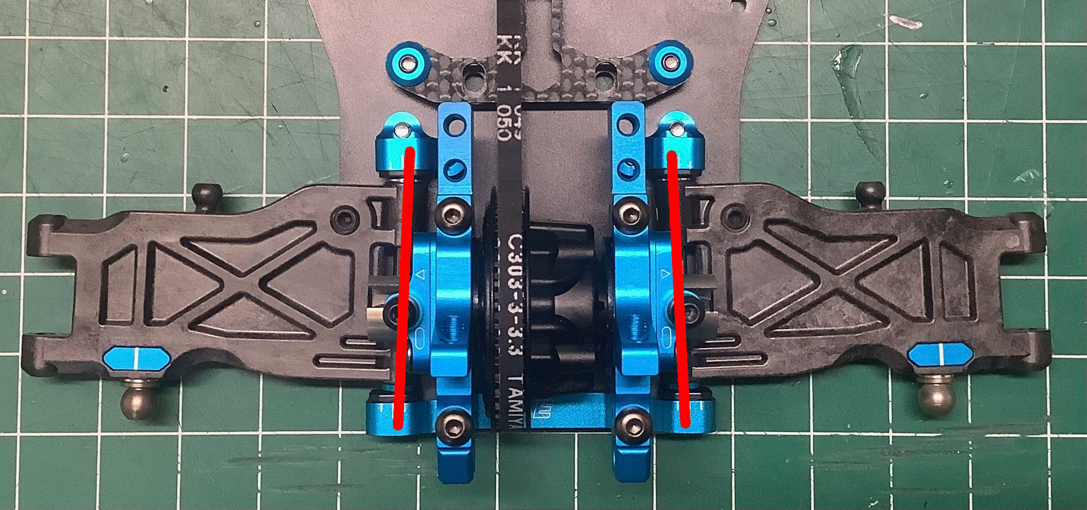
These pictures of the suspension hinge pins shown from the side
illustrate the skid angle (or "dive angle" in the front and "squat
angle" in the rear). Since the N2 inserts are centered vertically
there is no skid angle, but using asymmetric inserts would alter that
angle. Using symmetric inserts with higher or lower holes would
alter the roll center. Apart from changing the inserts, these
options can also be adjusted by adding shims under the suspensions
mounts either differentially or in matched sets.
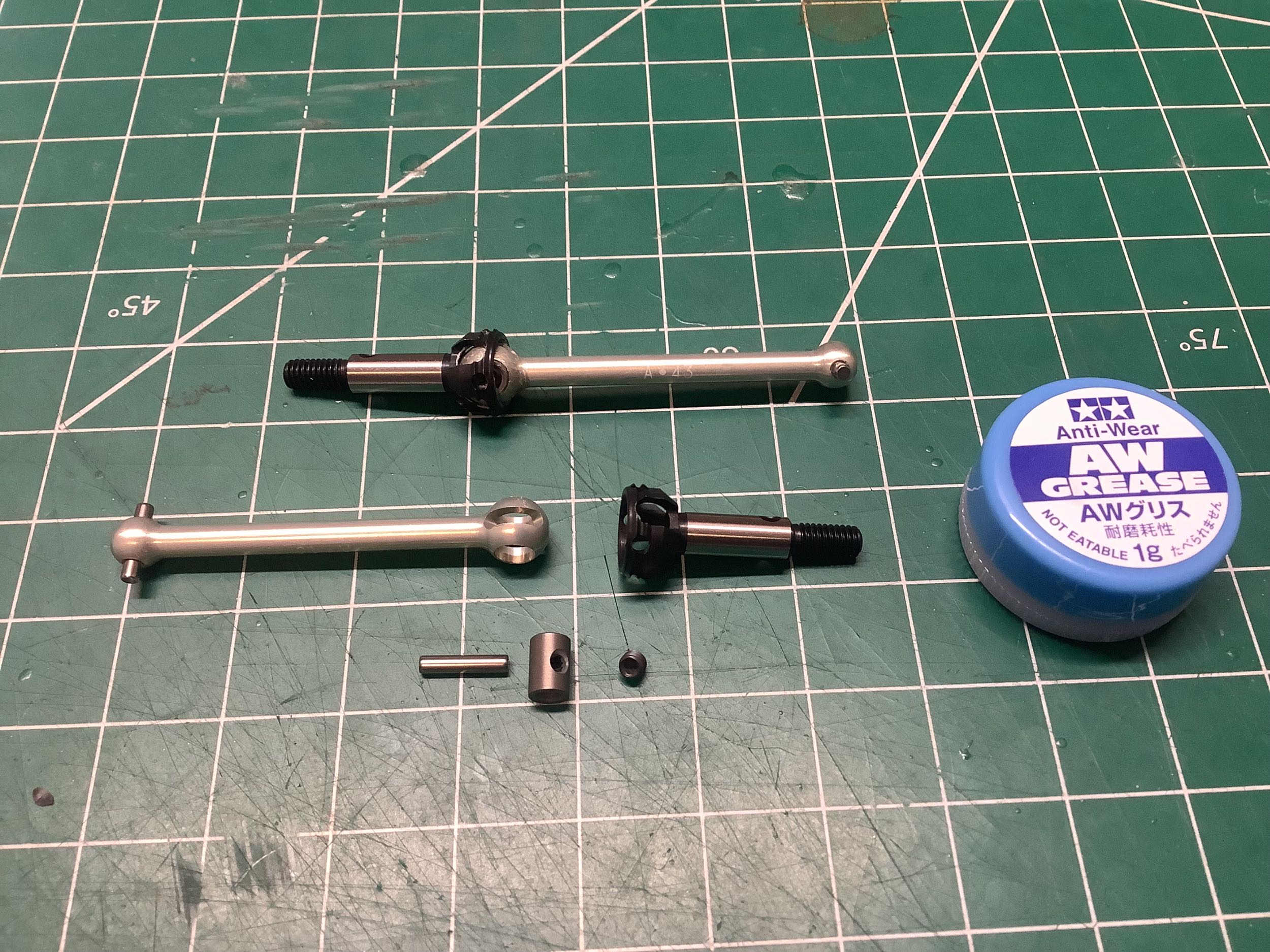
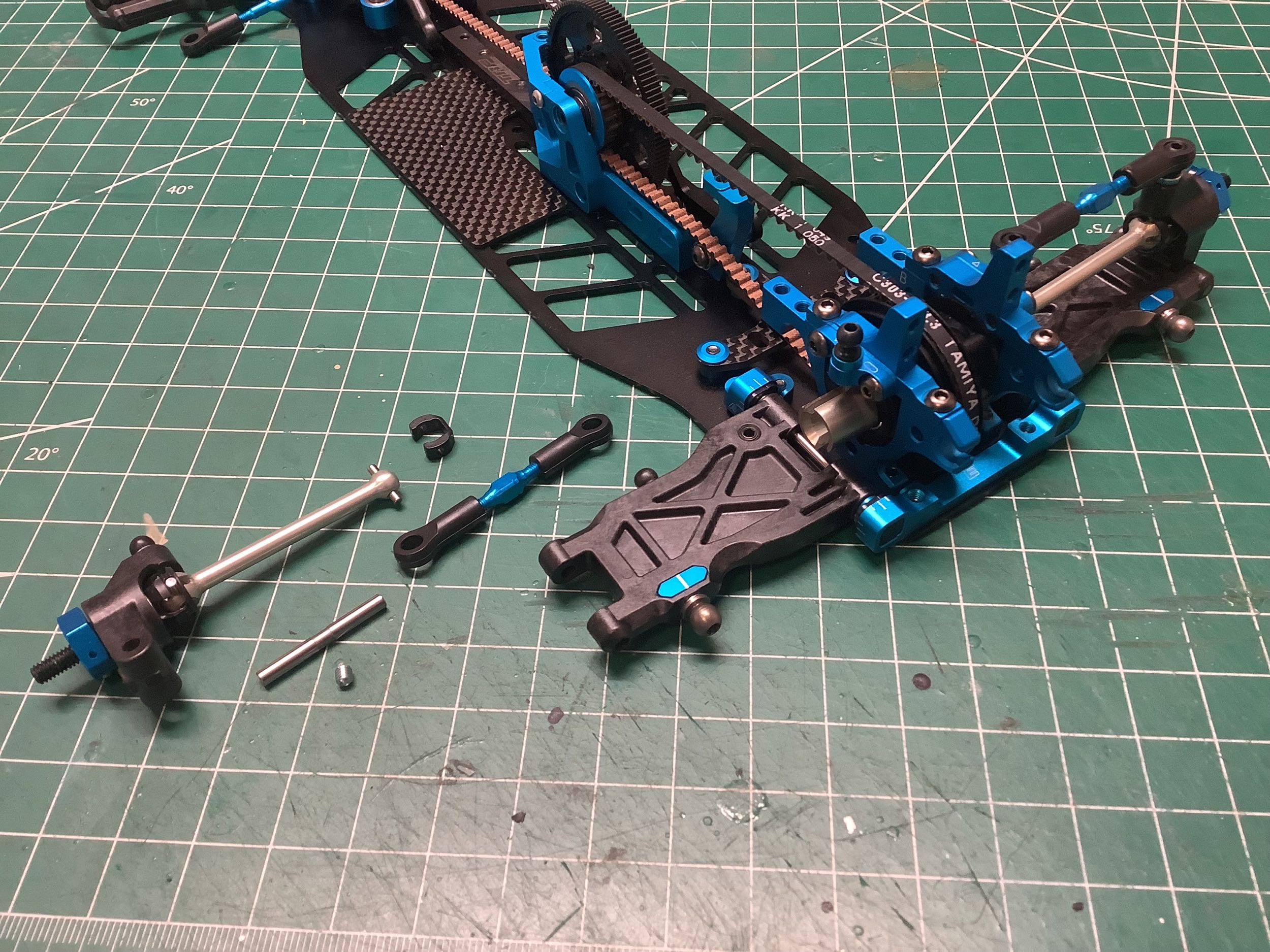
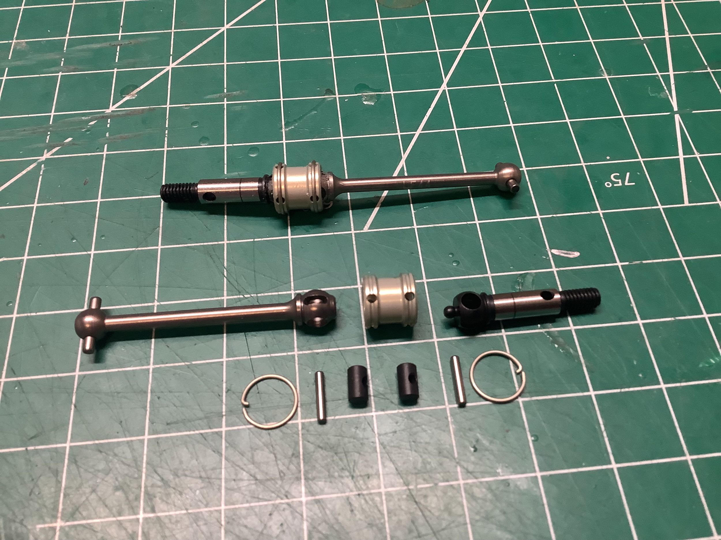
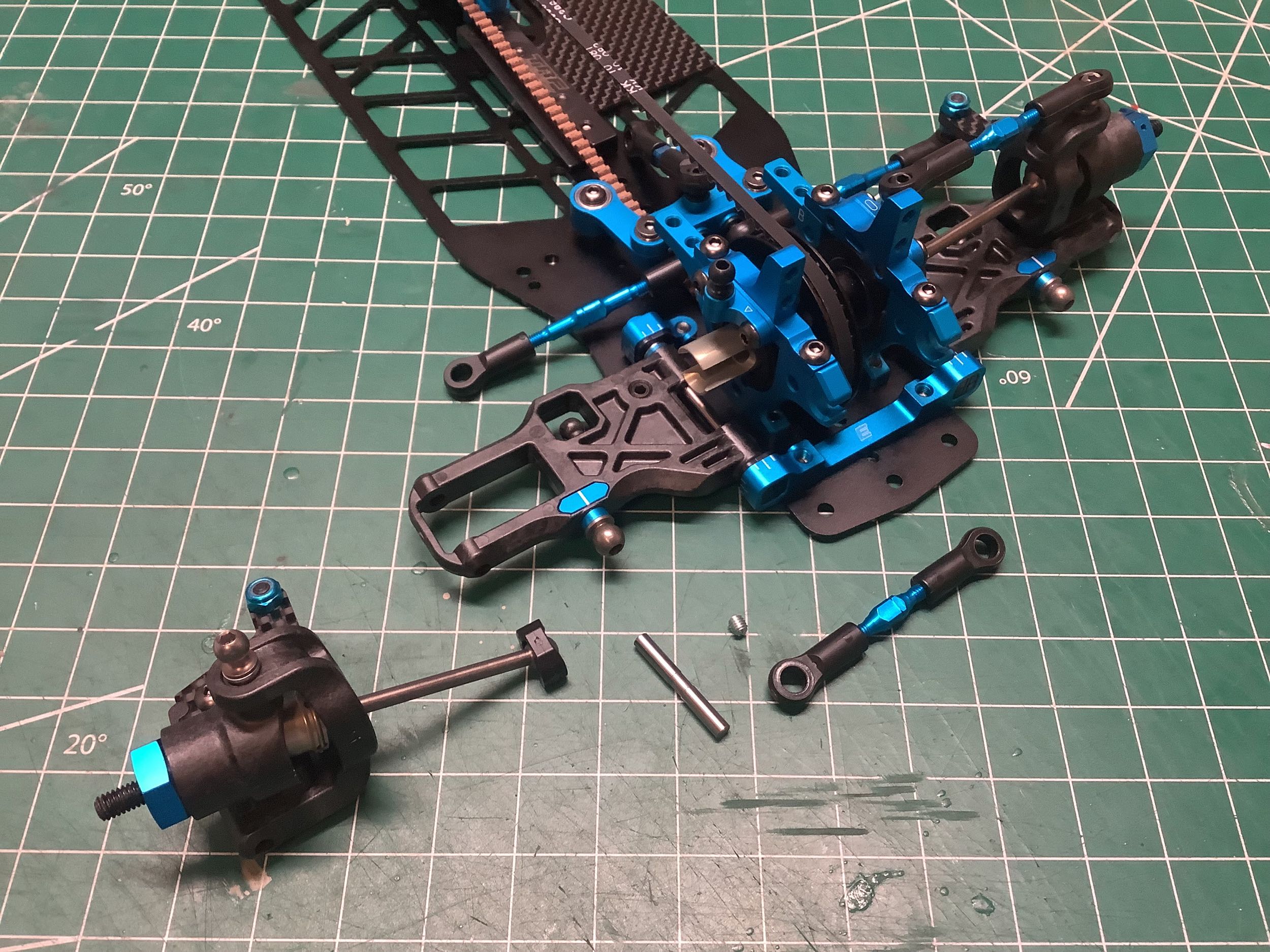
These CVD style axles are a lot different than what was used on the TRF
419. While the dogbone end is still aluminum, the blue anodize has
gone away and the length has reduced from 44mm to 43mm. The steel
cup end has been heavily pocketed for weight, and the pin retention has
reverted to a set screw instead of an axle ring.
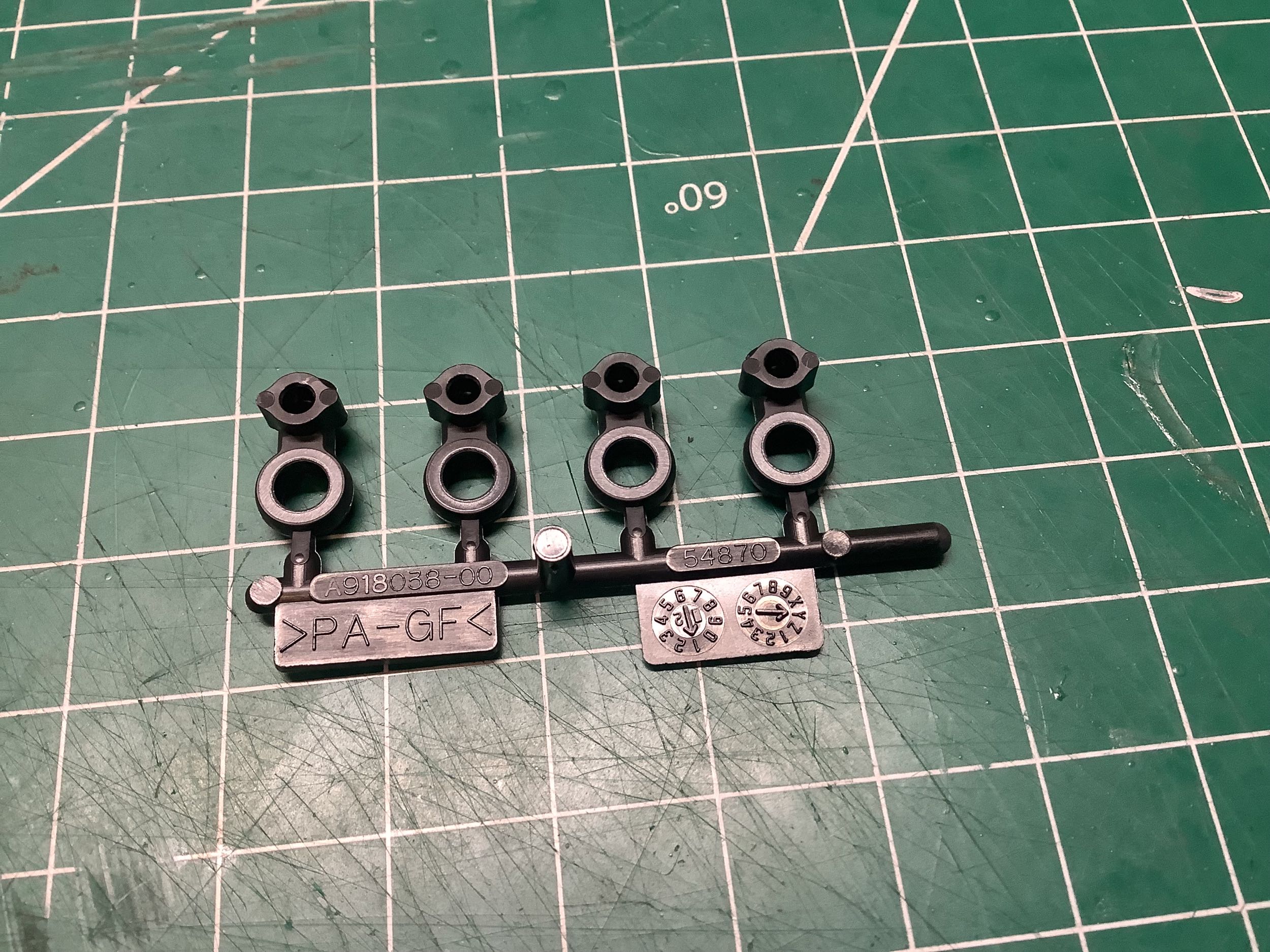
The only noticeable difference in the uprights between these new
versions and those from the TRF 419 is that the holes for the hinge pins
have increased from 2.6mm to 3.0mm in diameter. Obviously the
hinge pins themselves have also gotten bigger, but the retention flat in
the middle has also become a groove that goes the all the way
around. This makes it much easier to install the retention set
screw because nothing needs to be aligned. The uprights are
identical left and right meaning there is no built-in toe angle.
The new adjusters are also on display in the camber links.
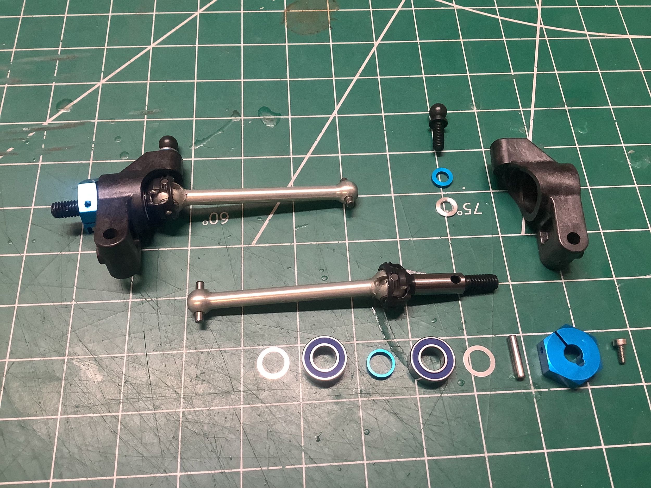
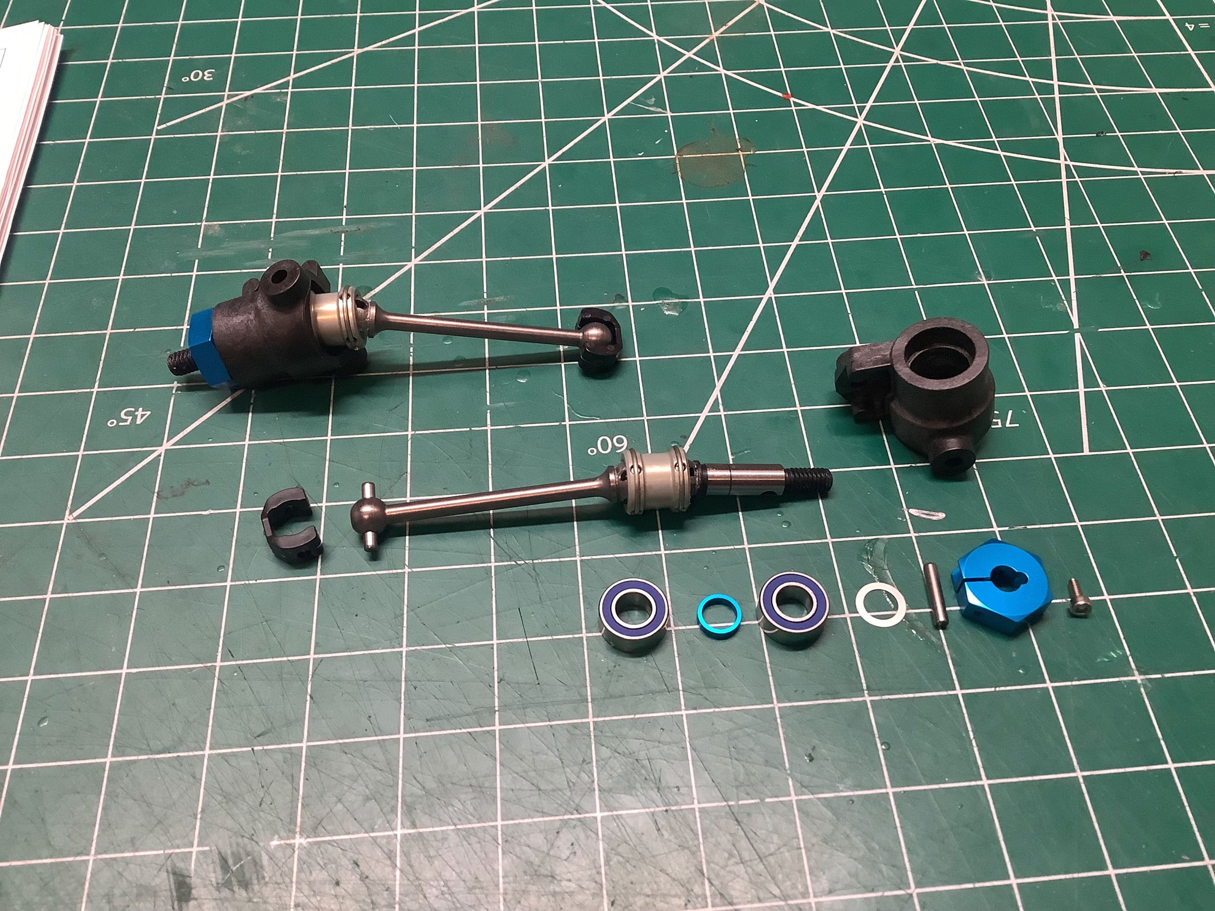
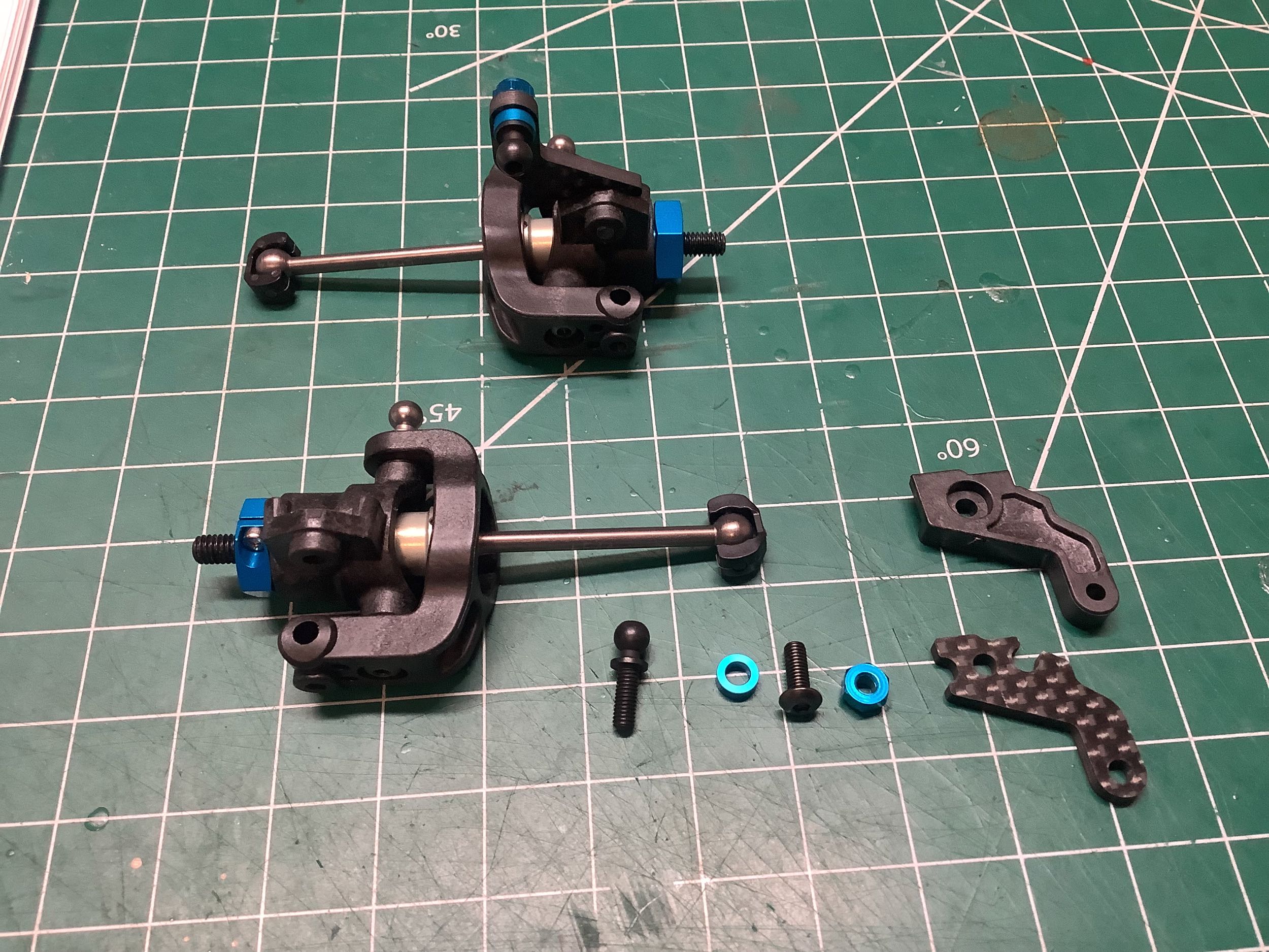
The front double cardan axles have also been updated. The center
joint pipe has changed from steel to aluminum and the dogbone axle has
lost it's black oxide finish. The steering knuckle has also
changed considerably. More on that in a bit.
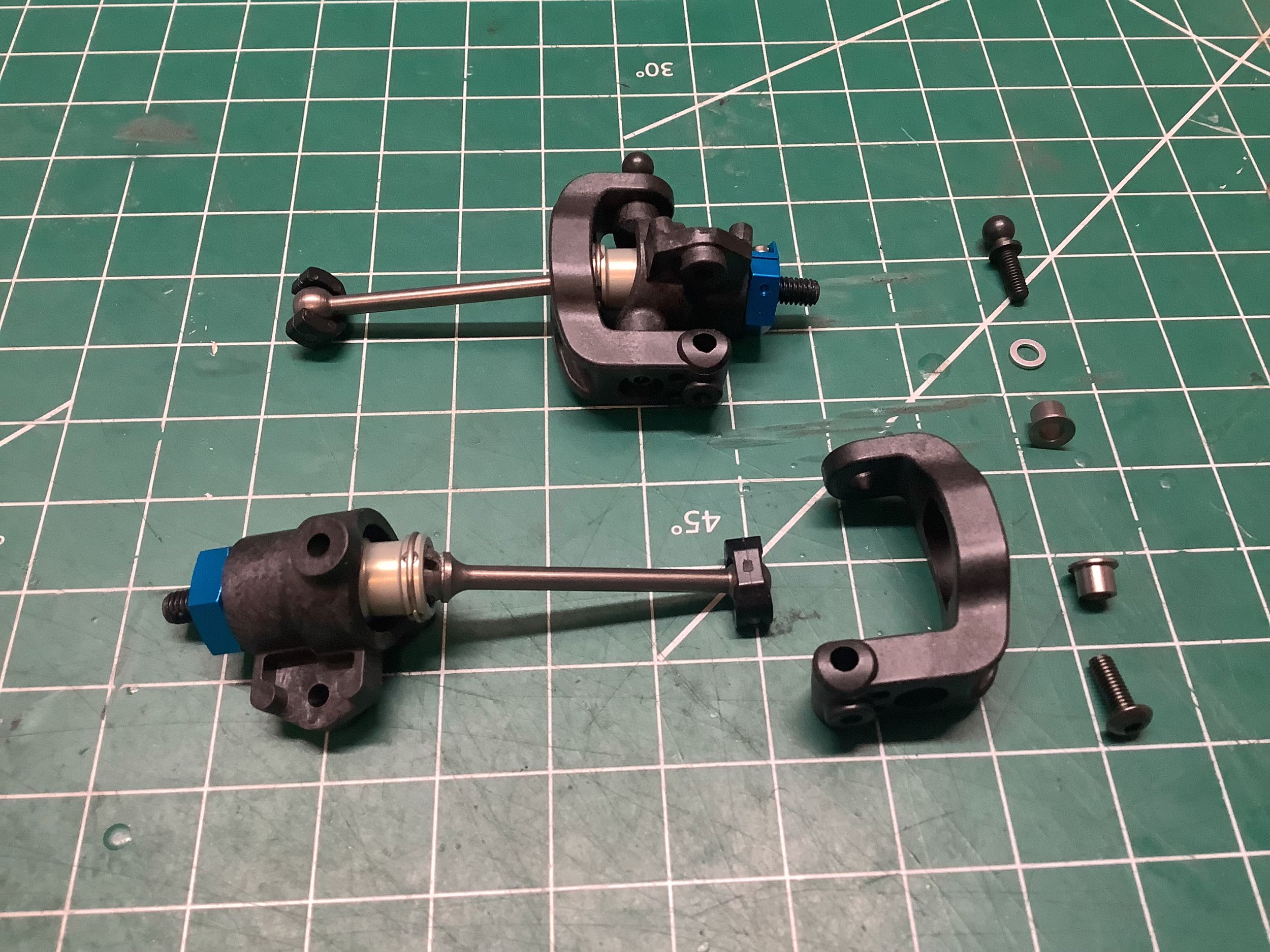
The C-hubs have a nice big square opening to make room for the double
cardan pipe, and the upper and lower pivot bushings are now both the
same size which makes assembly much less prone to error. There is a
4° caster angle built into the hubs. A completely new feature is
that the steering arm is now a separate part instead of being built into
the knuckle. The carbon fiber part is used by default, but an
optional plastic part is also available (both shown at far right).
The carbon part has is slightly longer in the longitudinal direction so
while the Ackerman is the same, the carbon part produces more steering
angle for a given servo input. I decided to use the carbon parts.
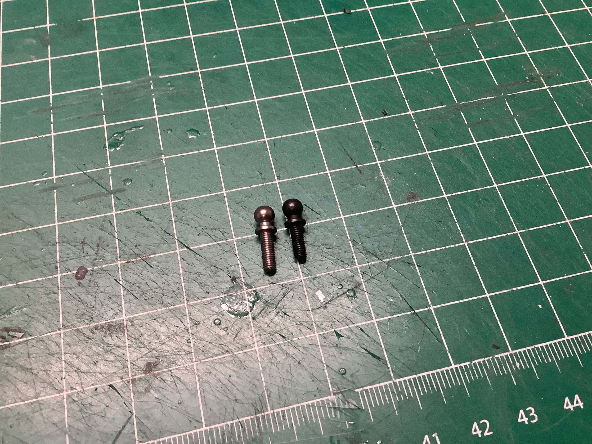
Did you notice the difference between those two ball studs? I
didn't. One of them is 8mm long and the other is 9mm long.
Tamiya made them different colors to make it more obvious, but I still
didn't notice until I'd already installed them wrong. The longer
one is the upper hub pivot and camber link attachment. The shorter
one is the steering link attachment. On the right you can see the
installation of the front hubs onto the chassis using the larger 3mm
hinge pins again.
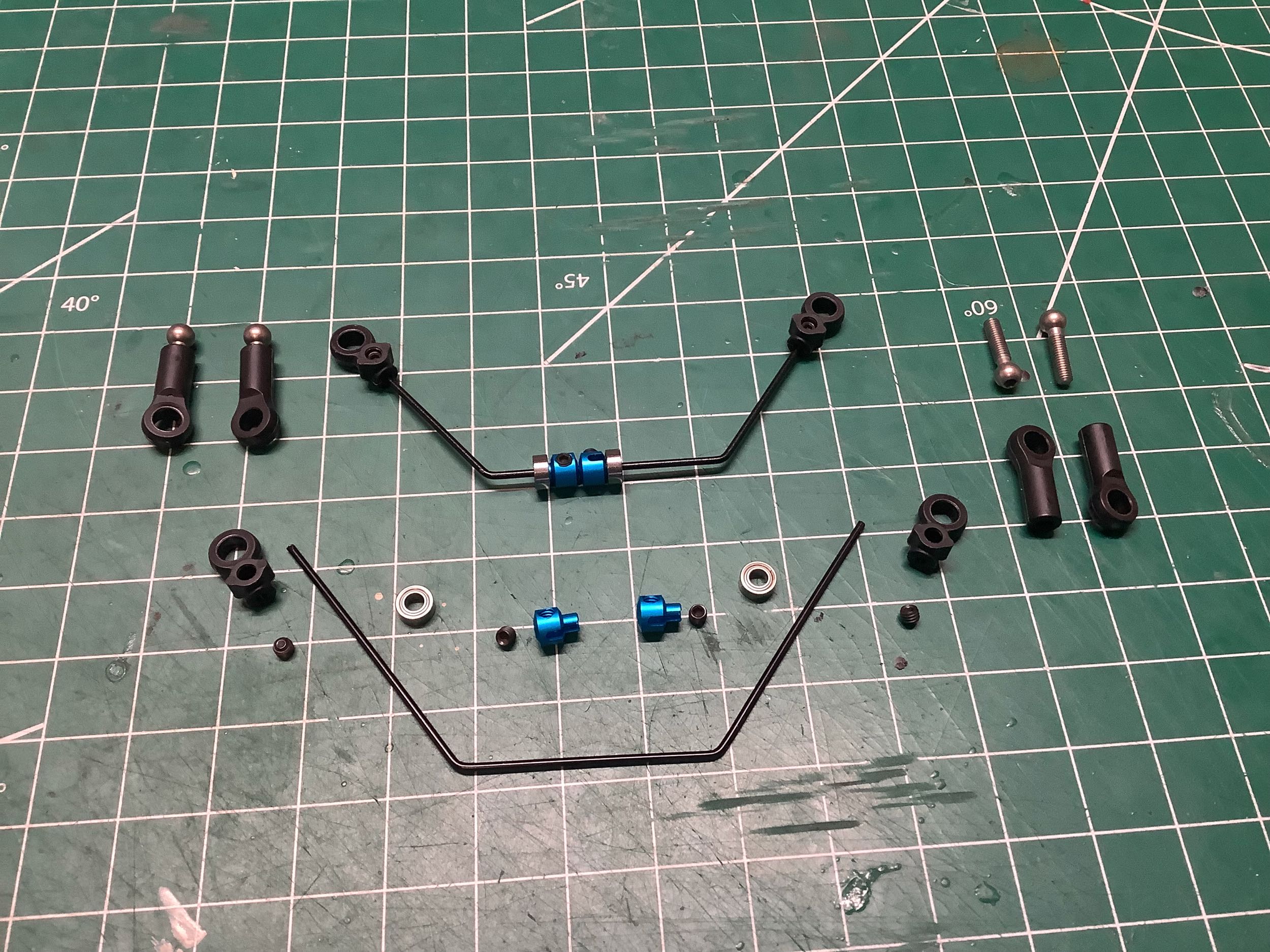
This completely new way of mounting the sway bars was introduced with
the TRF 419XR. For many years the sway bars had been guided on the
chassis with nothing more than a couple of loose plastic slots and set
screws which resulted in most of one side's motion being lost in free
play before it was transferred to the other side. This new system
uses ball bearings guided on the bulkheads to support the sway bars
instead. This results in vastly more effective sway bars.
The plastic ends of the sway bars are also new. The set screw
which retains them has moved from an aluminum collar into the plastic
end itself which I suppose is cheaper and lighter. Uglier too
though. Remember those 8mm and 9mm ball studs I talked about
earlier? These are 10mm just to shake things up a bit.
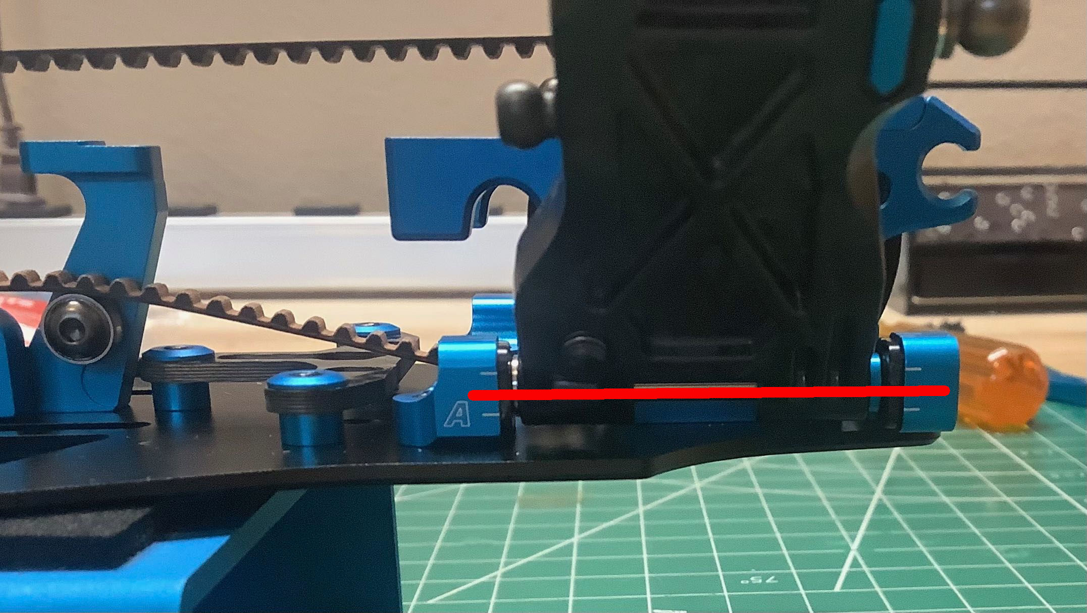
Here you can see how the sway bar bearings are supported by the
bulkheads. This makes the bulkheads much more complex to machine,
but it does wonders for the utility of the sway bars. The bearings
must be slid outboard into the bulkheads to install them, and then the
blue aluminum collars lock them in place with set screws. Compared
to the TRF 420, the 420X changed the geometry of the bearing slots in
the bulkheads. The 420 has the slots open toward the top which
made vertical forces on the sway bars want to pop out the
bearings. Now the slots are open toward the front and back
instead. Strictly speaking they wouldn't have to be slotted at
all, but doing so means a less tight tolerance is needed on the
counterbore to grip the bearing with no play.
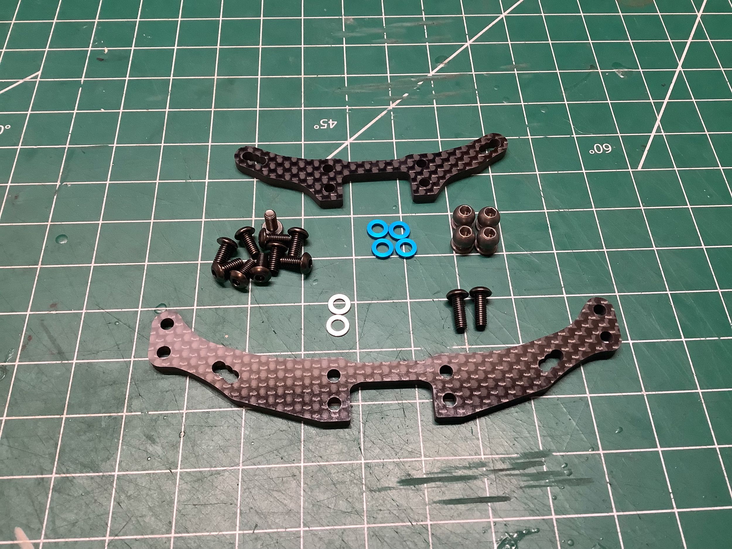
These shock towers are designed for the super short dampers. They
no longer use countersunk screws which makes them slightly stronger
since less material is removed by the hole. They have less
material connecting the right and left halves than TRF 419 making them
somewhat more flexible.
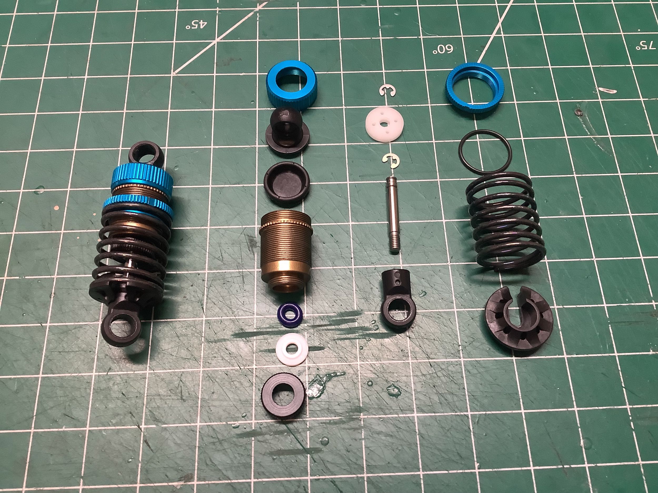
The super short big bore dampers were introduced with the TRF 419X, but
the TRF 420 debuted the new V-parts (shown at left). The most
obvious difference is the availability of head ends that accommodate
5.8mm balls instead of 5mm balls. The new parts also have
the advantage of being reinforced for more strength, and parts for the
old ball sizes are also included for backwards compatibility.
Short and long rod ends are also included in both diameters.
Finally, spring perches are included in two diameters to accommodate
both big bore and standard shocks. It's a bit disappointing that
we lost the nice aluminum spring perches from the TRF 419. When
building these shocks, the manual calls for a 1mm hole to be drilled
into the head end cap. This relieves pressure behind the bladder
and eliminates rebound.
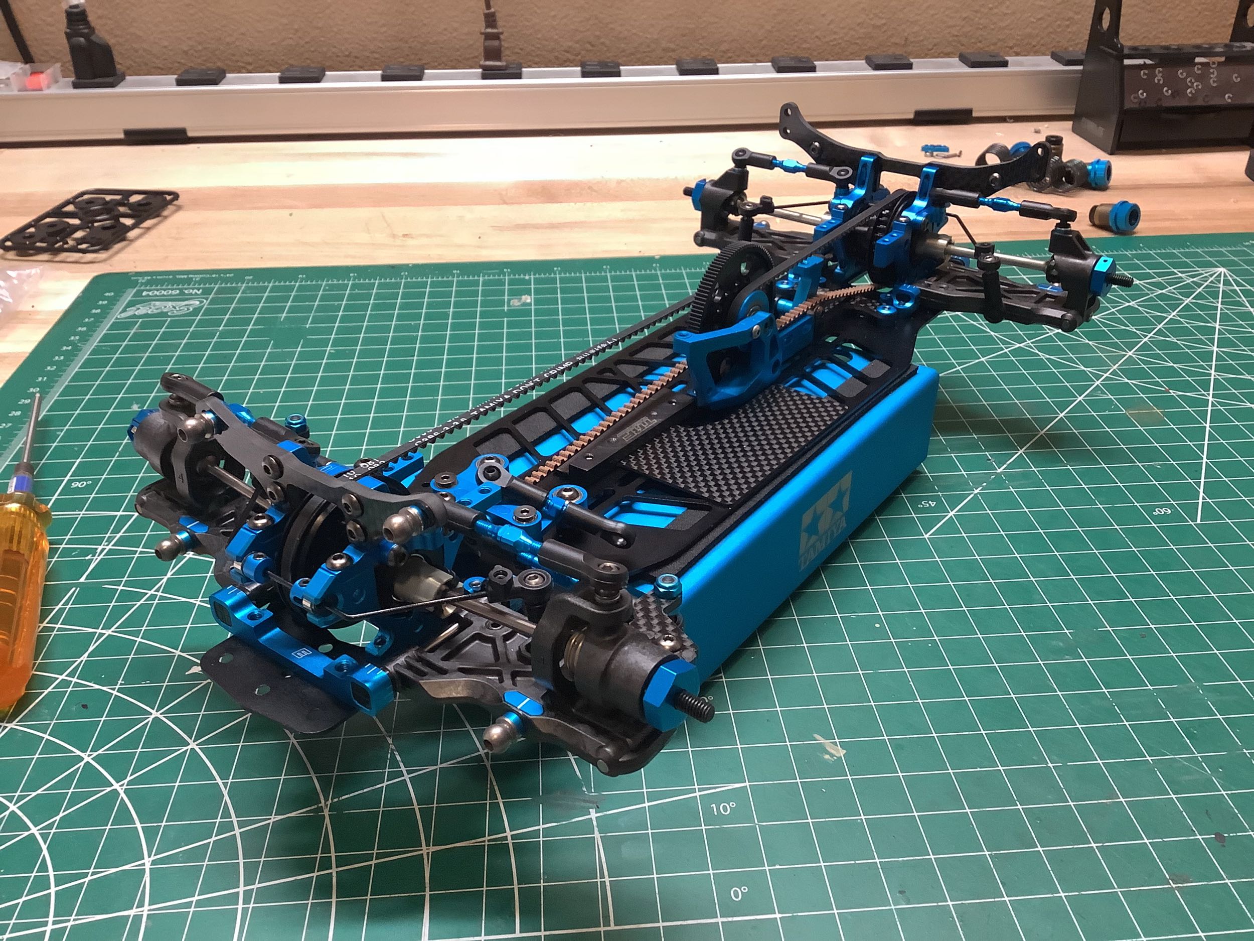
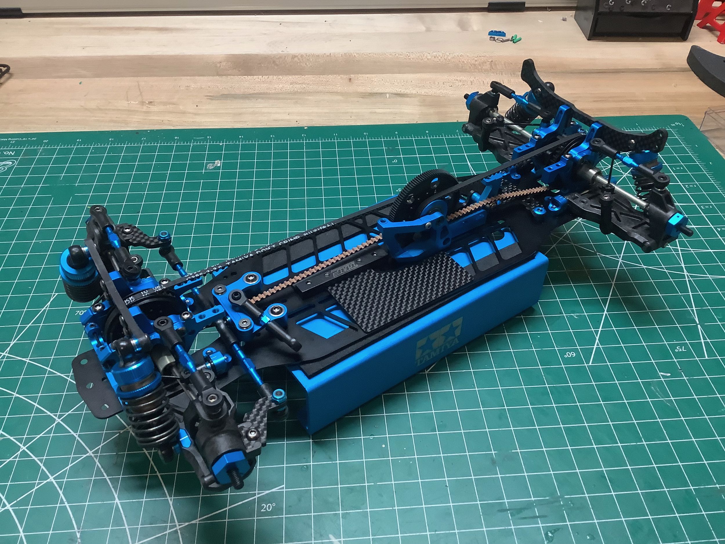
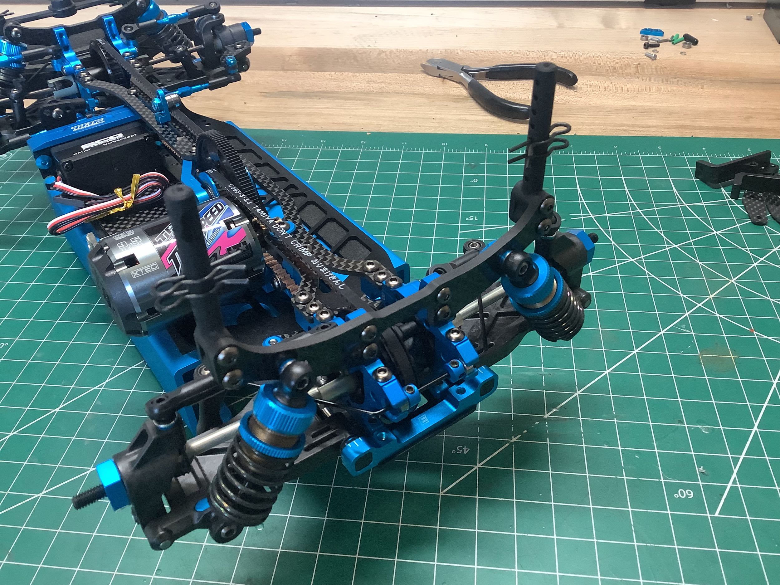
Installation of the shocks completes the suspension assemblies and the
rolling chassis. With the aluminum lower chassis plate, this
version is noticeably different than my prior builds.
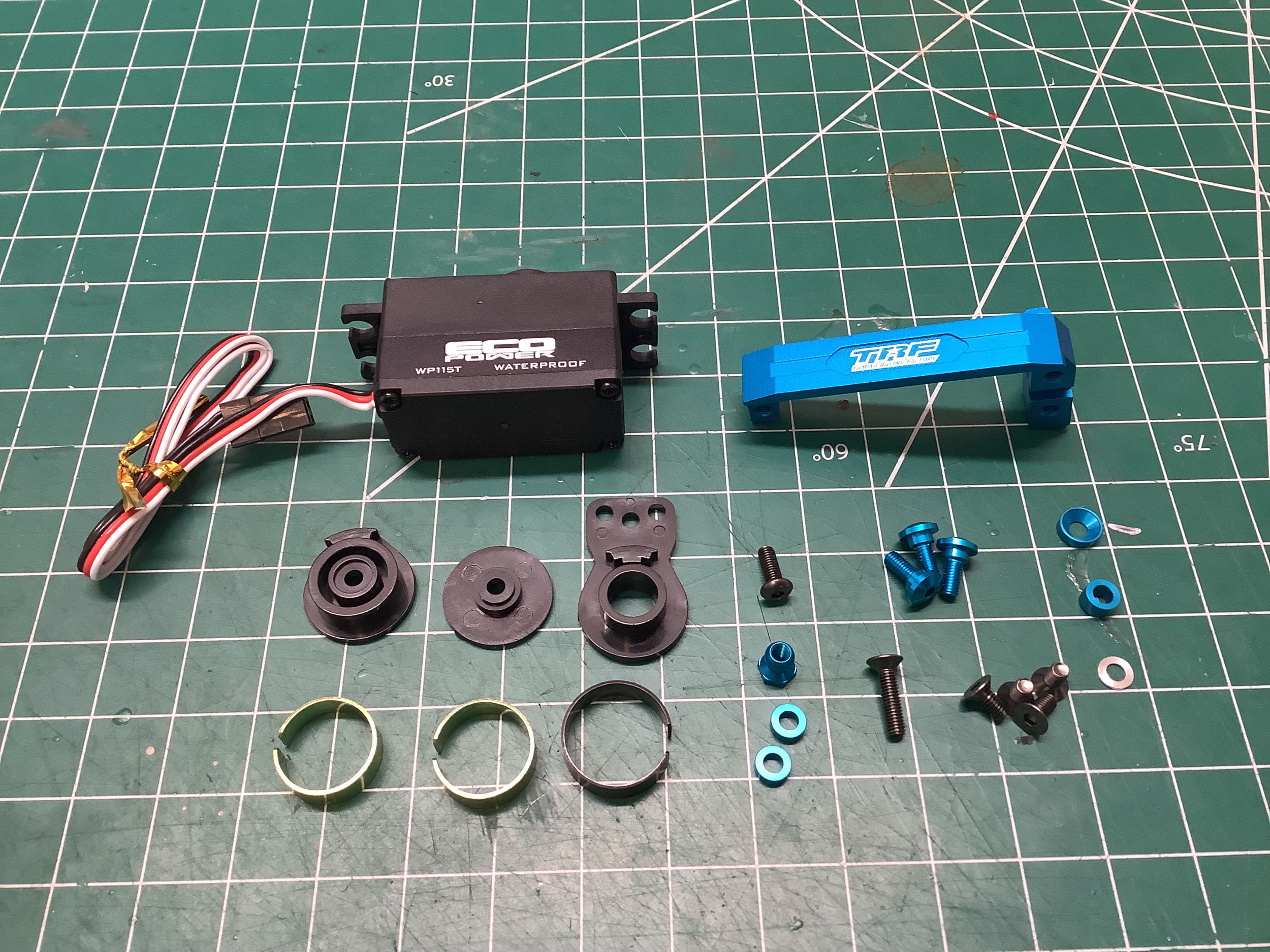
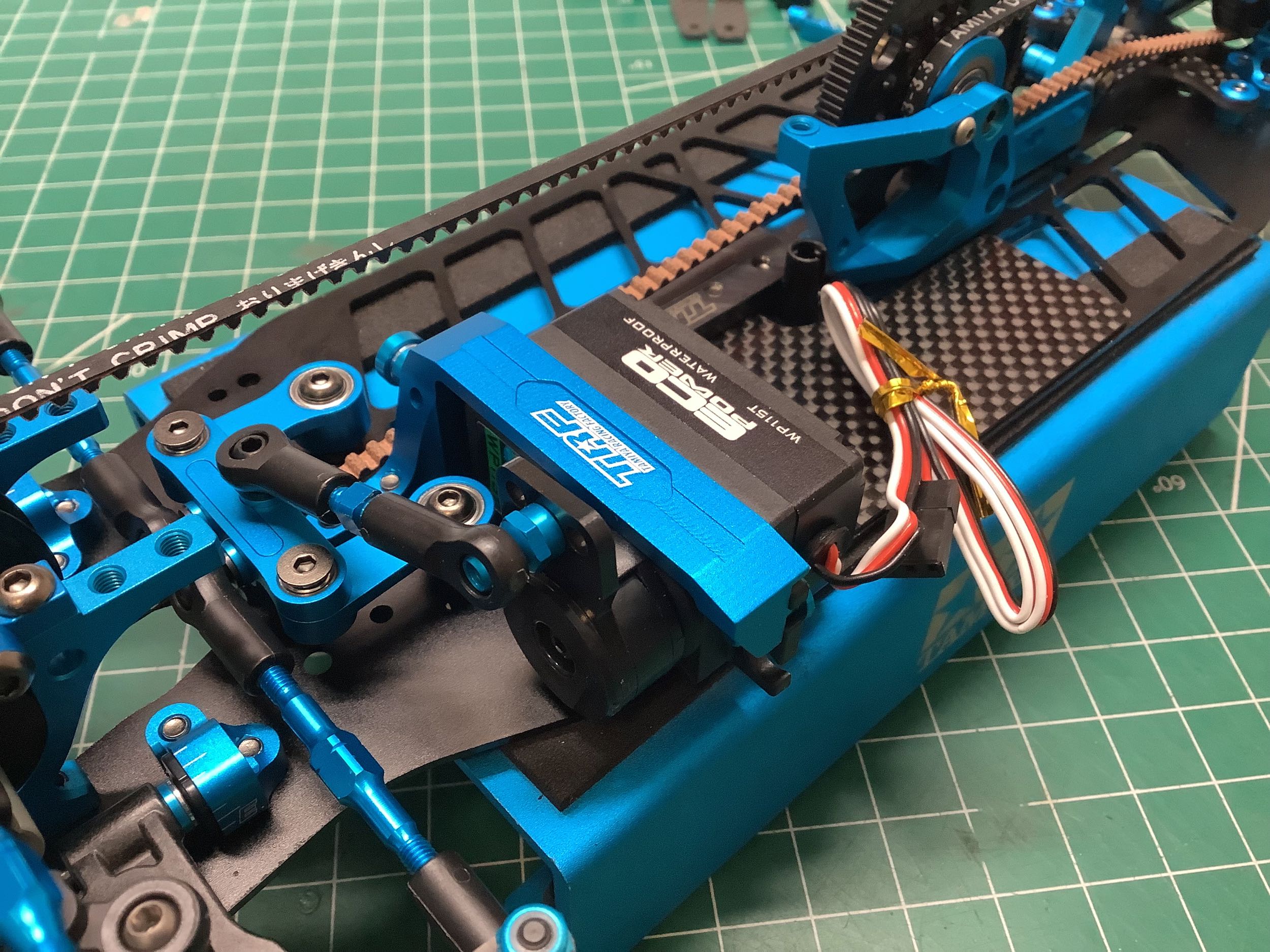
The cantilevered servo mount is the same idea as the TRF 419 but uses an
updated part with a nice TRF logo on it. The bracket is now
located forward of the servo mounting tabs instead of behind which moves
the bracket quite a bit forward so that it actually mounts between the
steering cranks. Only a very low profile steering servo can be
used or it interferes with the new carbon electronics tray.
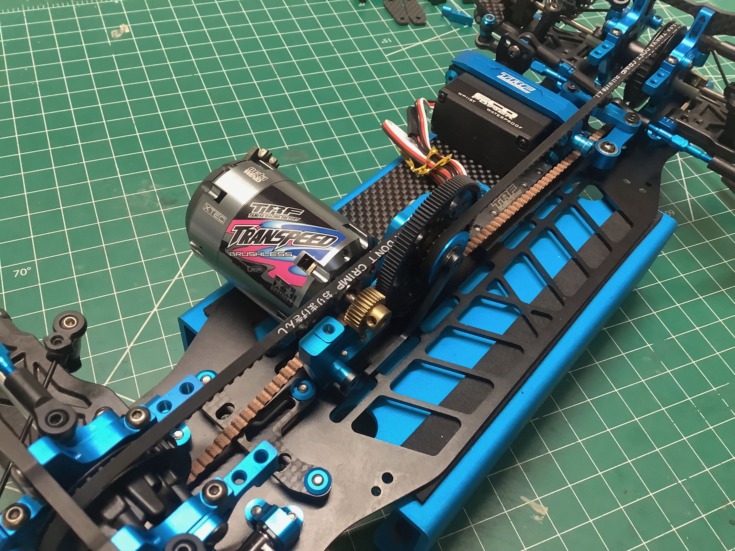
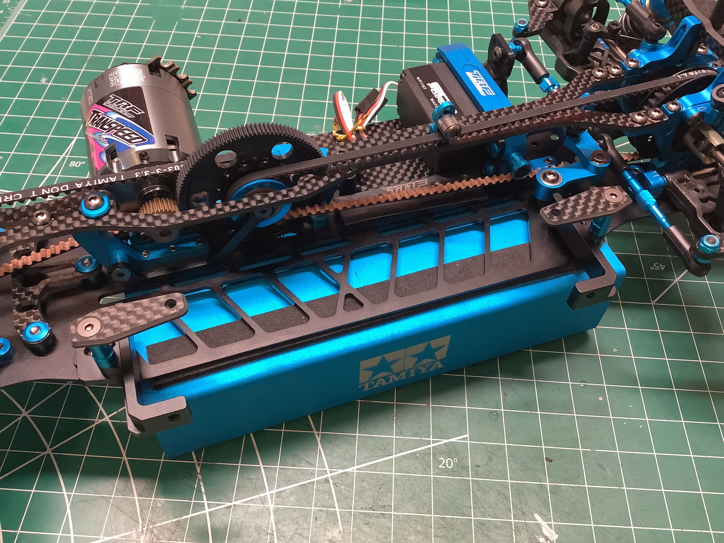
TRF kits had not included a pinion in years, but the TRF 420X comes with
a 30T aluminum pinion gear. I'll be using a cheaper brushless
motor for display, but for now I've installed a Tamiya Transpeed
motor. The picture on the right shows the important impact of
moving the center shaft forward of the motor. The front belt is
always on the right side of the spur so when the motor was ahead of the
spur there was plenty of room for the belt. Now that the motor is
behind the spur, it is much closer to the rear belt which is always on
the left side of the motor. You can see how the belt actually
passes between the pinion and the motor housing and how it just
clears the center bulkhead. The pinion position has to be adjusted
just right so nothing contacts the belt.
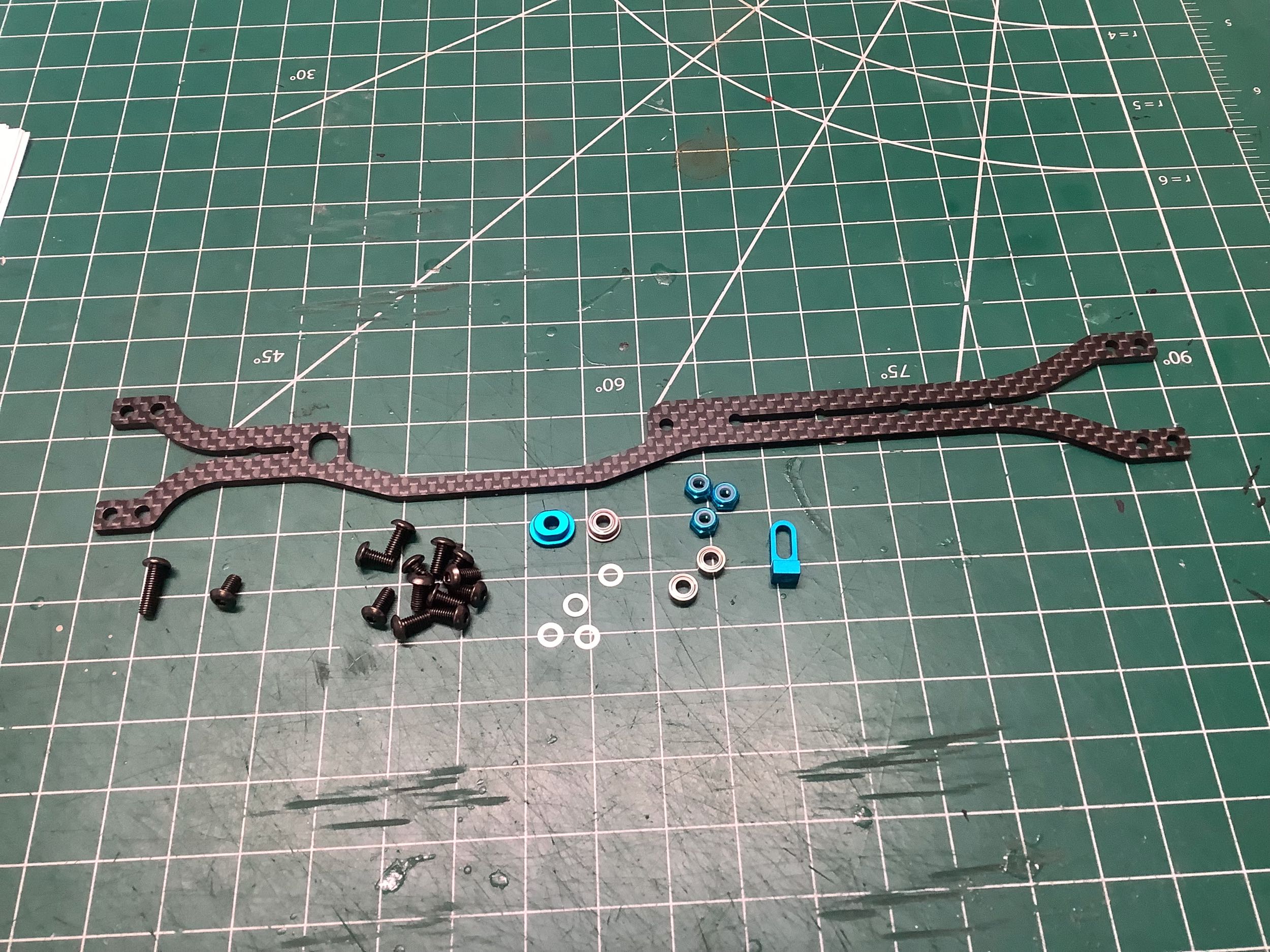
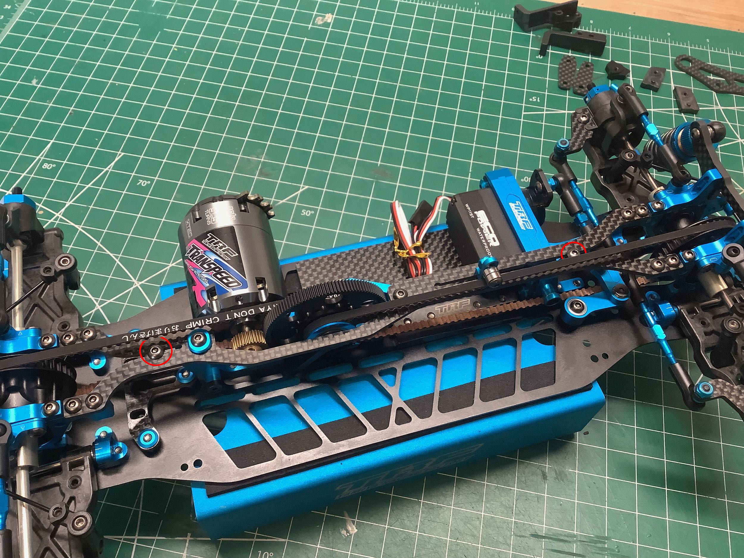
This upper deck is a departure from the design used on any previous
model. With a long slot running along almost the entire front and
rear length, it offers very little stiffness. However, if optional
screws are installed in the slot (circled in red on the right), then
the stiffness is increased.
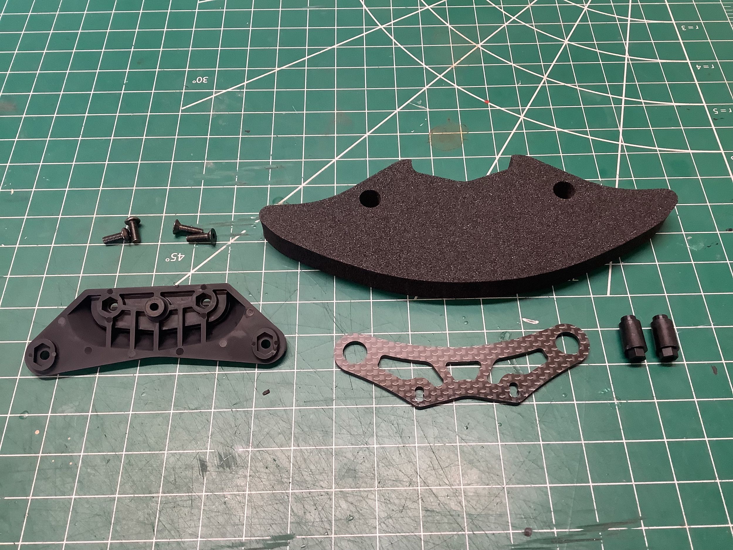
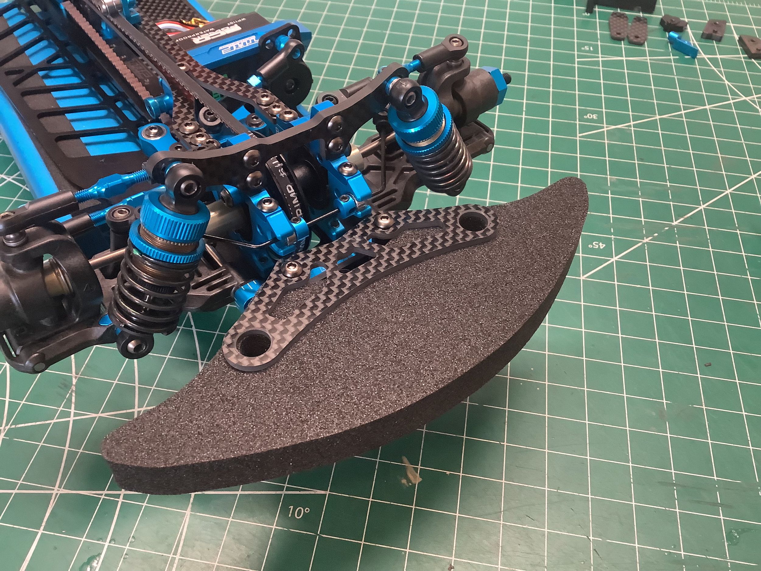
We haven't seen a new bumper and support for a long time either, but
these are both new for the TRF 420. The foam bumper is more curved
than prior versions. The carbon bumper support is also new but
very similar to older versions.
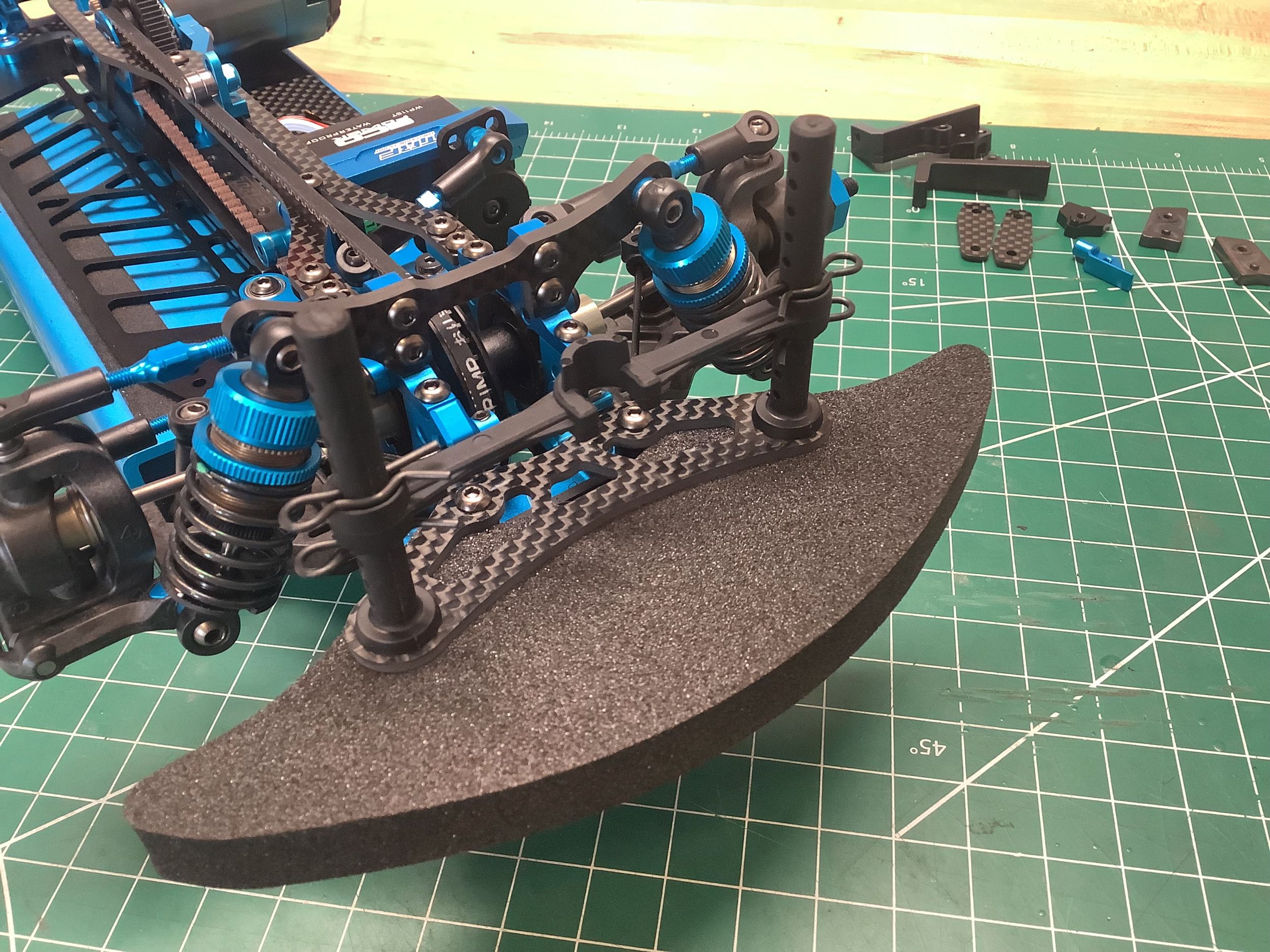
The body posts are also new and are easily distinguishable from the
prior version by their squared off top. Once trimmed to length
though, this difference will be eliminated. The transponder stay
you see between the front posts is an included option.
These battery supports have been continuously evolving. The TRF
419 used pathetic tiny plastic bumpers which required glass tape for
battery retention. The 419X added some sliding metal supports
which attached directly to the glass tape instead of having to thread it
through the chassis plate. The XR added steel L-brackets which
were much more secure. The TRF 420 improved further upon these and
made them aluminum, but still required glass tape. Finally the
420X includes the little carbon tabs shown which eliminate the need for
tape entirely.
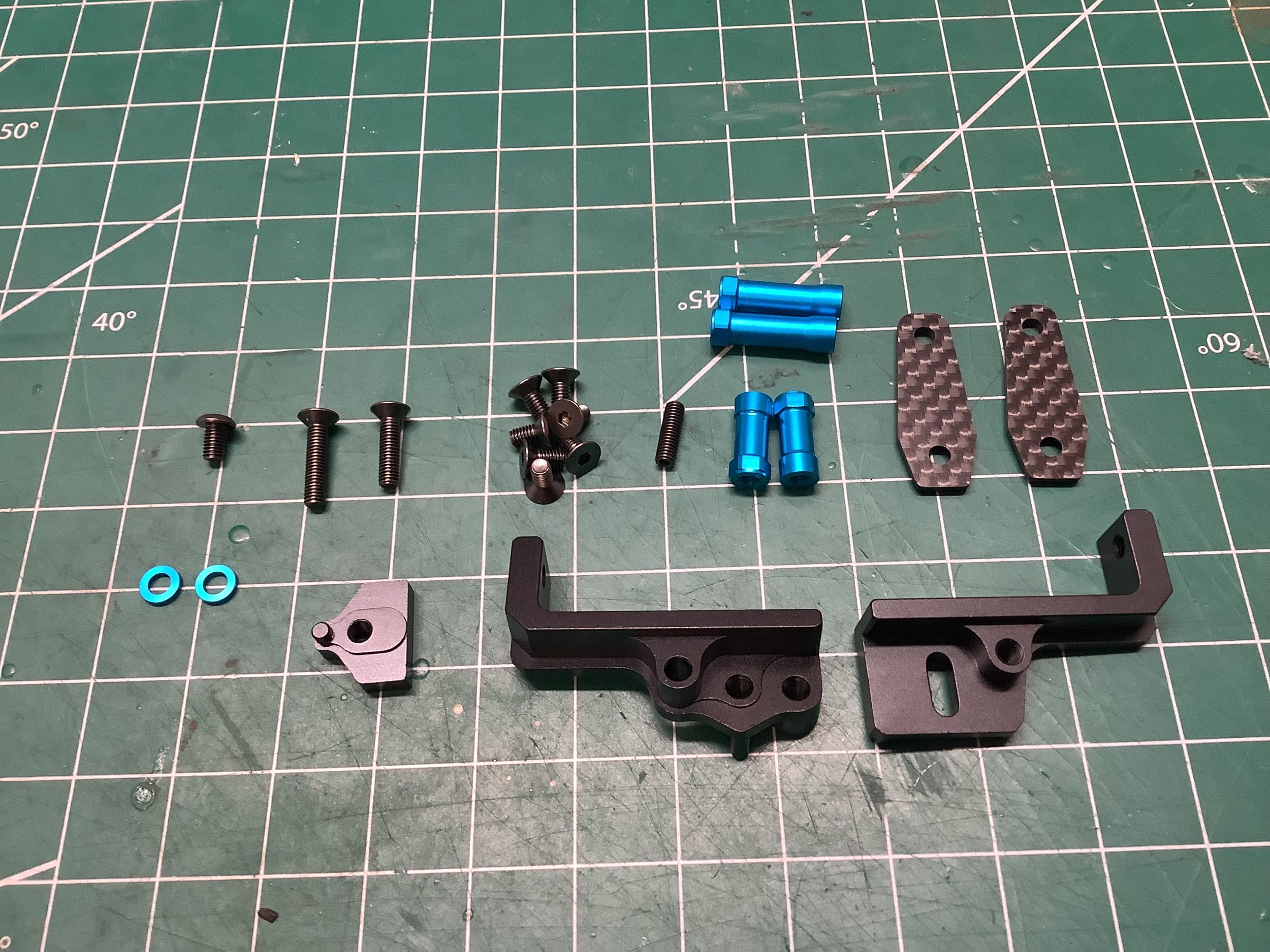
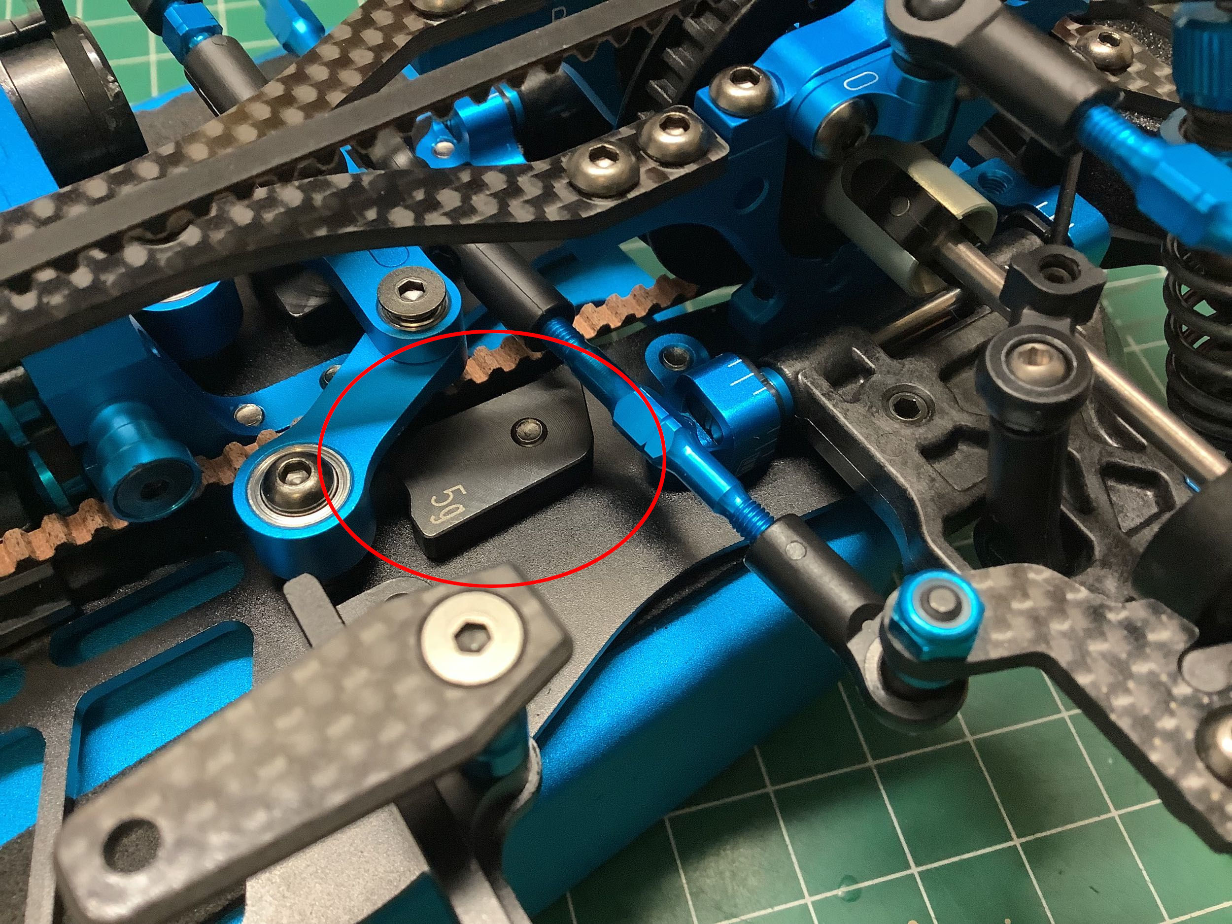
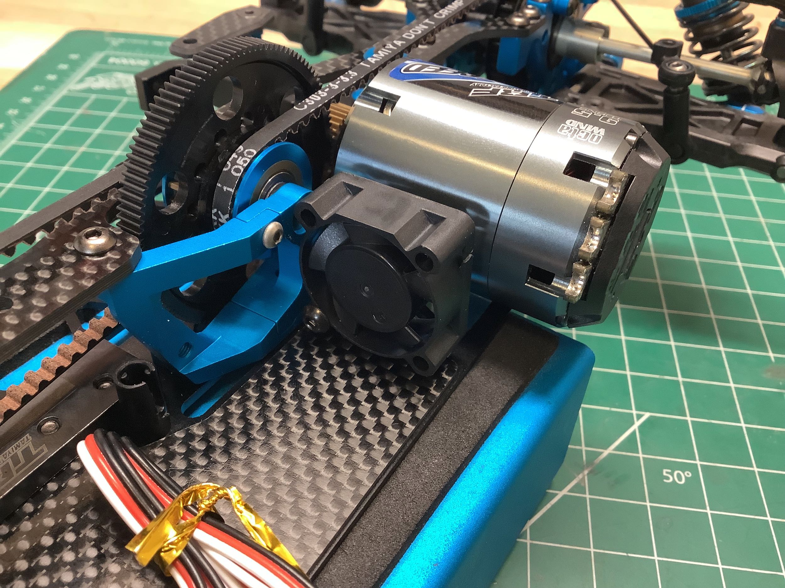
These images show some optional extras included with the TRF 420X.
The left hand image shows one of the 5g forward ballast weights.
The right hand image includes a cooling fan for the motor attached to an
optional mount which differs from that available for the TRF 420.
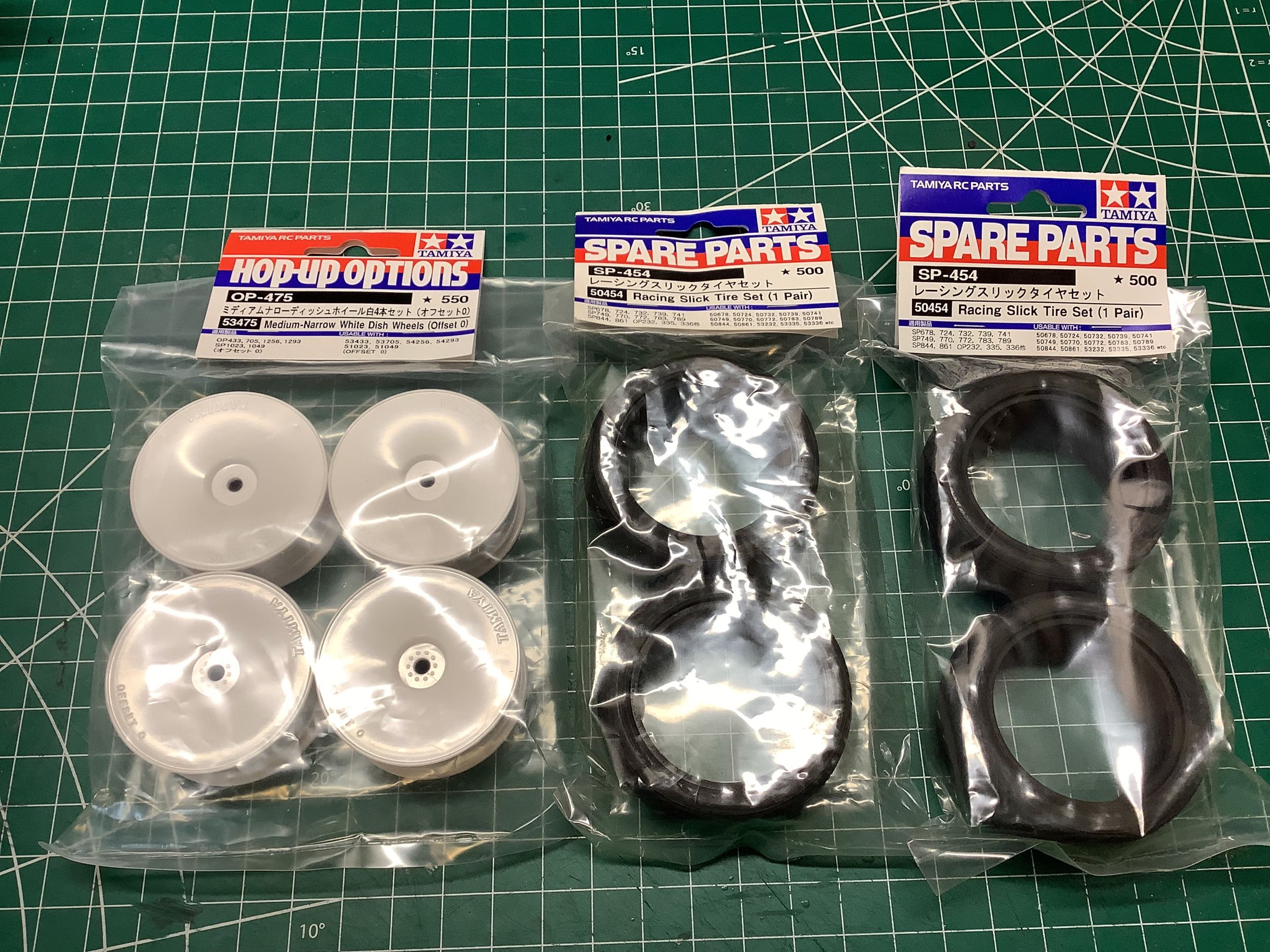
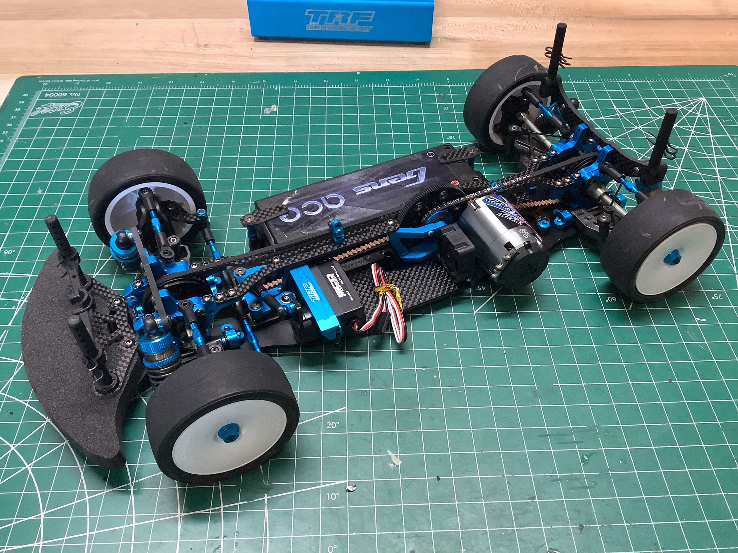
As usual, I added my own dish wheels and standard slick tires to
complete the chassis. I also installed a 2s hard case battery pack
just for the photo. I ended up removing the electronics tray for
display after this photo was taken.
©2025 Eric Albrecht