Tamiya Fuel Tank Trailer Project
Page 2: Adding motorized legs
The trailer is completely done and usable at this point, but I still
have one more accessory to add: motorized support legs. This will
allow me to control the trailer legs from the transmitter and therefore
couple and decouple without ever touching the truck. Considering
that all the electronics are in the tractor, controlling legs on the
trailer is no small feat. The way it is accomplished is quite
ingenious.
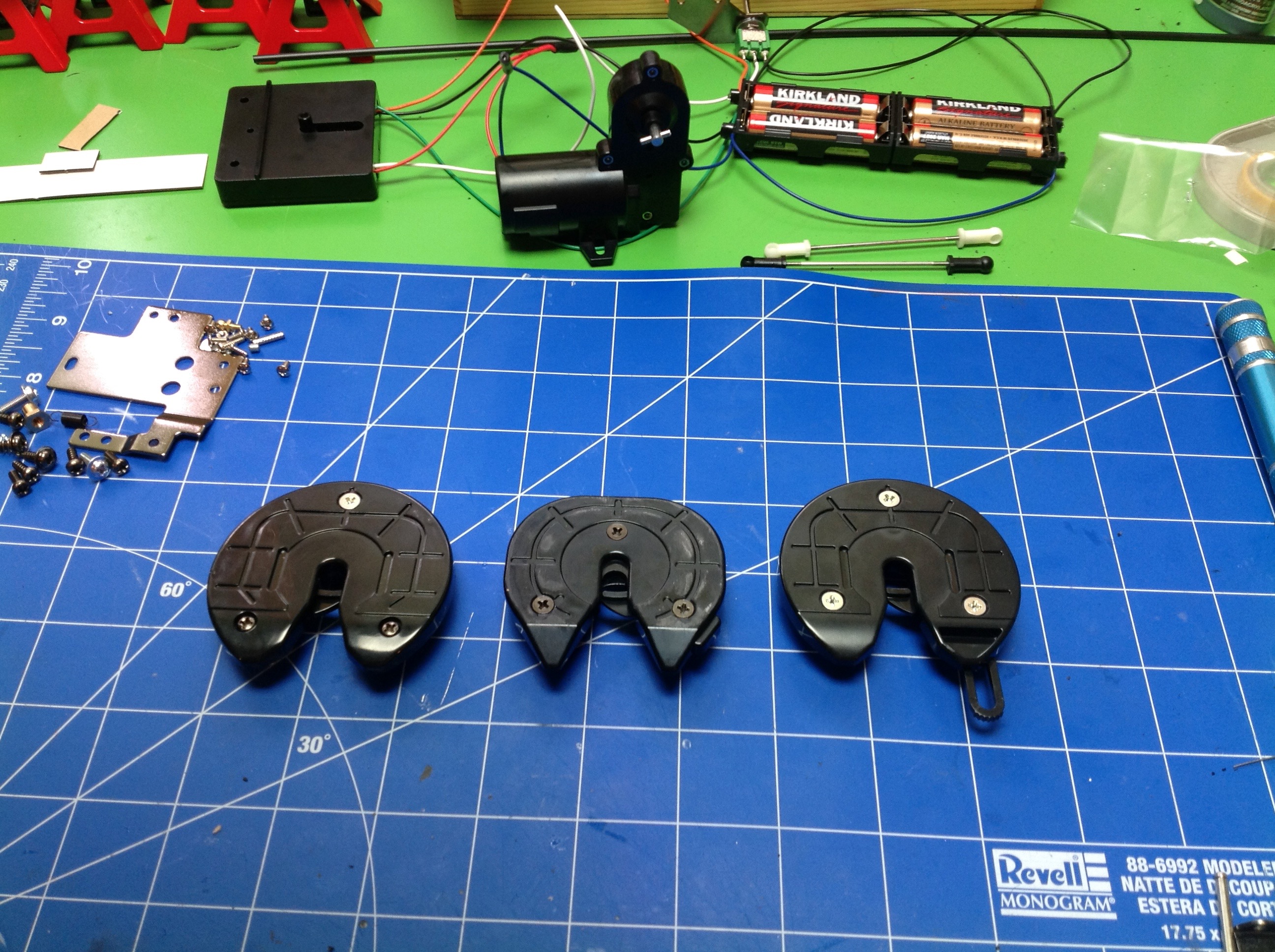
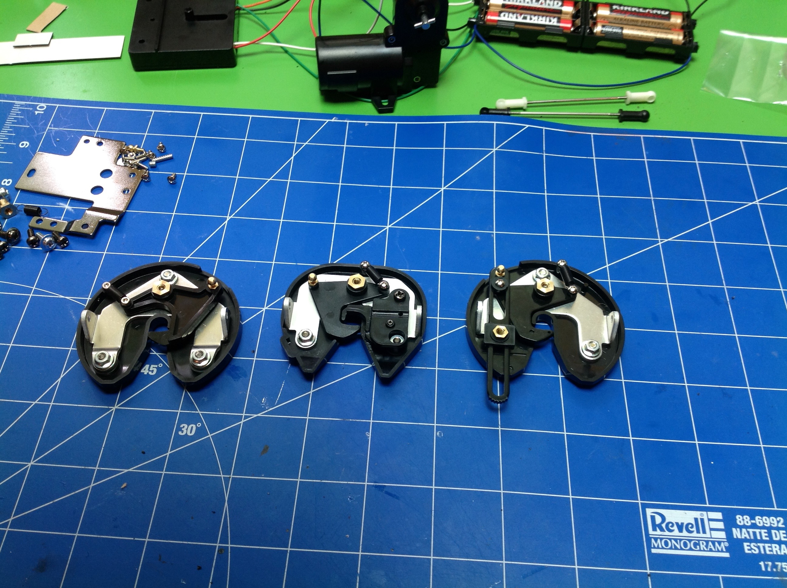
The first steps are actually performed on the tractor. Step 1
is removing existing parts. At this point I've built three
different 5th wheel units. The first, on the left, is the stock
unit which uses a manual release. The second, which is shaped
differently, came with the MFC and adds a micro-switch so the controller
knows when a trailer is coupled. The third comes with the support
legs and looks like the first except that it has a slotted link as you
can see on the lower right. This is the part that mechanically
interacts with the trailer to send commands to the legs. It has
little serrations on the end to keep it from slipping against the
trailer trigger. There's also a fourth coupler option, the one I
actually used. You see, you don't need the MFC to use the
motorized legs, you can just control them with a Channel 4 servo.
However with the MFC you get extra functions, so that means I need to
move the micro-switch from the 2nd coupler to the 3rd. This was not
at all obvious from the instructions so I was frustrated for a bit
whilst I figured it out.
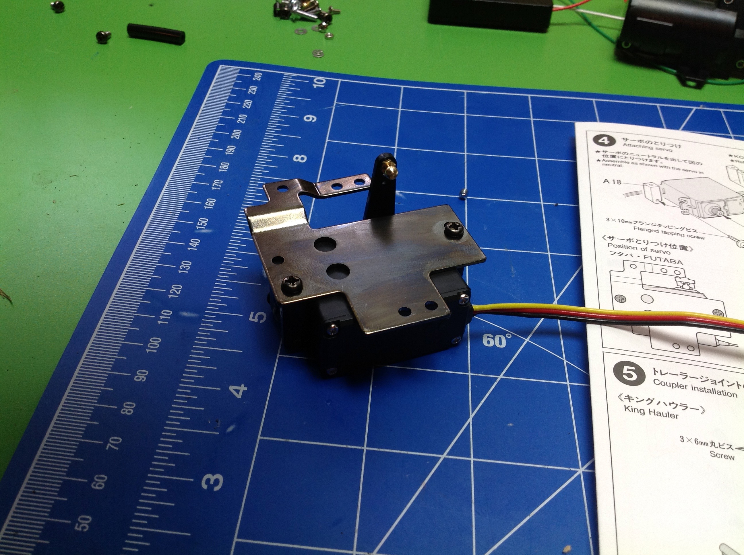
Here is the mount for the 4th channel servo. This will go right
behind the cabin, hidden between the frame rails. If will actuate
the slider on the 5th wheel. A small motion back tells the legs to
retract. A large motion back tells the legs to extend. The
trailer distinguishes the two by having two micro-switches and looking at
the relative states of the two. There are no circuit cards
involved though, just simple wiring. Movement of the servo forward
releases the coupler. There's enough lost motion in the slider
that aft movement doesn't affect the coupling hook. The hook
itself locks over center so that thrust loads on the kingpin do not tend
to release the hook.
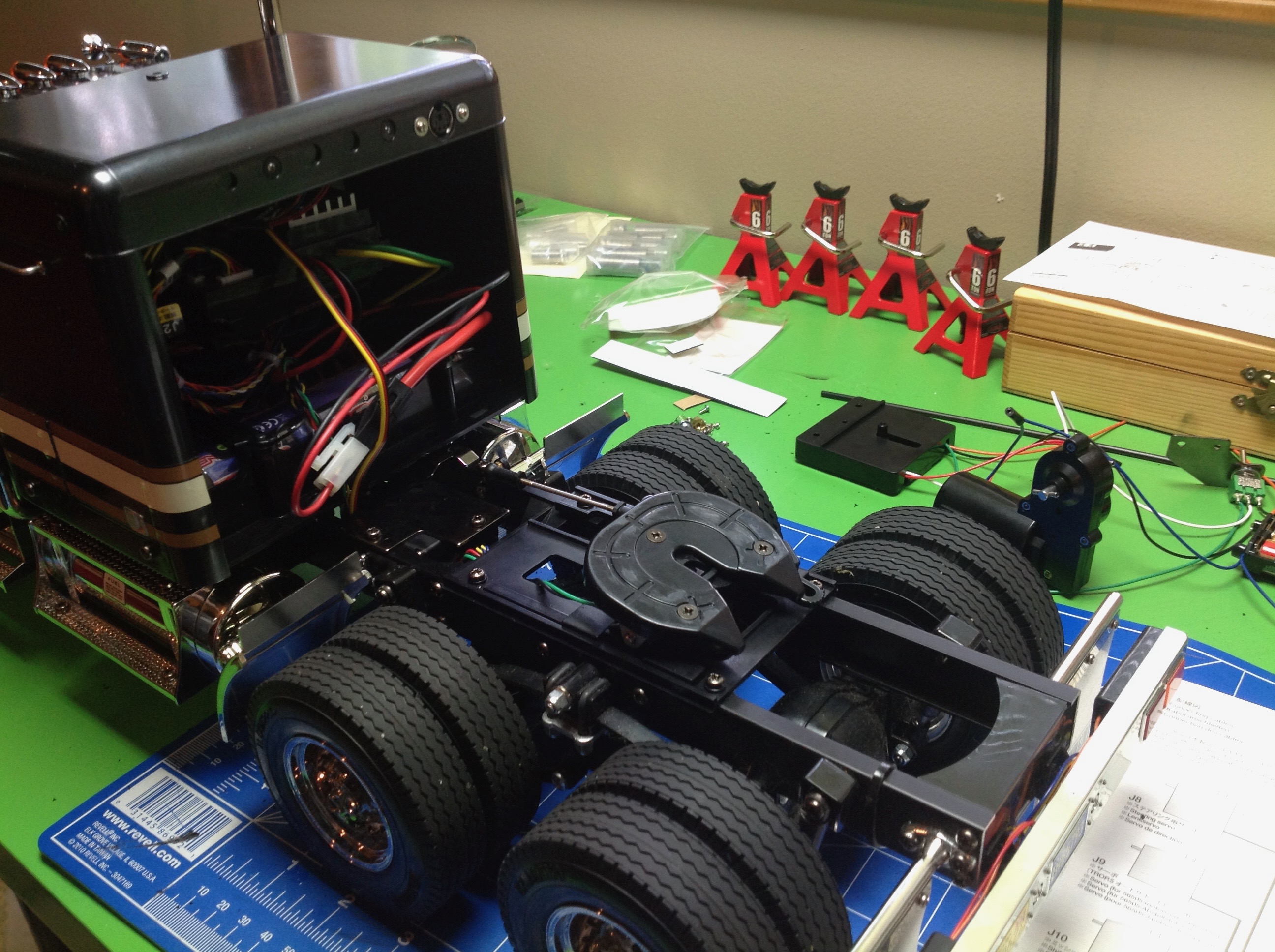
Here in Step 5 the coupler and servo have been installed on the
tractor. The servo needs to be wired into the MFC. The port
you see at the upper right of the sleeper opening is for trailer lights
which, sadly, still need to be attached manually. Since this is
how real trucks do it though, I can hardly complain.
Step 6 removes the old trailer legs and associated mechanism (a bit of a
shame) and Step 7 builds the battery box. That's right, you
actually have to build the 4AA battery box including putting in the
terminals and attaching the wires. They have a clever solderless
system which uses little bits of rubber tubing. Step 8 builds the
micro-switch can. I didn't take pictures of any of that.
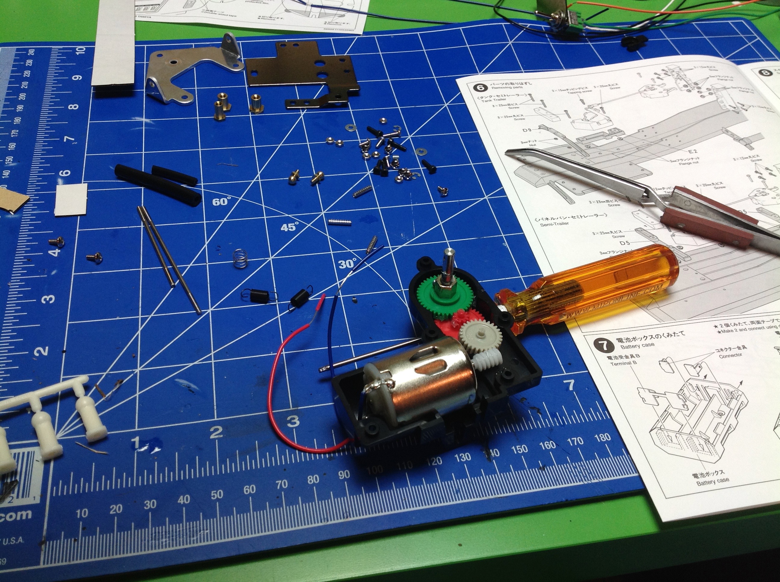
This
is Step 9 which is the gearbox. You can see a little motor (370
sized) driving a worm gear. Using a worm gear is important so
weight on the legs can't backdrive the motor. There are 3 total
stages of gear reduction not counting the rack gear on the legs themselves.
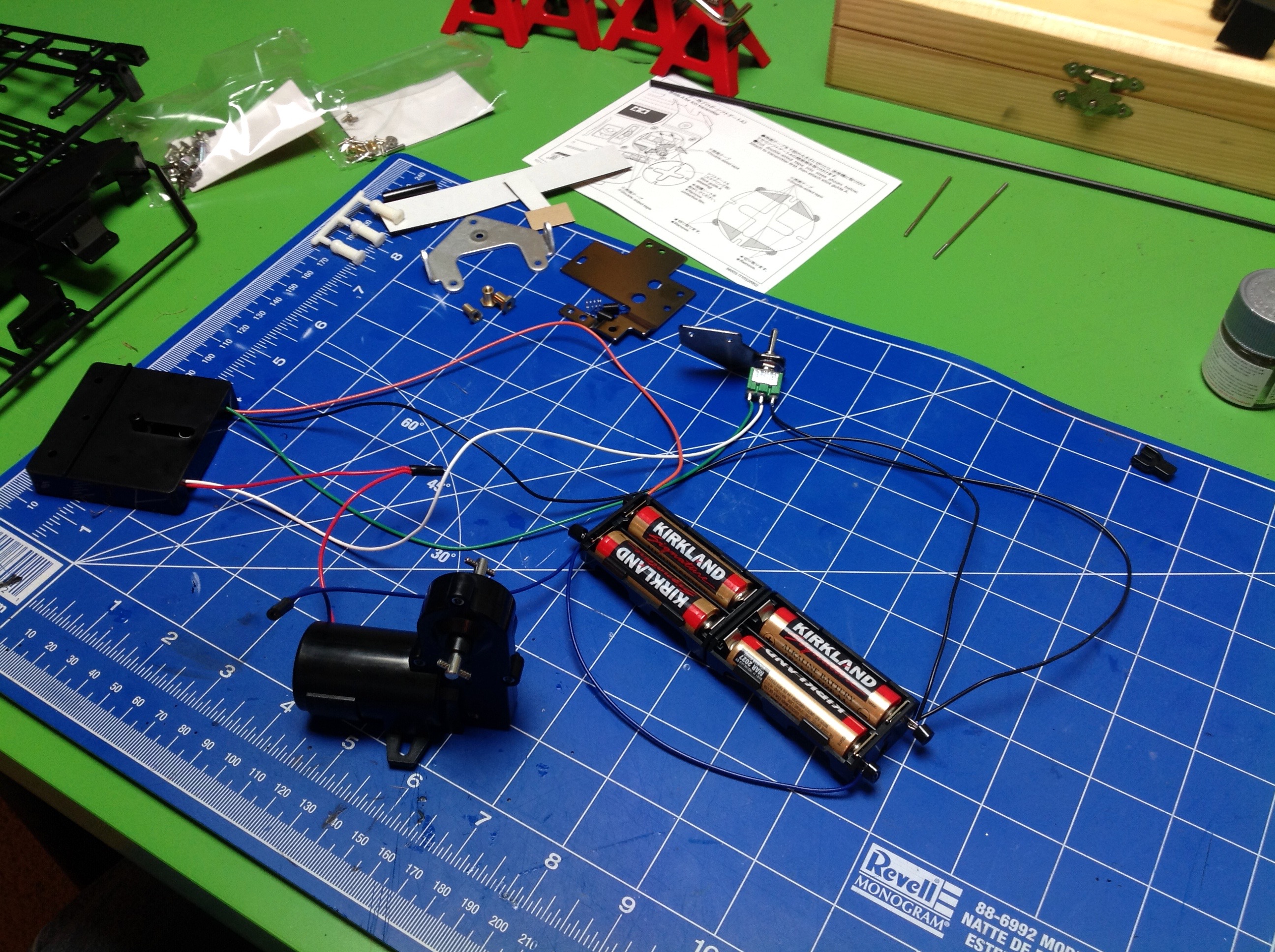
At this point Step 10 tells you how to wire everything together and it
isn't trivial. We have two micro-switches, leads to 4 batteries, a 3
position toggle switch for manual operation, and a motor. All
these wires need to be carefully routed and hidden within the trailer
frame. Wouldn't want anyone to know it's a model!
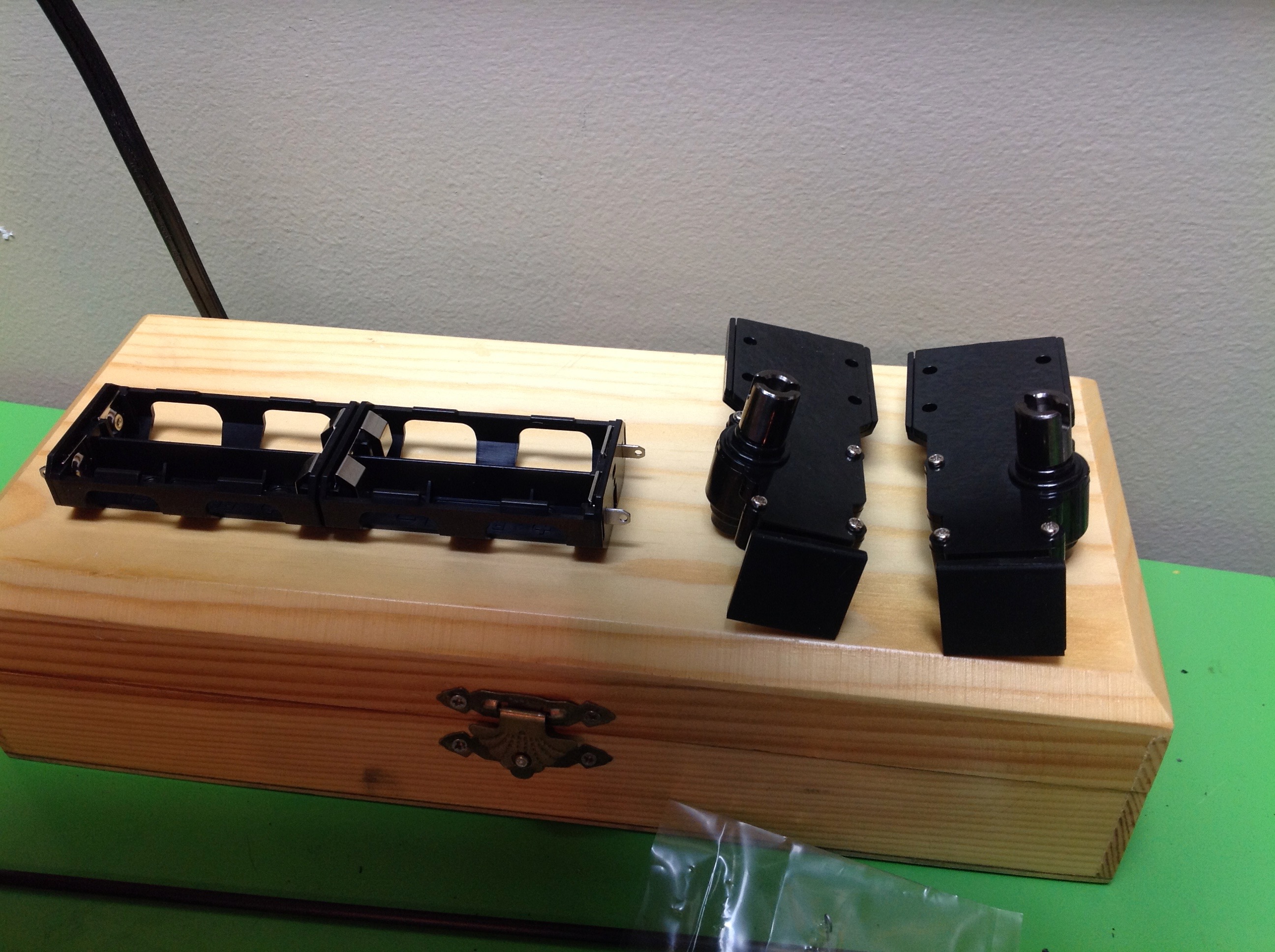
Here is the battery box and the completed motorized legs from Step
16. Inside each leg is rack and pinion gear along with a spring
loaded clutch system which allows the pinion gear to slip if you keep
driving after you reach the end of travel, but without dropping the
trailer.
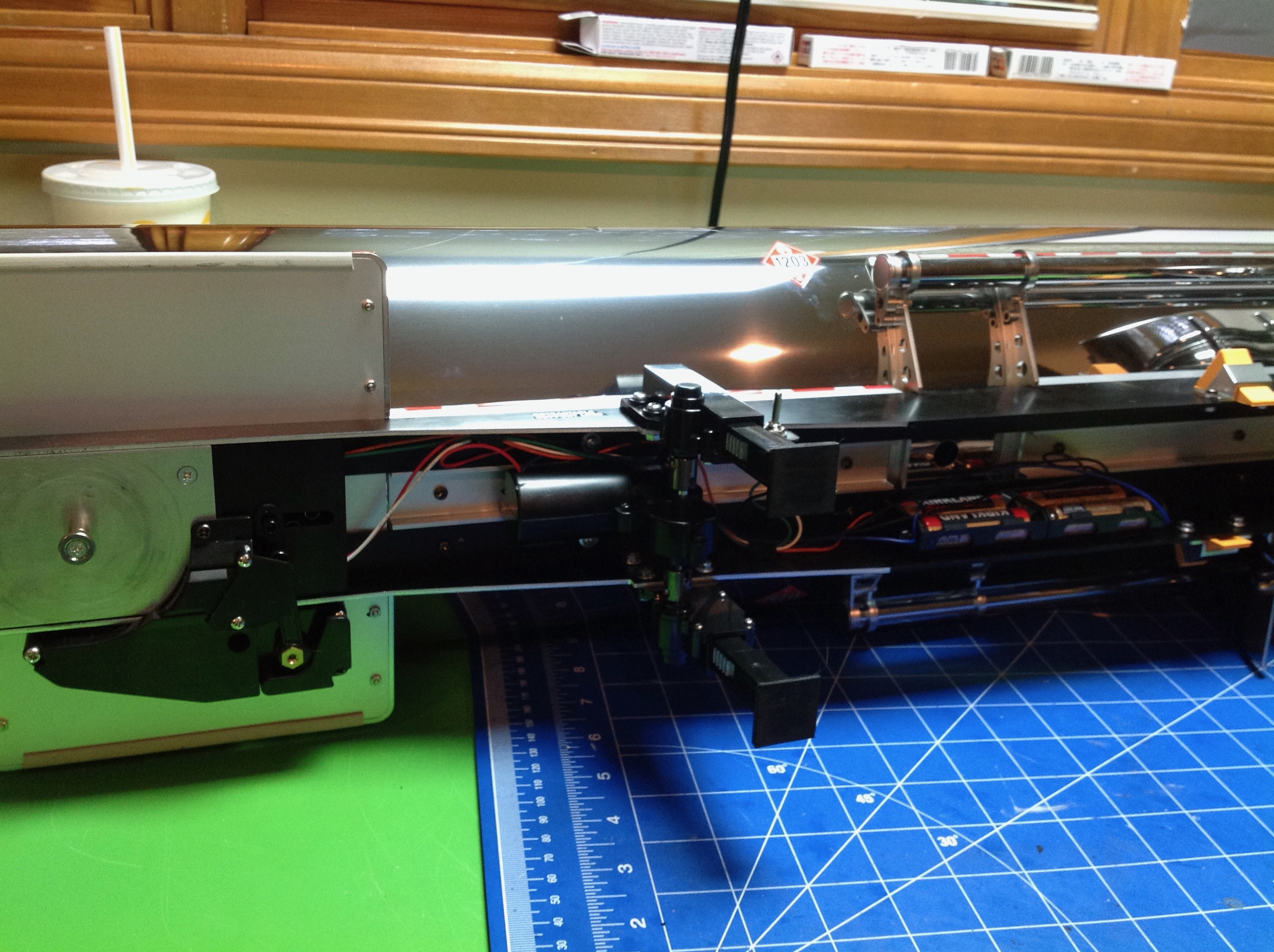
This bottom view of the completed trailer shows the wiring, battery box,
and motorized support legs. The wires can't be seen when the
trailer is upright.
©2017 Eric Albrecht