Arocs Tipper Project
Page 2: Upgrades!
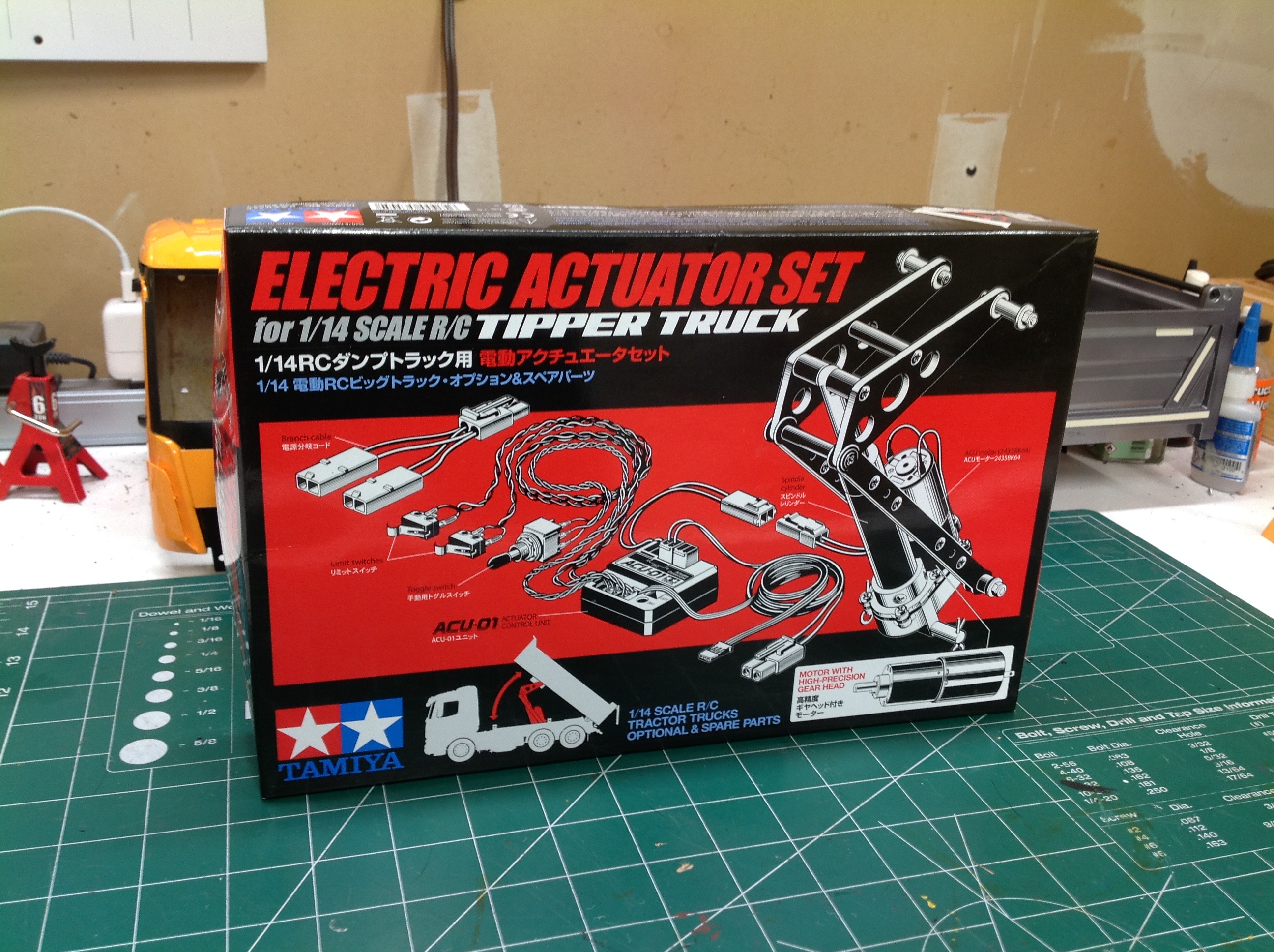
When this model was announced, I was surprised to hear that the tipping
actuator was not standard. It is quite a shock to learn how much
extra you have to spend to get this option, and you may not understand
why it costs so much since it is "just a screw". As you'll see
below though, there is a lot involved in this optional actuator set, and
many of the parts are steel or aluminum. I highly recommend
adding it if you own this truck since tipping the bed is the point of a
tipper truck.
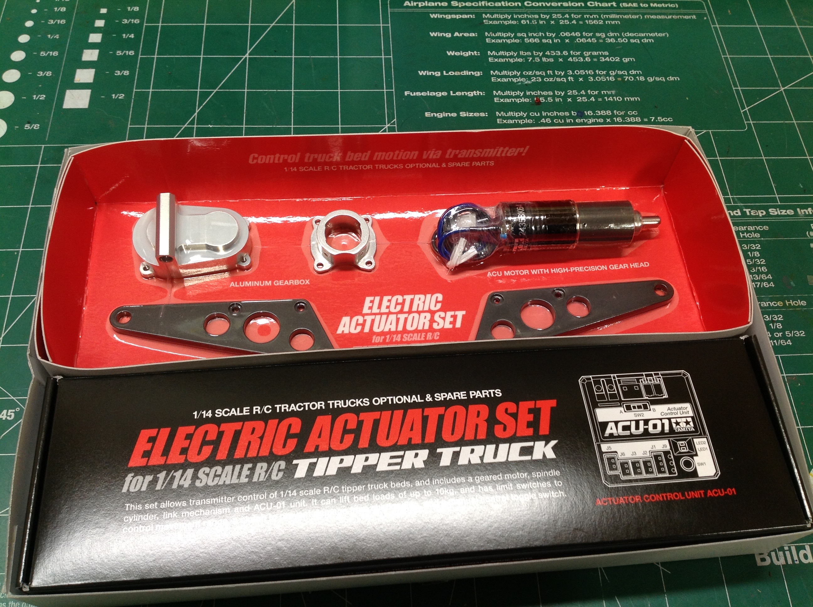
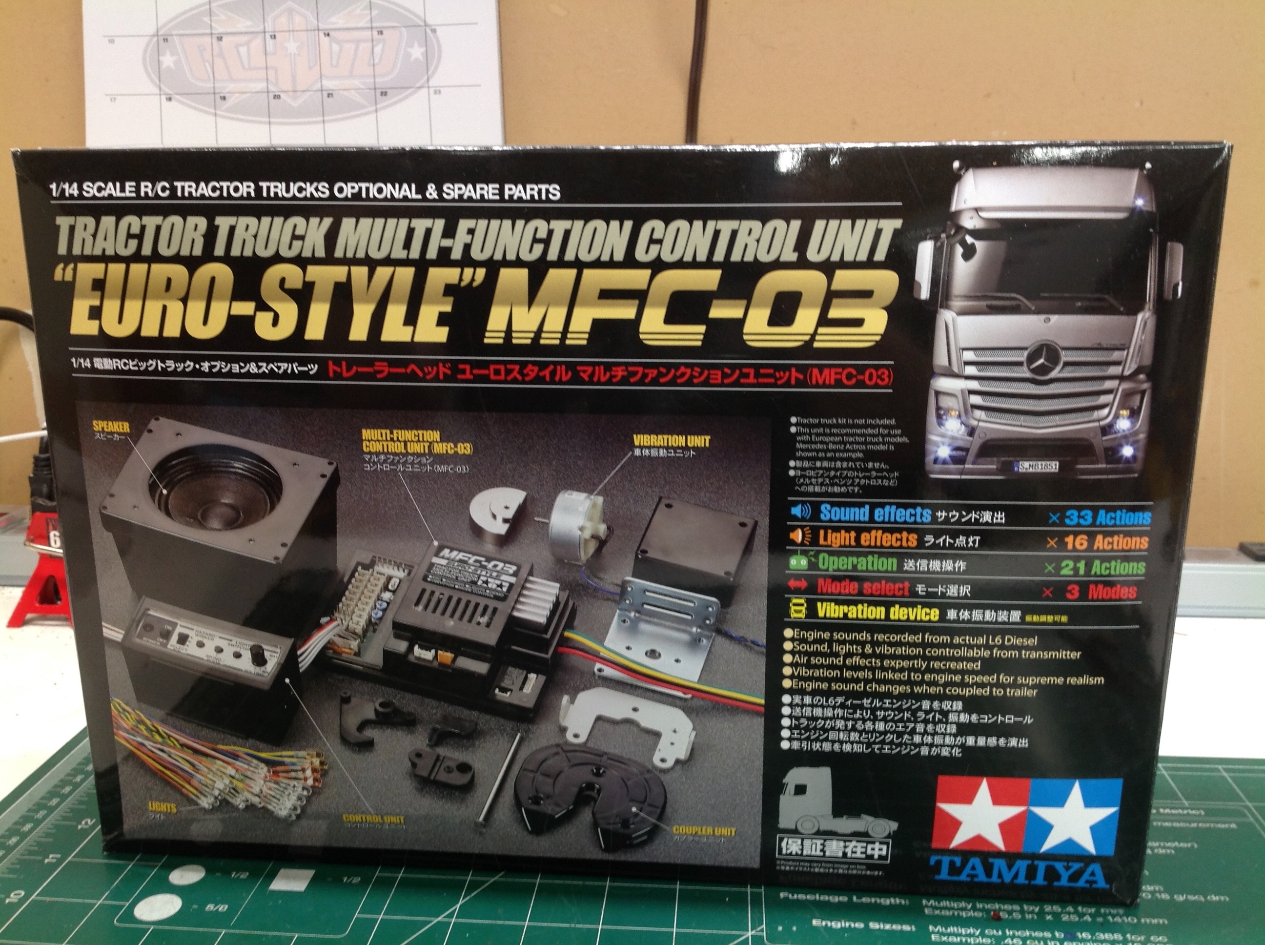
Here's a good look at the contents of the box. There is a more
here than you might expect. The actuator must be able to lie
horizontally when retracted, but then pivot to vertical when
extended. This is the only way it will fit between the chassis
rails and also extend far enough to lift the bed. This requires a
mechanism. The electric motor must also be geared down heavily to
lift the potentially heavy load in the bed. There is a control
unit which takes the signal from either the radio or the manual switch
and translates it to a command. Use of the manual switch will
always move at full speed, while using the radio allows 3 speed options
in each direction. There are also limit switches to stop the
actuator when the bed reaches its end of travel. Without these,
the huge mechanical advantage of the motor could damage the bed or the
chassis running into the stops.
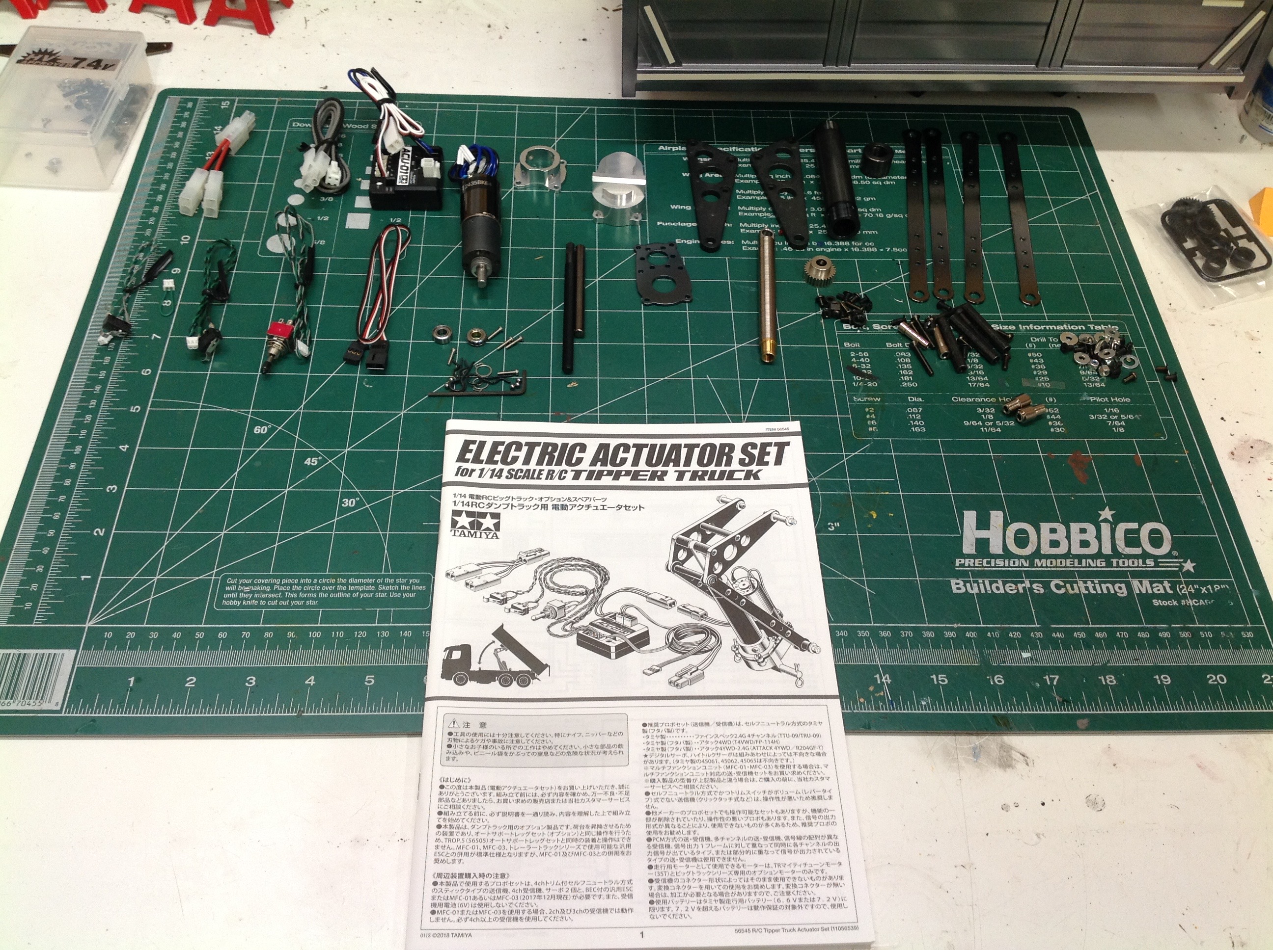
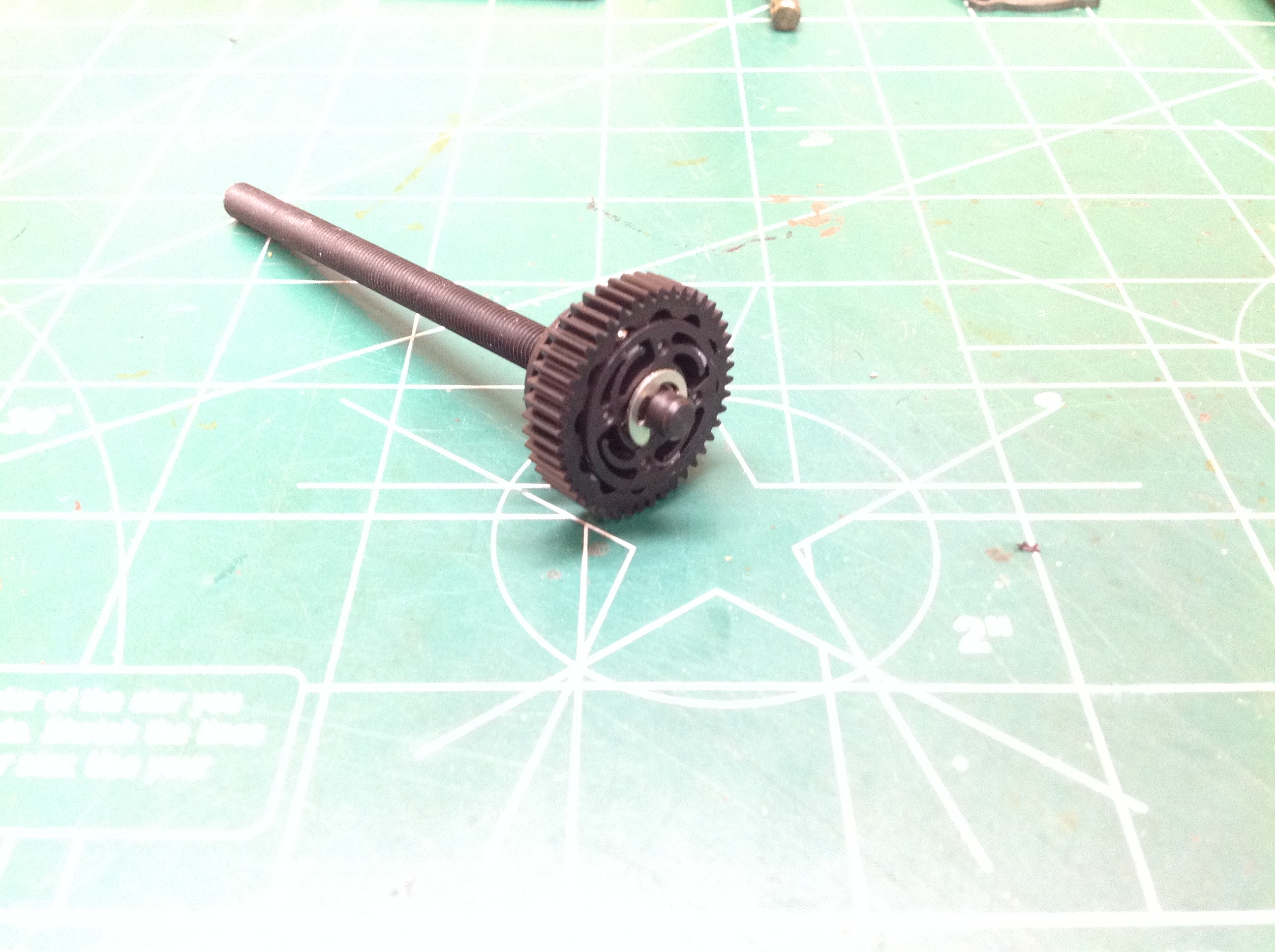
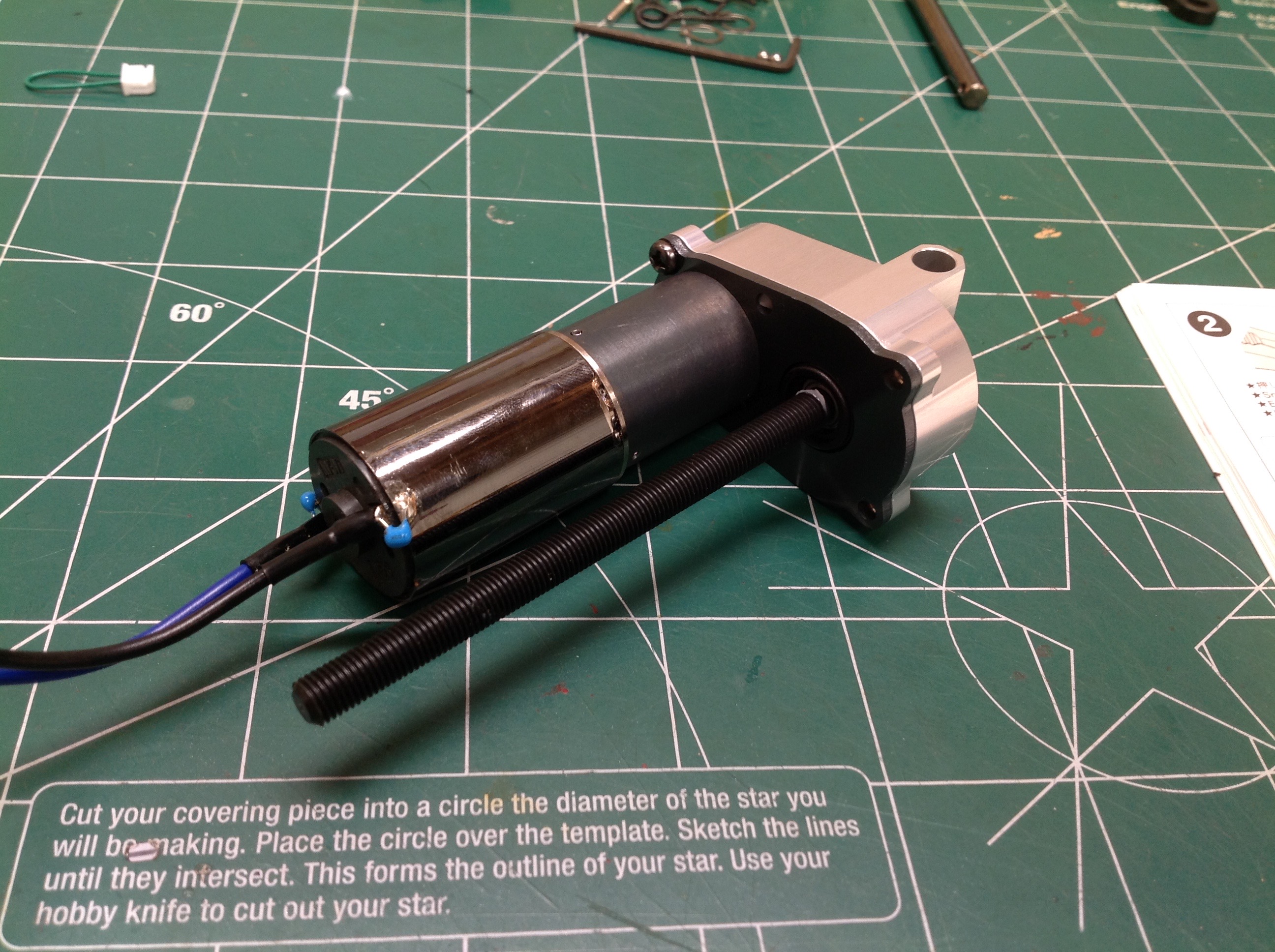
The part you see on the left is the main drive screw and bull
gear. If you look closely you'll see a ratcheting clutch built
into the gear to protect the system from overload. The right hand
image shows the main gearbox. The small motor is at top left and
is already connected to an inline gear reduction unit which results in a
very slow output. This thin directly drives a pinion which mates
with the bull gear. The gearbox housing is aluminum but the screw
appears to be steel (which makes it heavy). A thrust bearing sits
at the end of the screw to support the axial loads of the actuator.
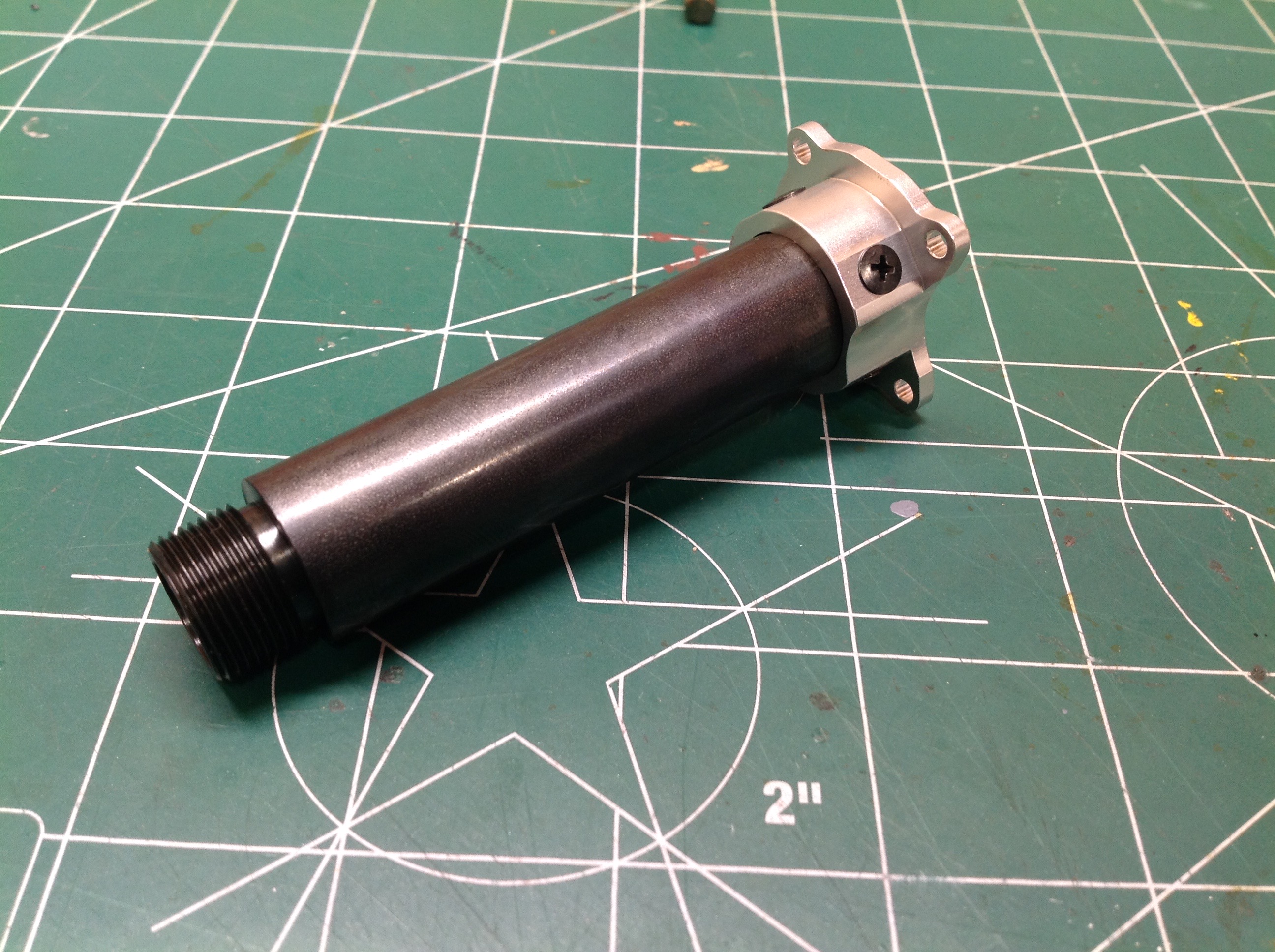
The traveling nut at the end of the rod is what extends the
actuator. The screws fits inside when the rod when the actuator is
retracted. The right hand image shows the cylinder (or
barrel). This would be a pressure vessel on a hydraulic actuator,
but here it really doesn't have any structural function. It makes
the whole thing look like a hydraulic actuator and it protects the screw
from dirt and debris.
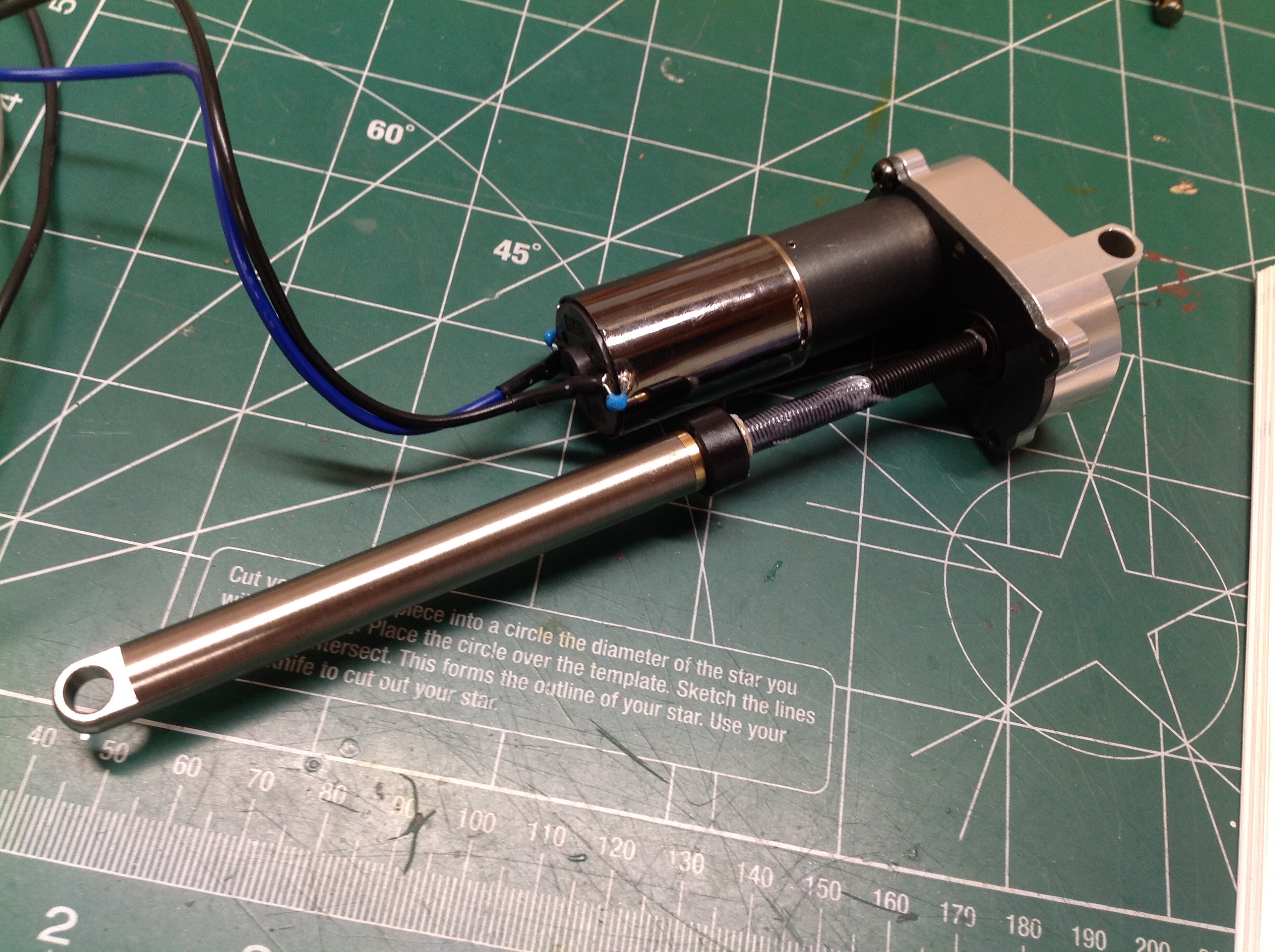
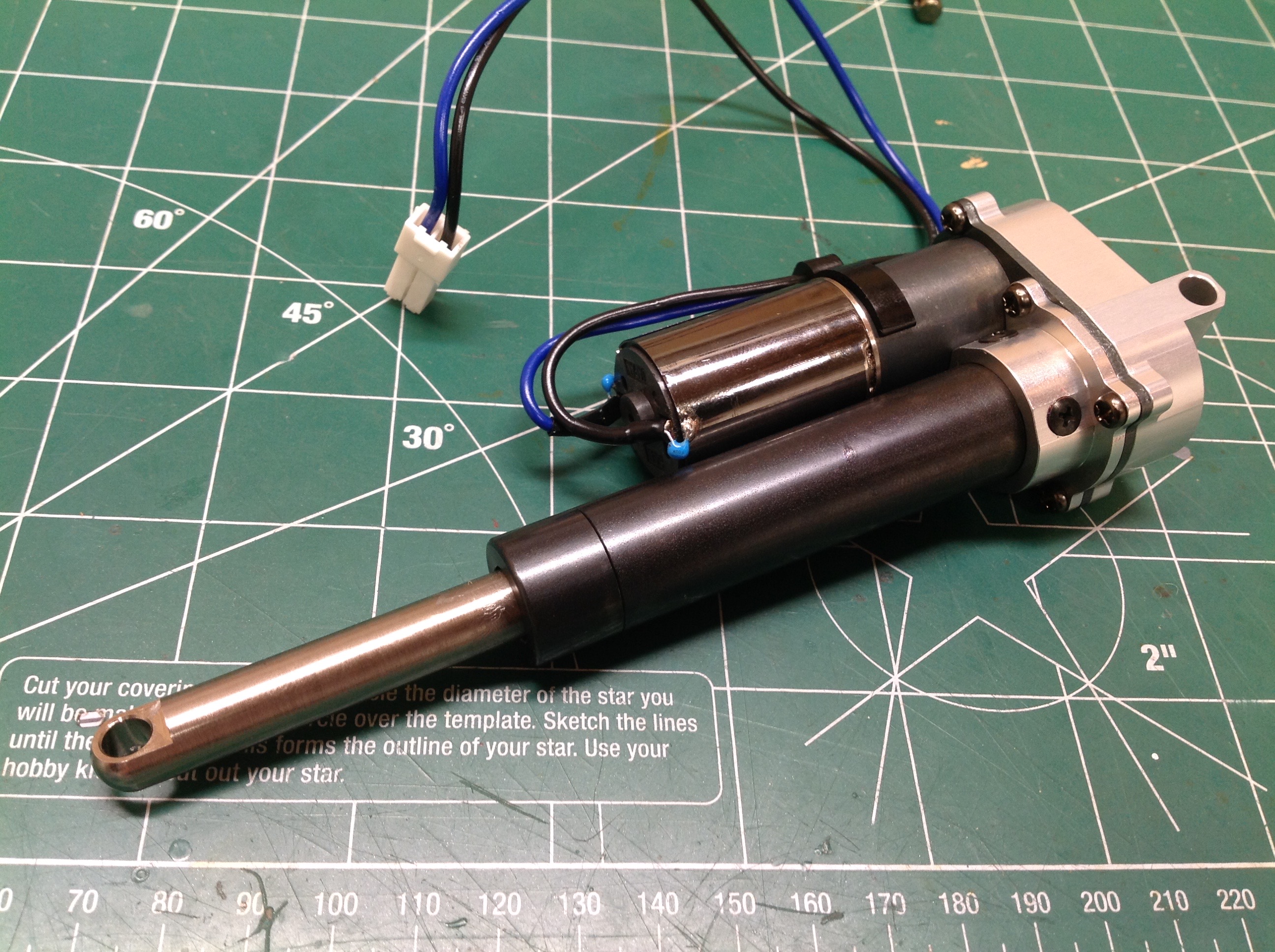
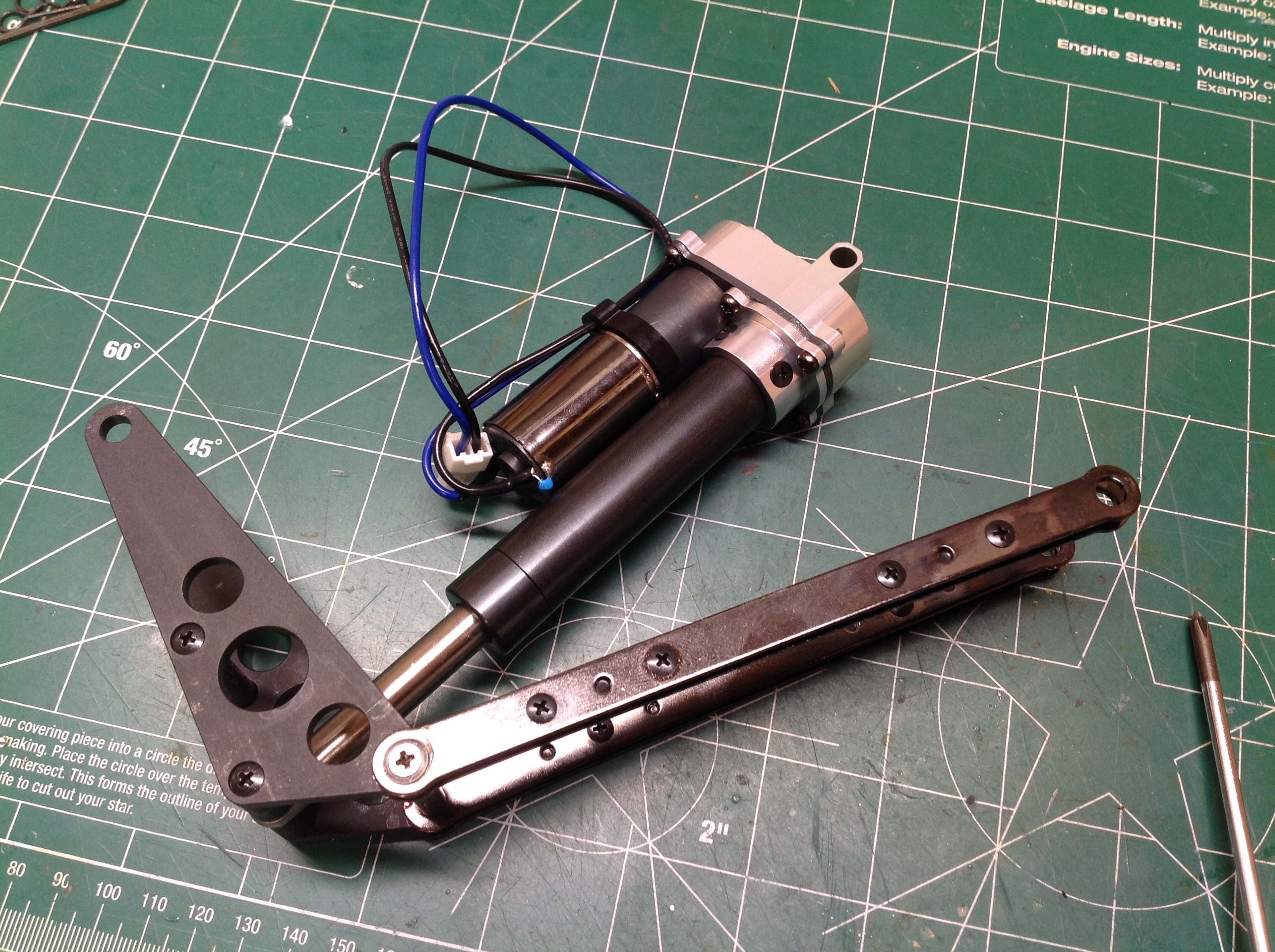
Here is the completed actuator with motor, gear reduction unit, gearbox,
cylinder, screw, and piston. On the right you can see the steel
plates which serve as links to control the kinematics of the
system. The upper end of the actuator connects to the links, and
the lower end will pin to the chassis.
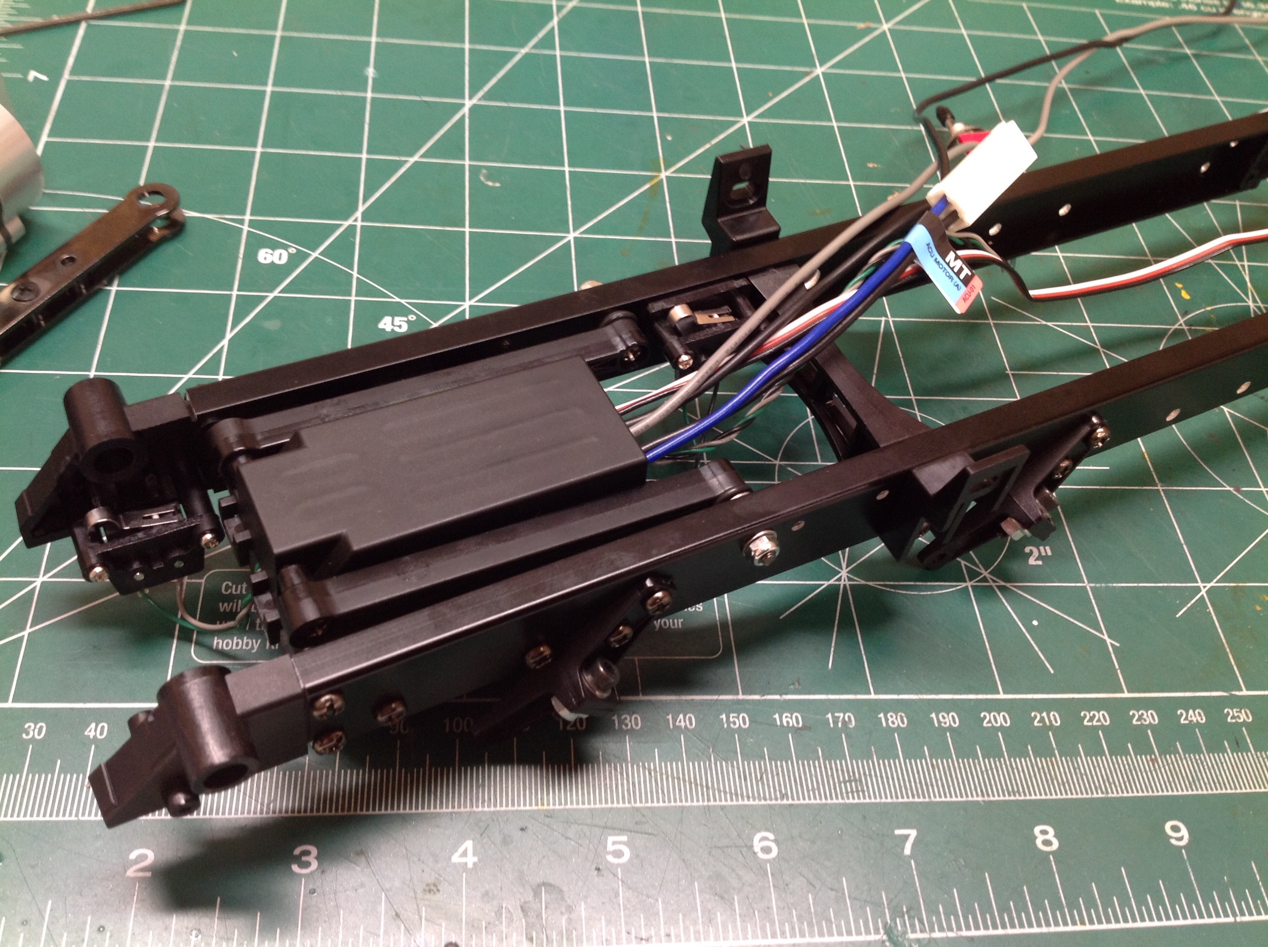
The control unit must be sandwiched into the plastic box between the
frame rails of the chassis. Into this you must plug the motor, two
limit switches, the radio connection, the manual switch, and
power. If that sounds like a lot of connections, it is. It
is tricky to get everything to fit in the box, especially if you'd like
to coil up any extra wire length in there and not have to secure it
elsewhere. In fact, routing the wiring is probably the most
complex part of the whole installation process. The actuator fills
all the space between the rails and it is very important that the space
be kept clear for movement. Any wires in the way will get
smashed. Yet, power and signal clearly need to run forward, and so
do any LED wires that might be going to the tail lights. The wire
going to motor must also be able to move through a large arc as the
actuator extends.
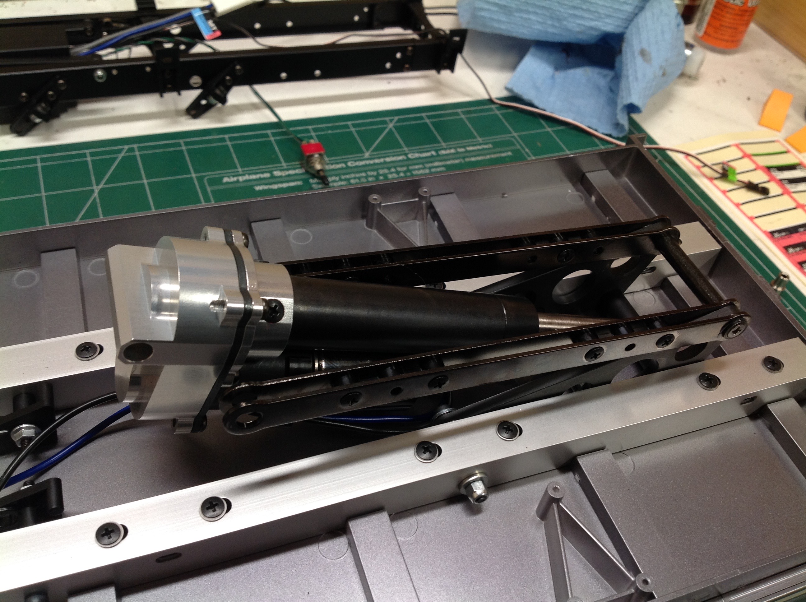
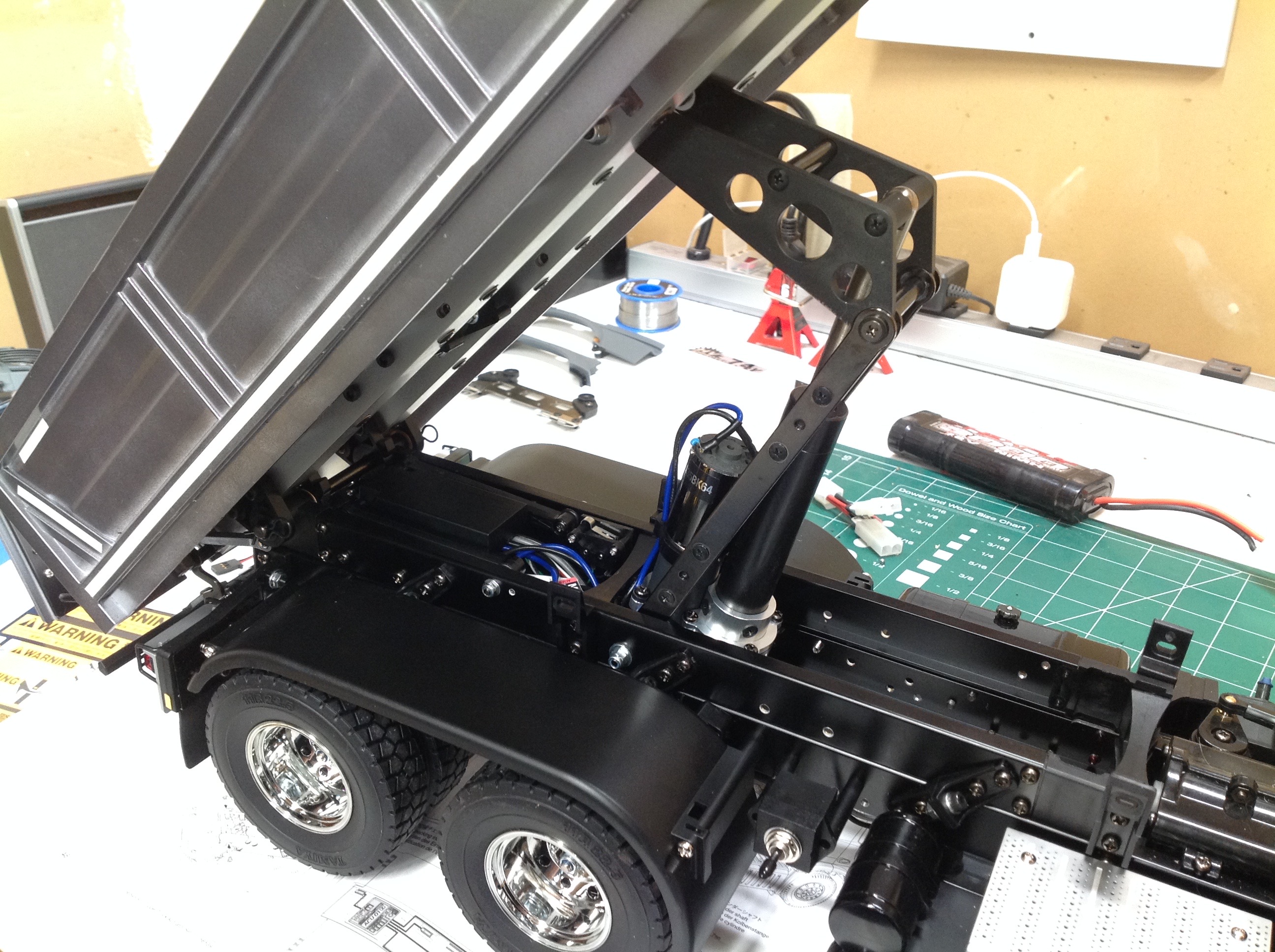
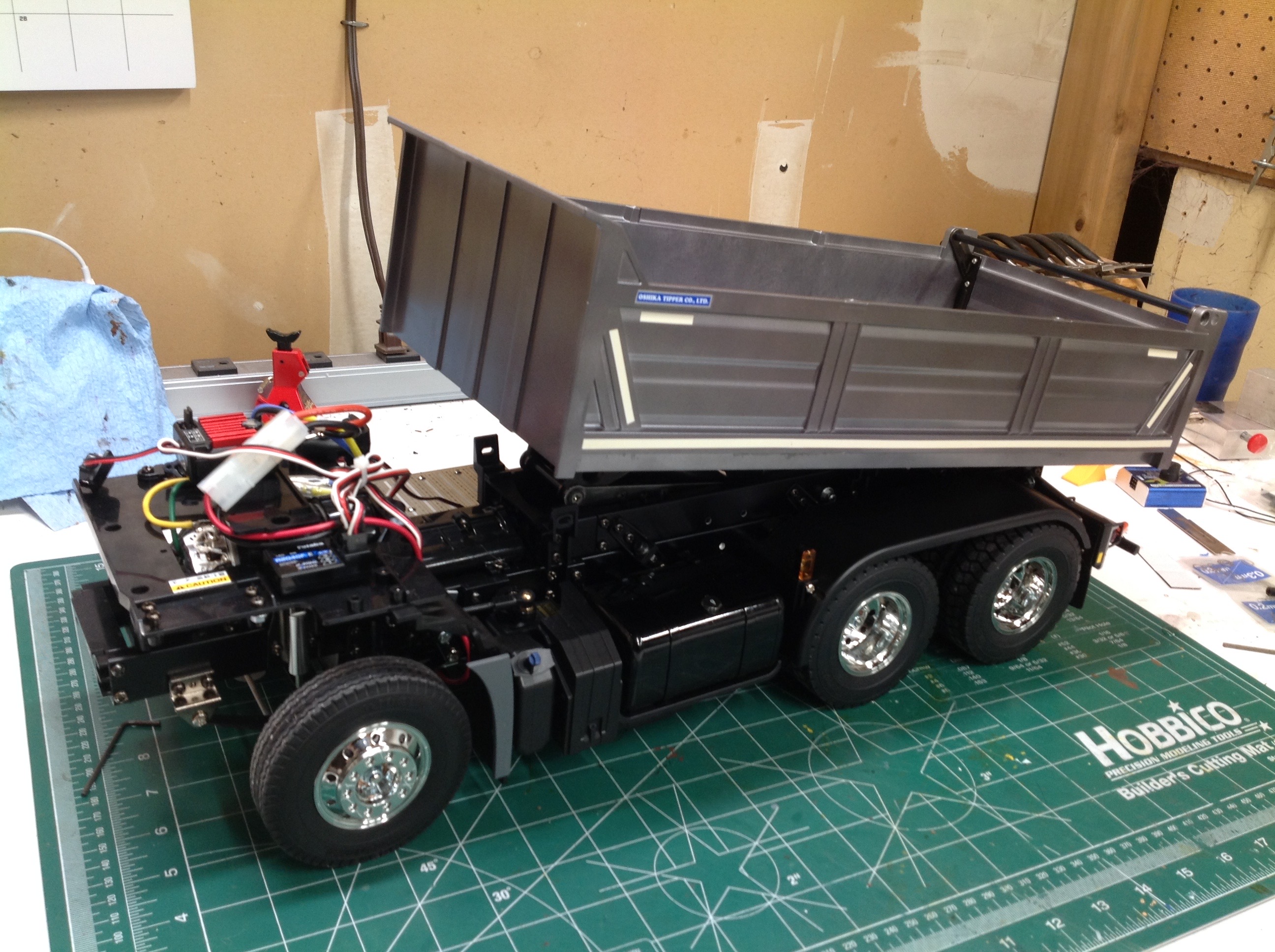
Here the actuator and the control box and installed to the bottom side
of the bed. Everything is unsecured at this point and quite heavy,
so the risk of pinching a finger is high.
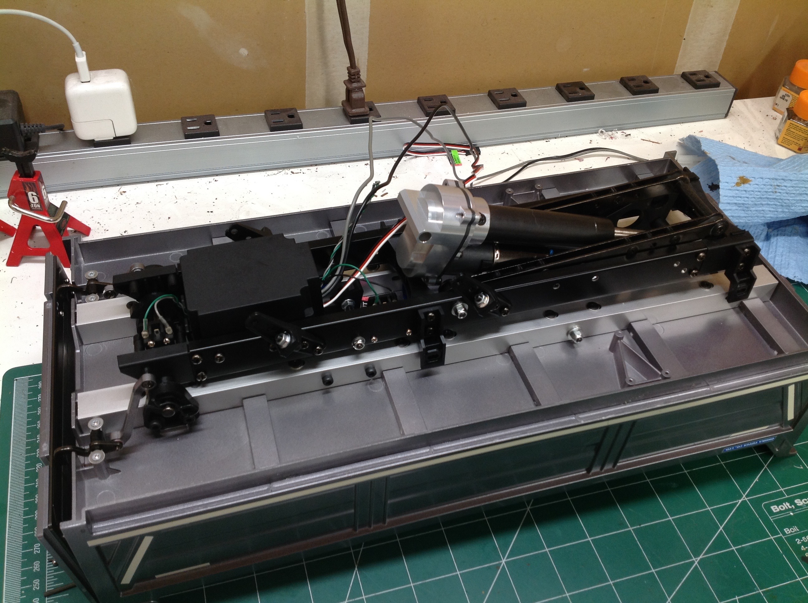
Here's the installed actuator in the raised position. Just behind
the oil tanks on the frame rail you can see the switch for manually
raising or lowering the bed. This will work whenever the battery
is plugged in regardless of whether or not the ESC is turned on.
This means you need to unplug the battery when not in use to avoid total
discharge.
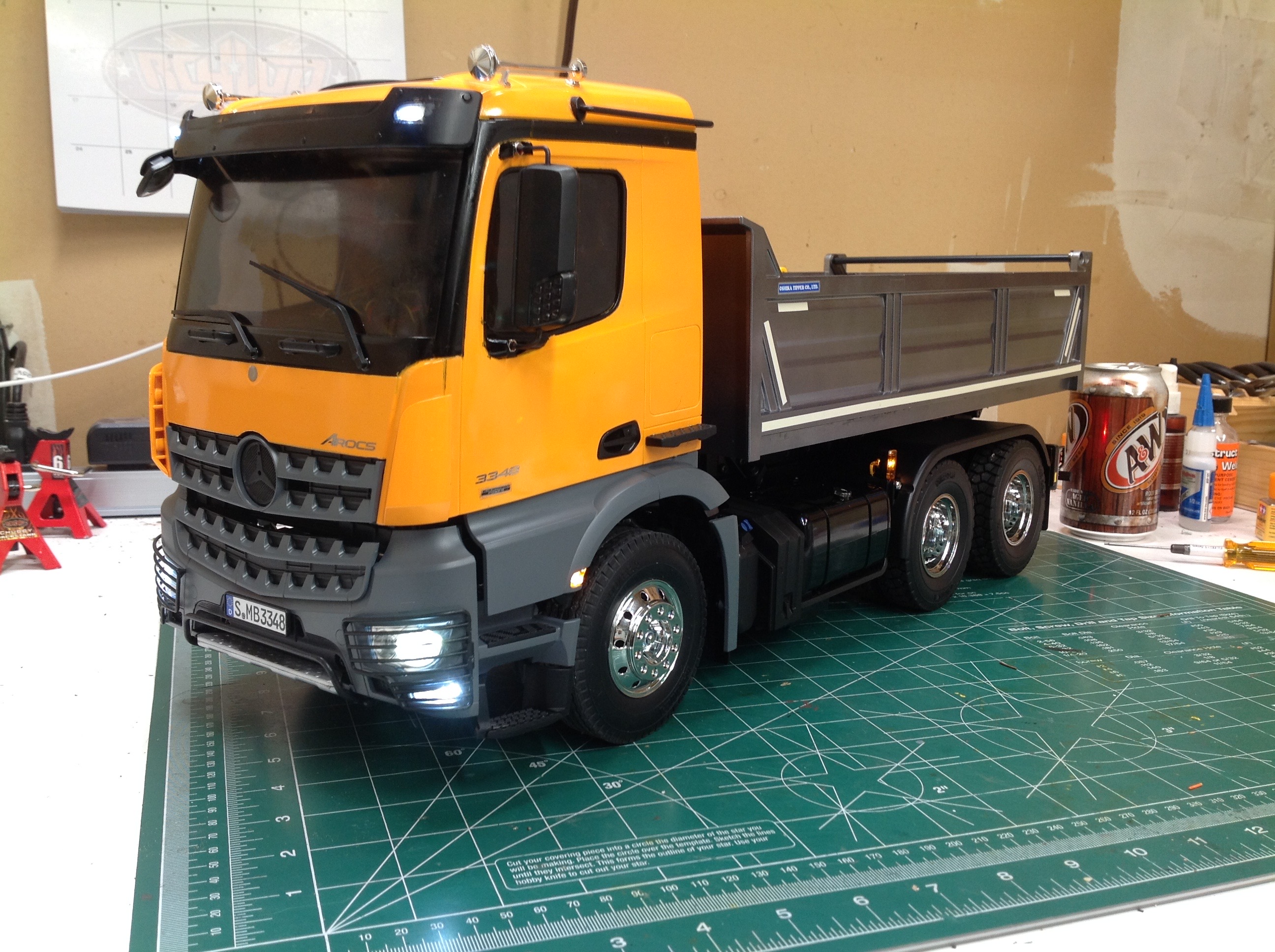
From the beginning it was a given that I would be installing the
Multi-Function Control unit MFC-03 in this model. Since I've
documented such an installation before, I won't repeat it all
here. The control of the lifting actuator takes the place of the
4th channel previously used to detach trailers and control motorized
legs. The little amber light ahead of the front wheel is not used
per the instructions. The lens does have a light bucket, but I
assume it is not used because it is too hard to get wires to this
location with all the potential interferences in the lifting cab. I
was able to solder up my own wiring to make it work.
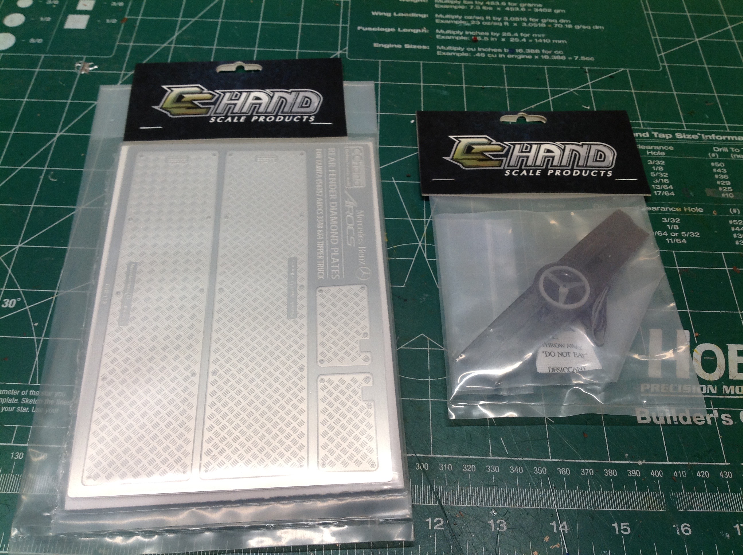
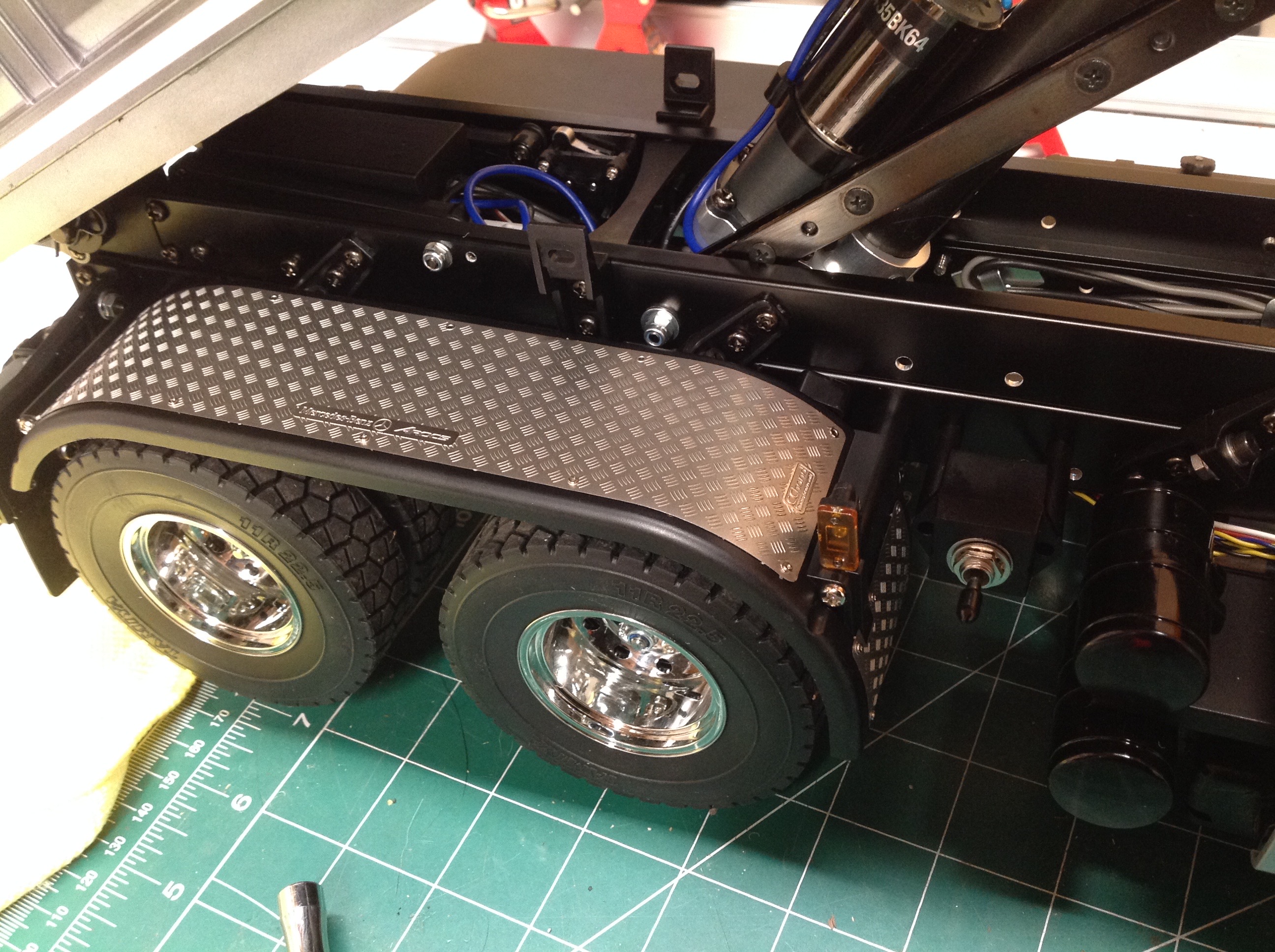
CChand makes some nice photo etched options for this truck. I
didn't really like the stickers that came with the kit to install a
diamond plate pattern on the rear fenders. I thought they looked
much too fake. These metal parts, on the other hand, actually have
a real textured diamond plate pattern and look awesome. 100x
better.
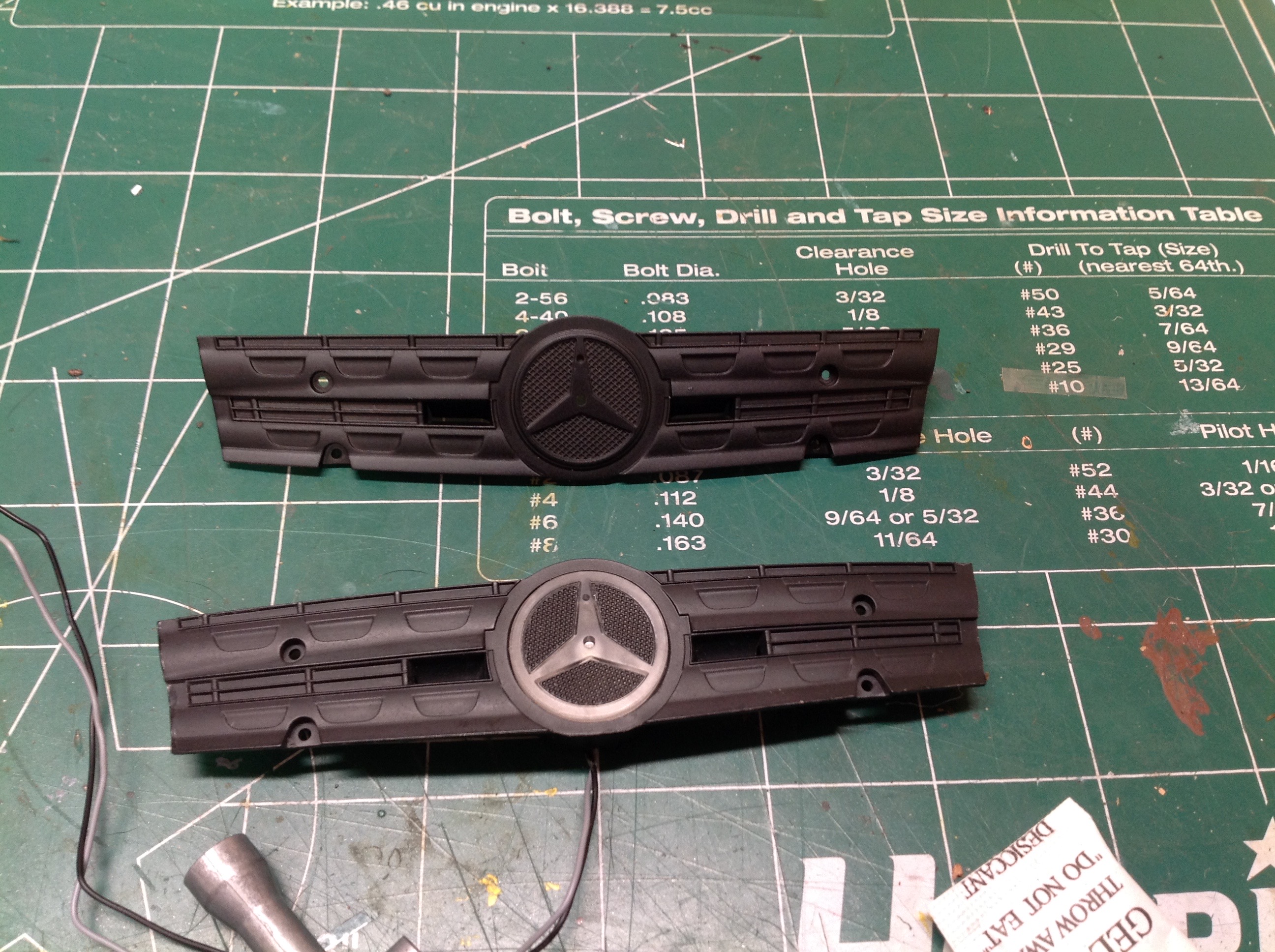
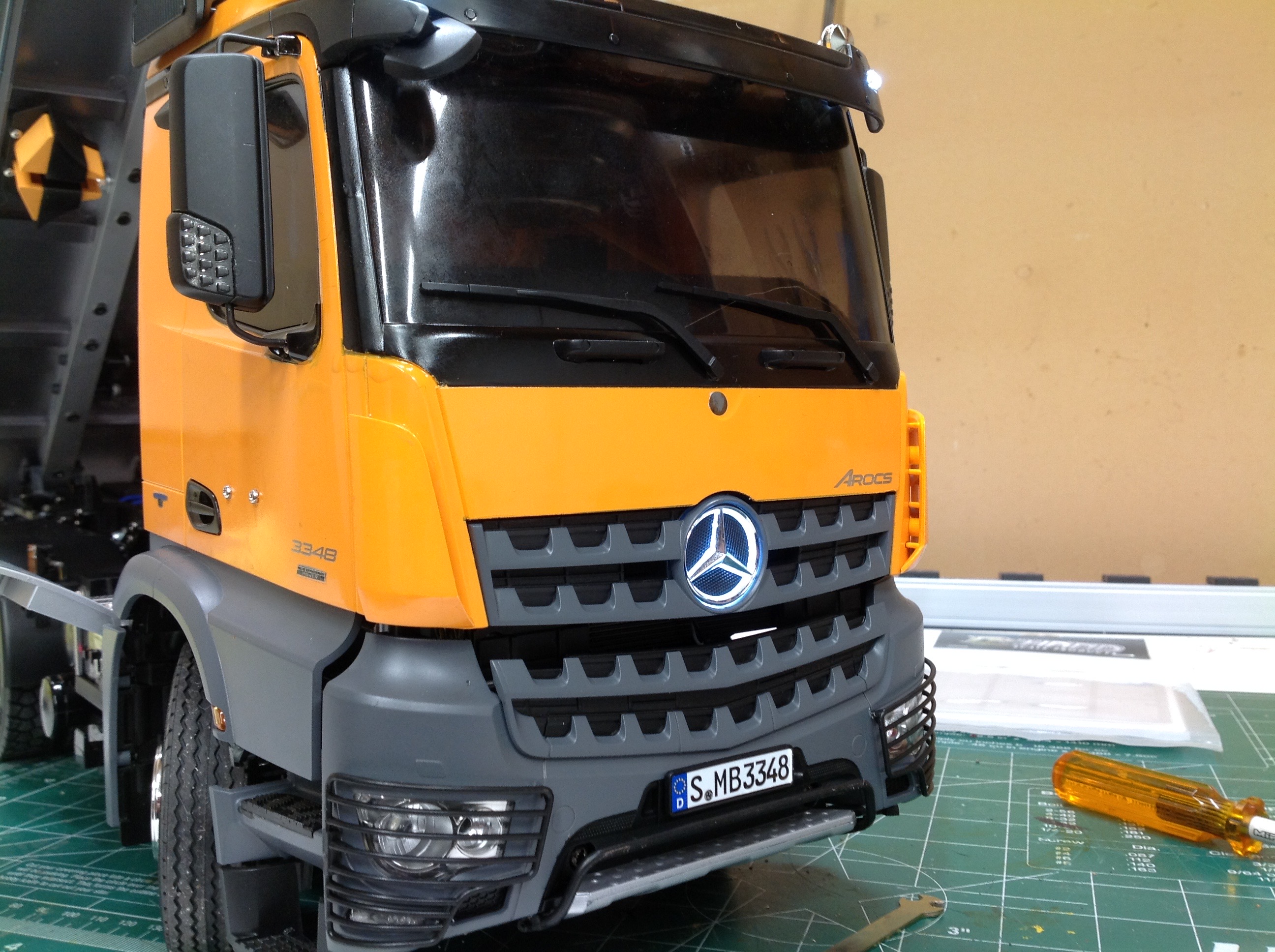
This compares the original grille center logo with the lighted version I
got. You use the same chrome emblem in either case. There
happened to be an open slot on the MFC which allowed for easy attachment
of the lit logo which comes on with the fog lights.
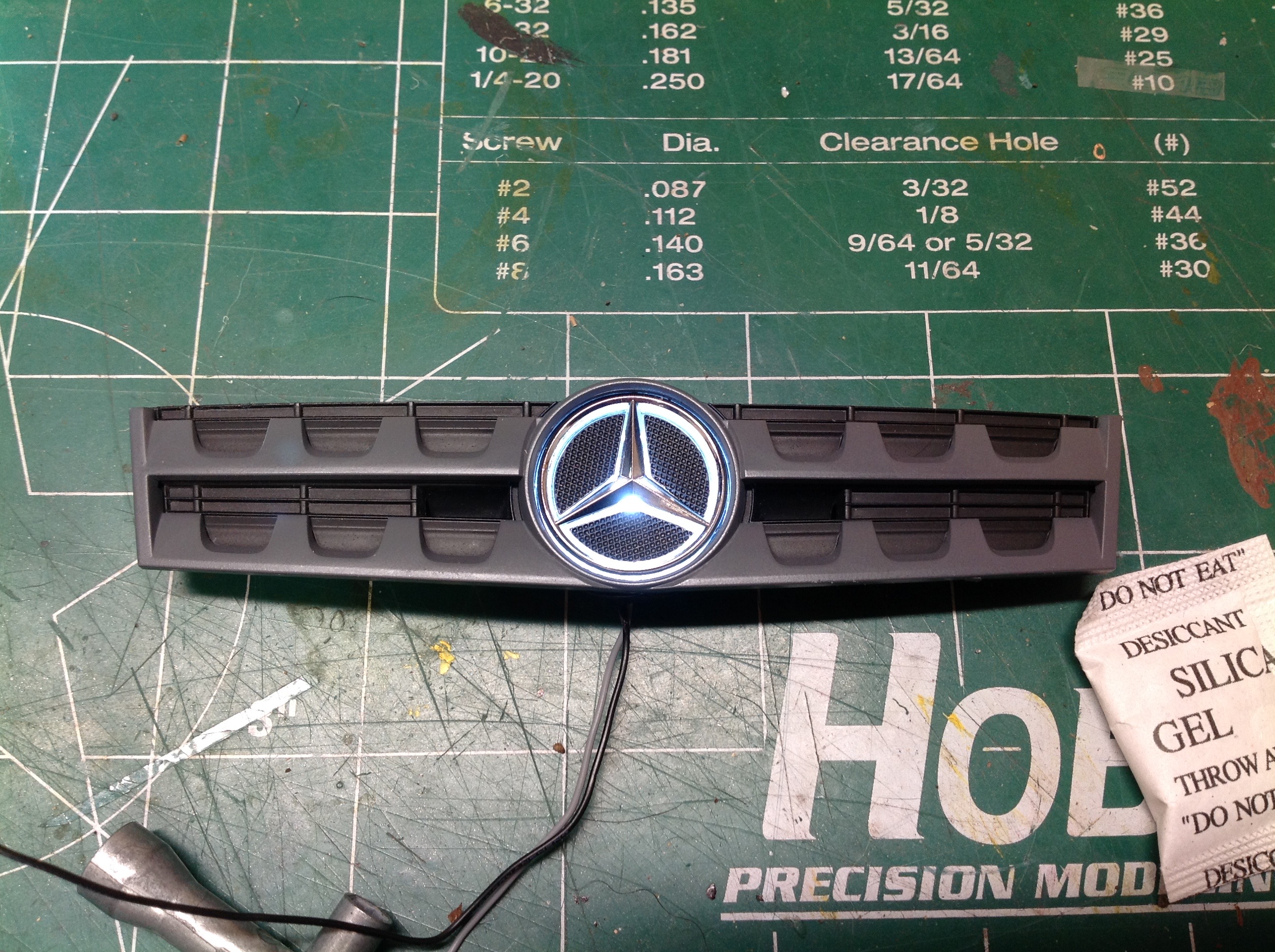
Here is the installed illuminated logo. I'm pretty sure the maker
starts with an actual Tamiya part and modifies it with the light unit
rather than making a new part from scratch. It fits perfectly,
therefore.
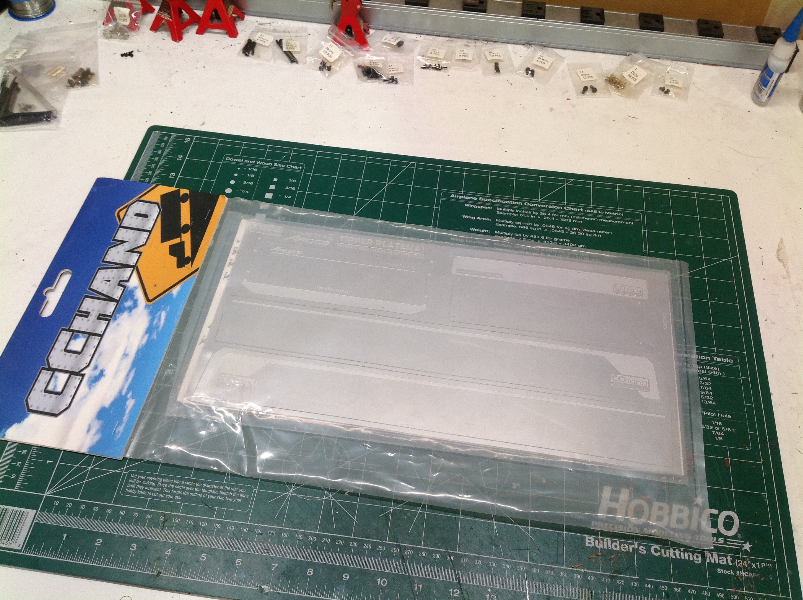
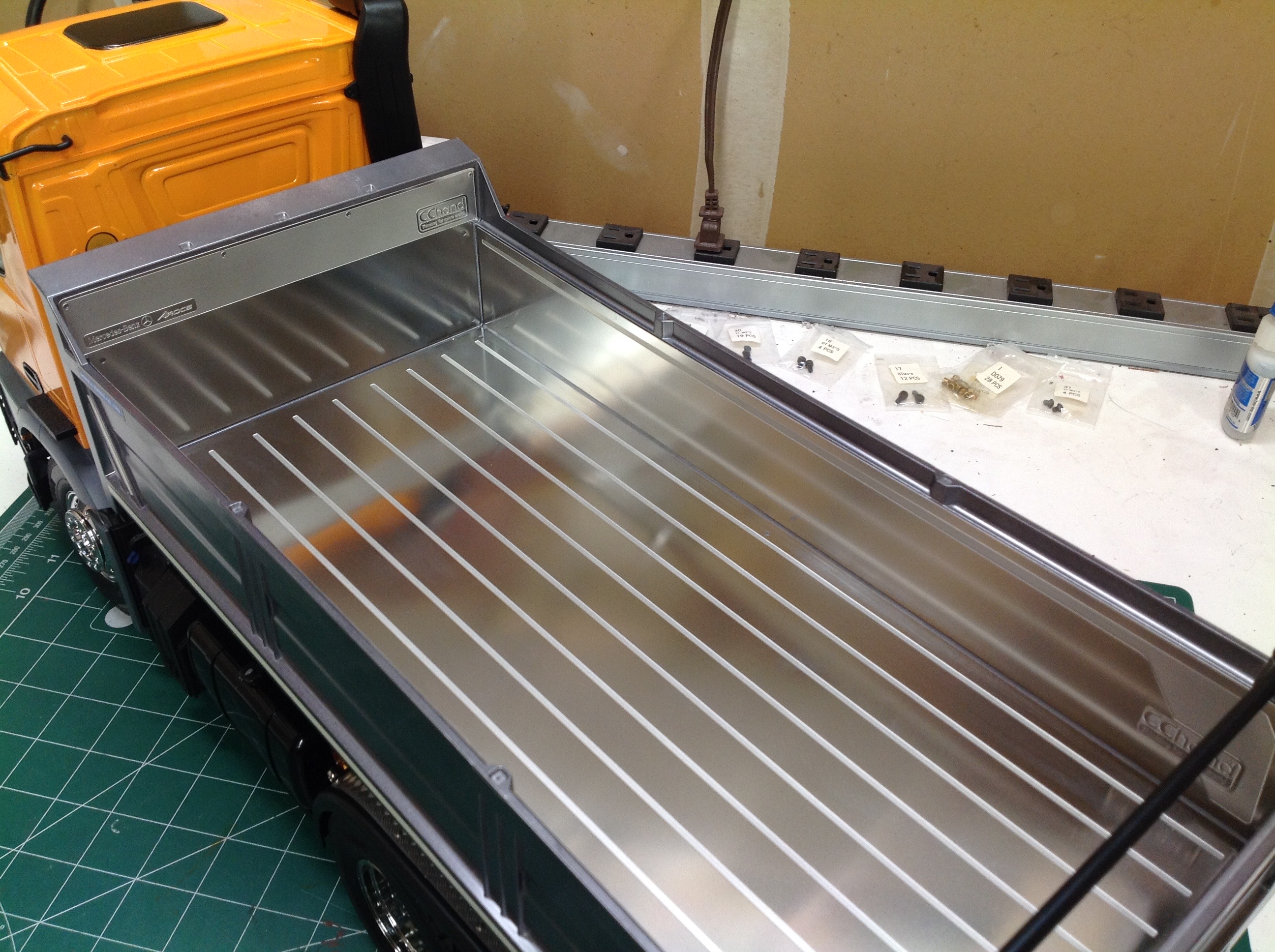
I vacillated on whether or not to buy this bed liner for a while because
it is rather expensive, but it just looks so fantastic that I couldn't
resist. It contains sheets for the bottom of the bed and all four
sides including the rear gate.
©2019 Eric Albrecht