Cross RC UC6 Project
Page 2: Building the Chassis
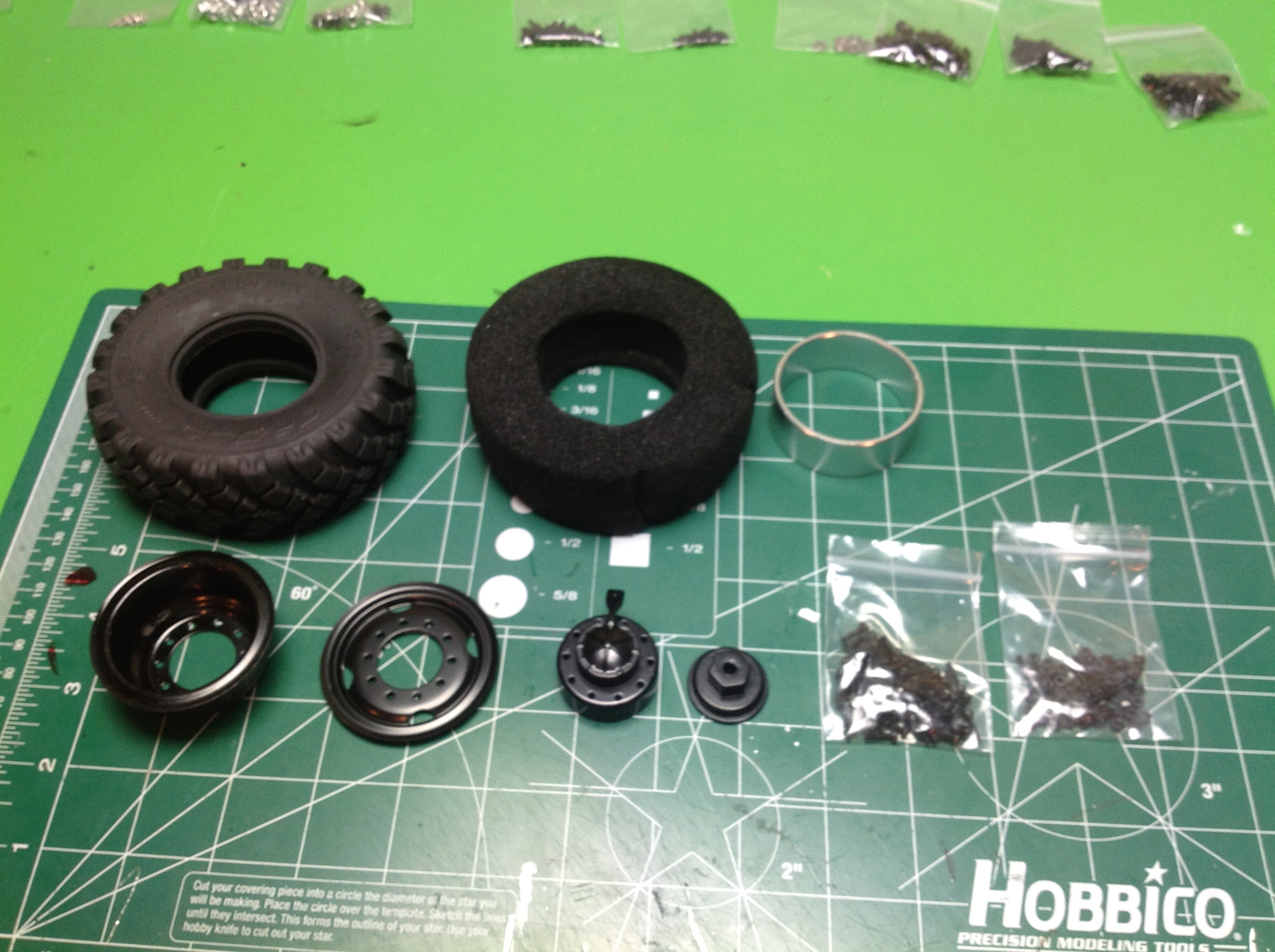
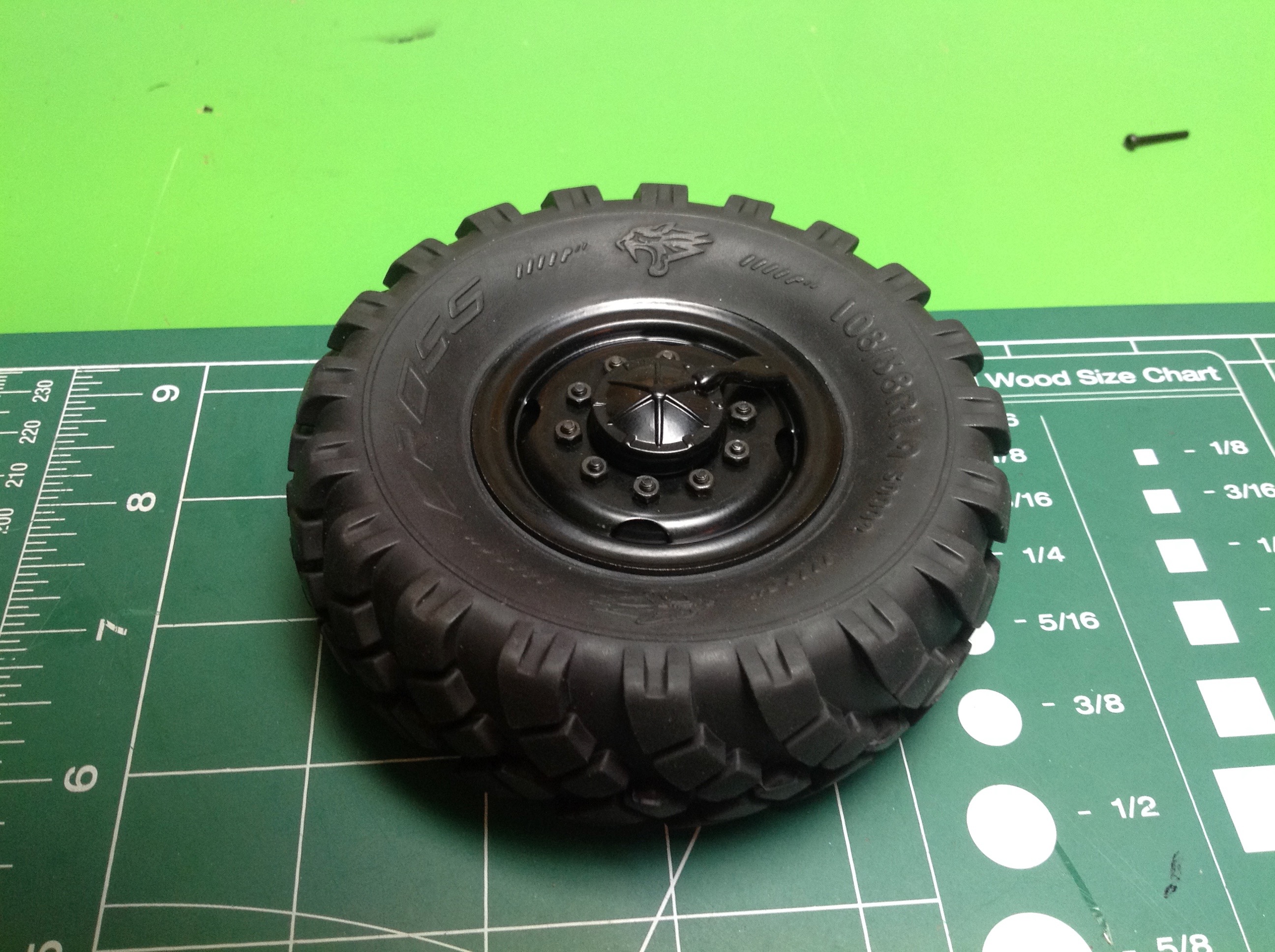
The very first thing I did was to assemble the wheels and tires which
involves a lot more parts than you might think. Each steel
beadlock wheel has a front and back with a center ring, then there is
also a cast hub in front and back, and finally there is a hub cover
which represents the remote pressurization system on the real
thing. 6 wheels have this full setup, which the 7th spare has just
a plastic wheel but a standard tire. The tires are nice and
sturdy with an internal open cell foam.
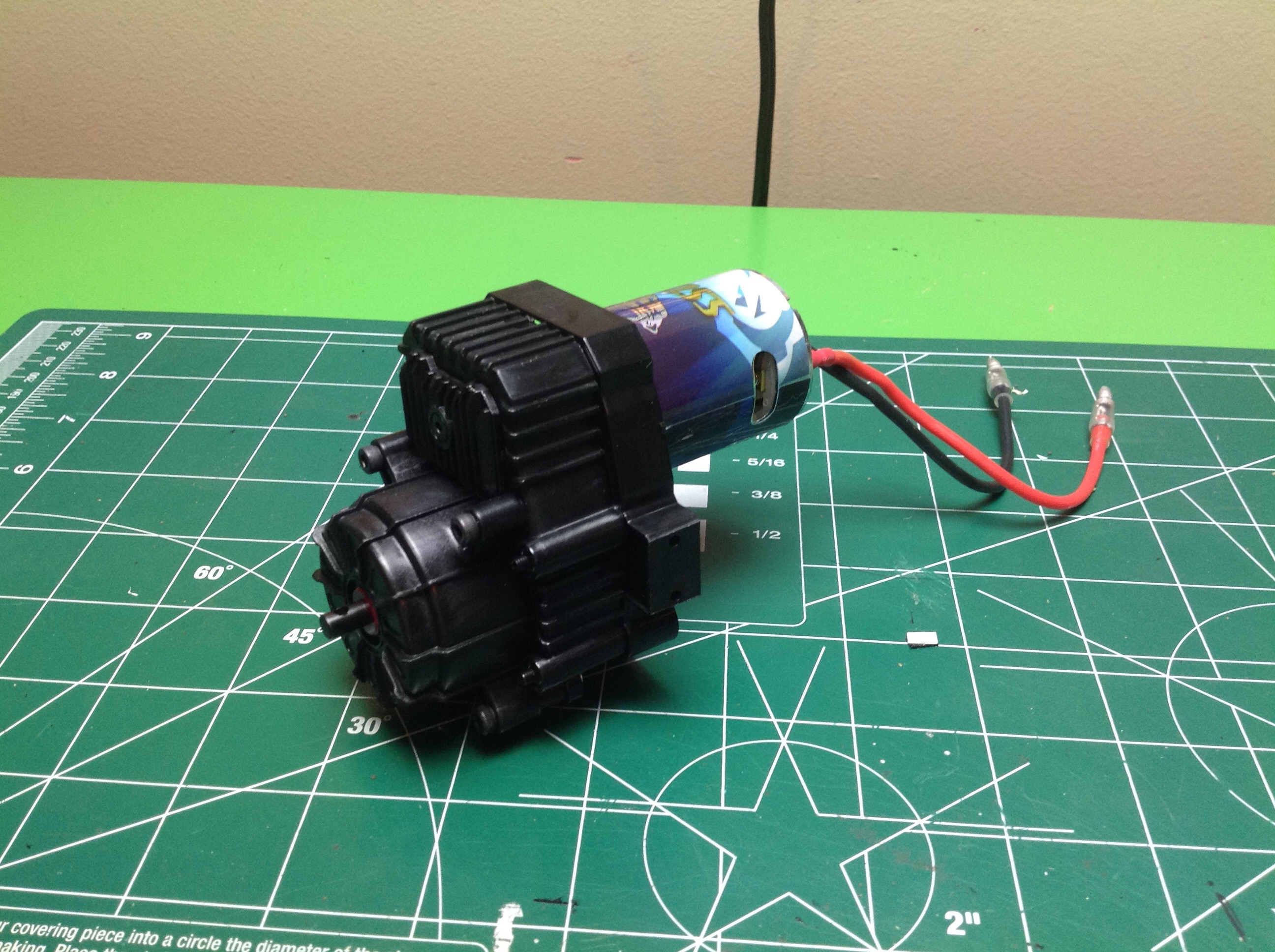
The gearbox actually came pre-assembled, but that didn't stop me from
tearing it apart to see what was inside. We have a nice planetary
reduction set with an aluminum carrier hub. The gears are all
metal (except the spur) and there are bearings on everything. The kit came with a 35
turn brushed motor which has been excellent so far. You can also
see the large aluminum motor mounting plate.
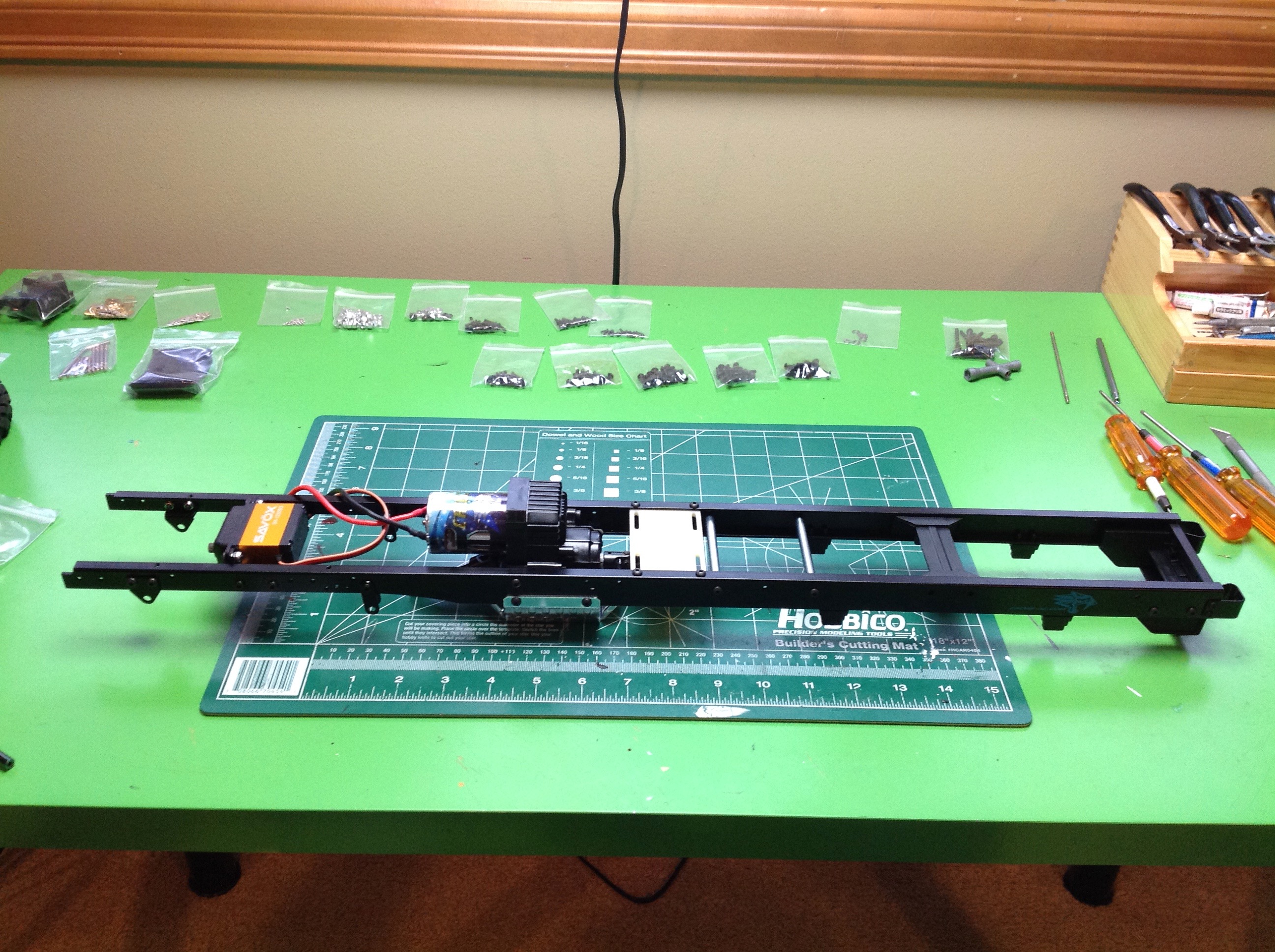
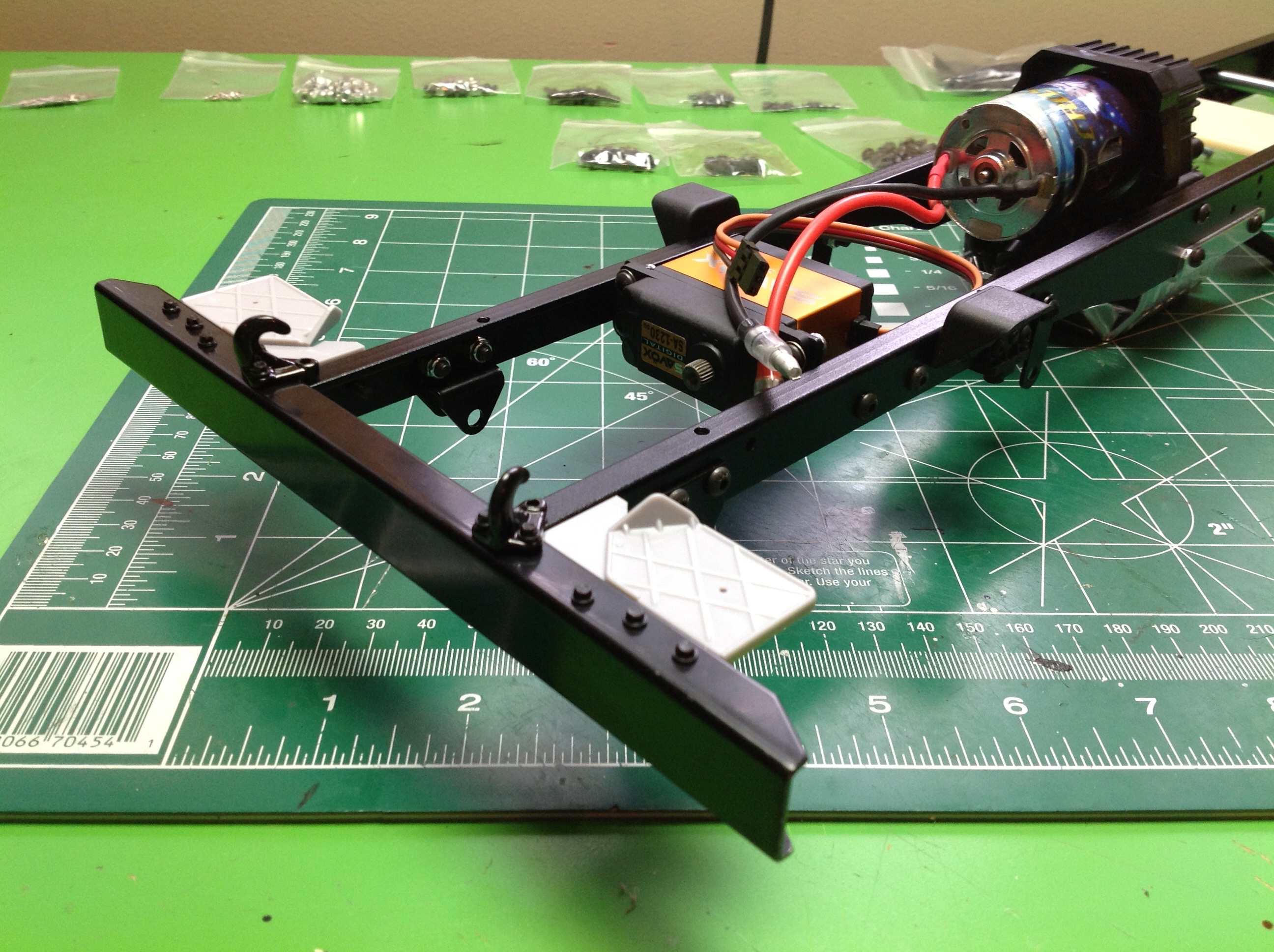
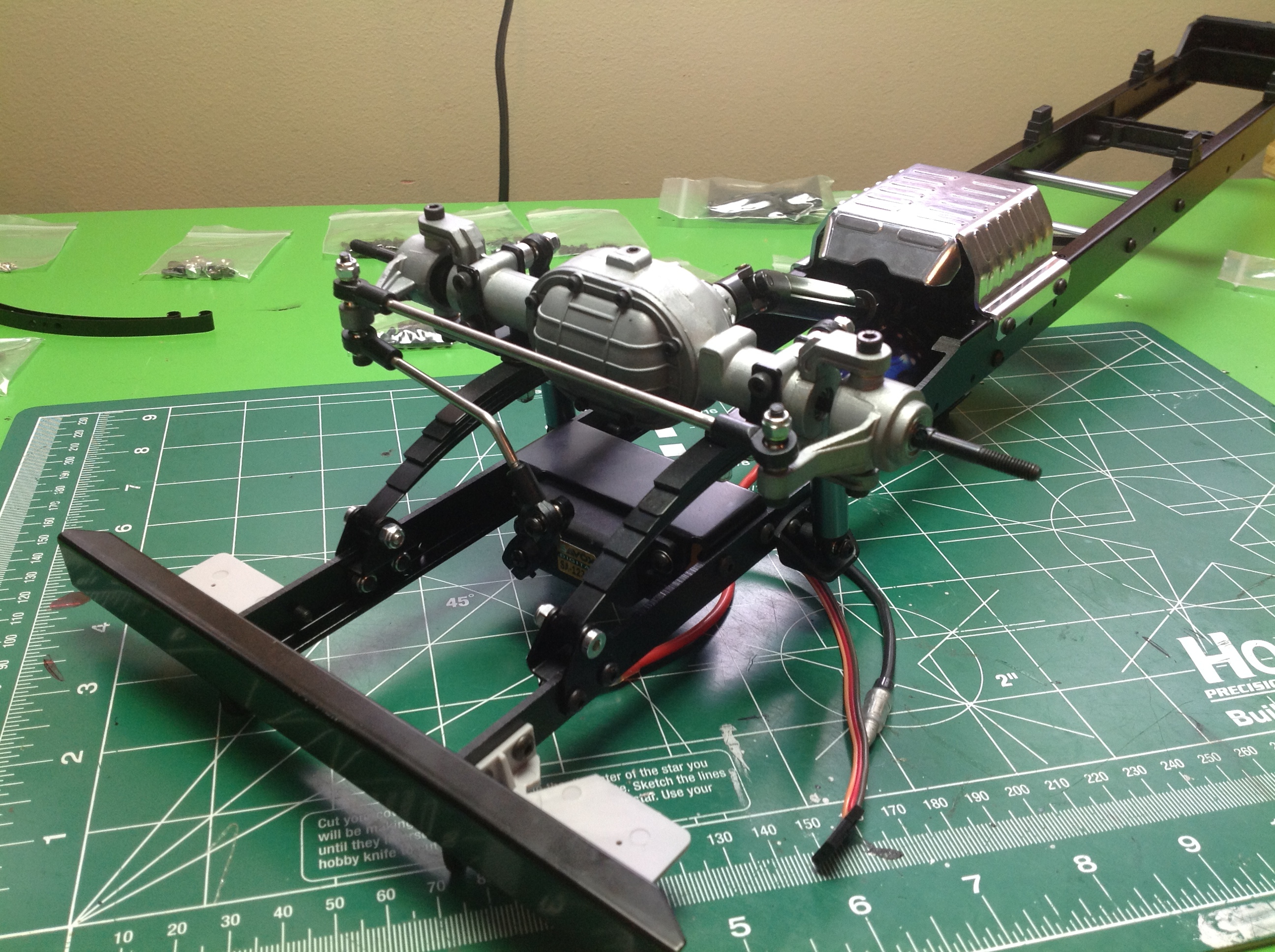
Now we'll start work on the ladder frame chassis. The frame rails
are long, straight, steel C-channels. There are a series of
intercostals including the one that supports the steering servo. I
chose a high torque Savox servo, though it is not waterproof. The
most significantly structural cross member is the transmission itself
which sits just forward of center. The front bumper attaches next
and is also steel. It even comes with scale hex bolts which are
installed using an included tiny driving tool.
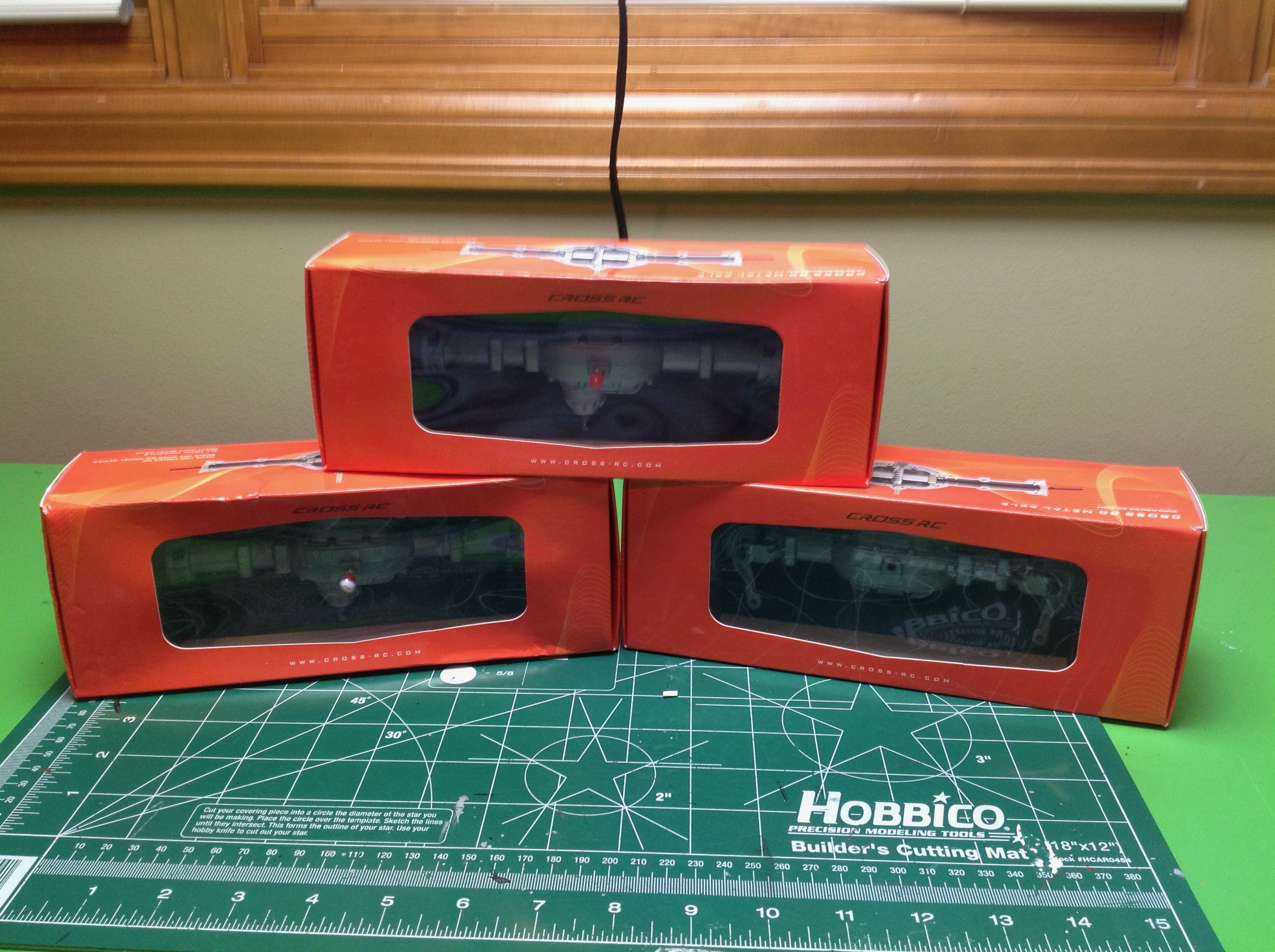
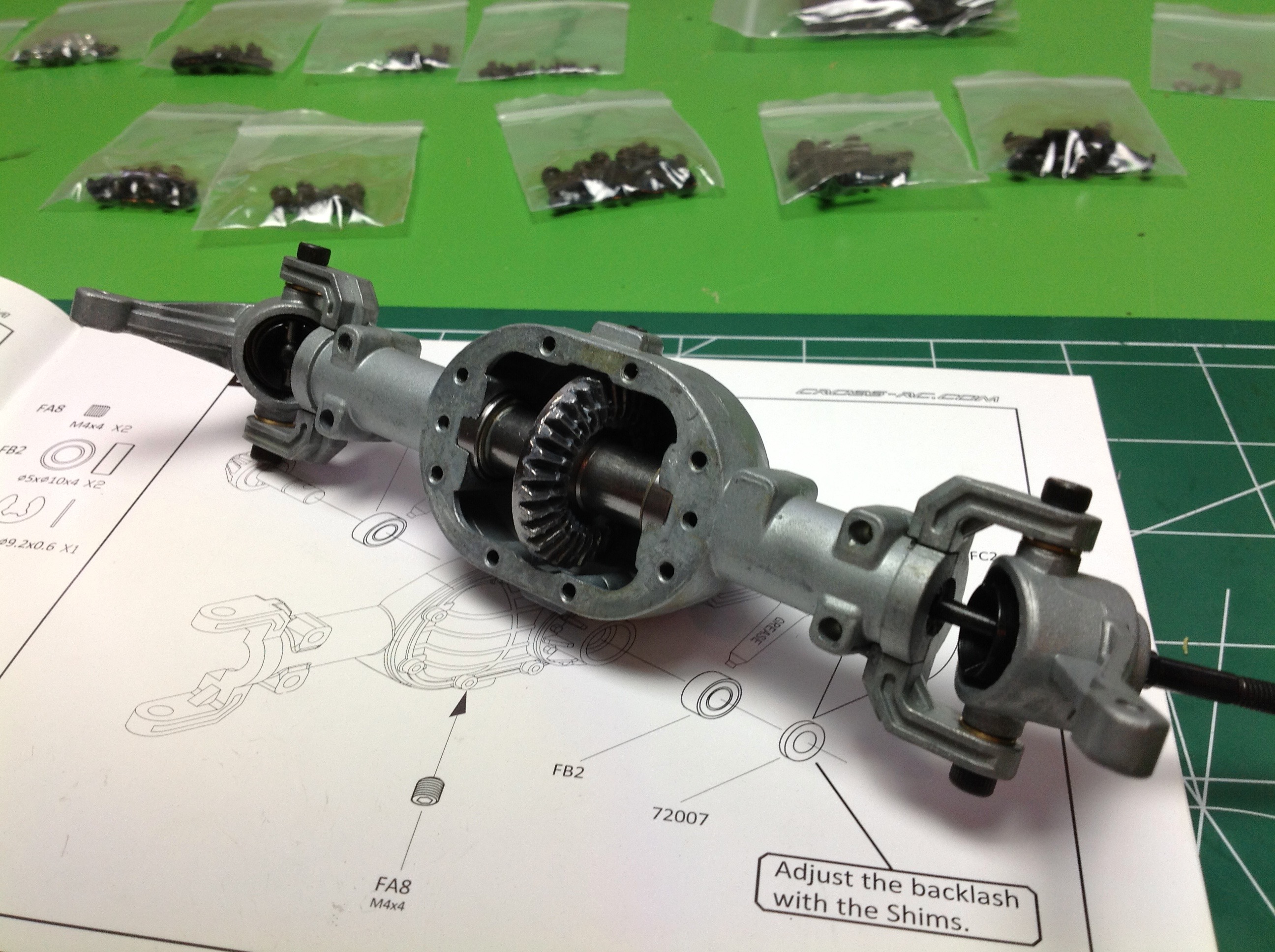
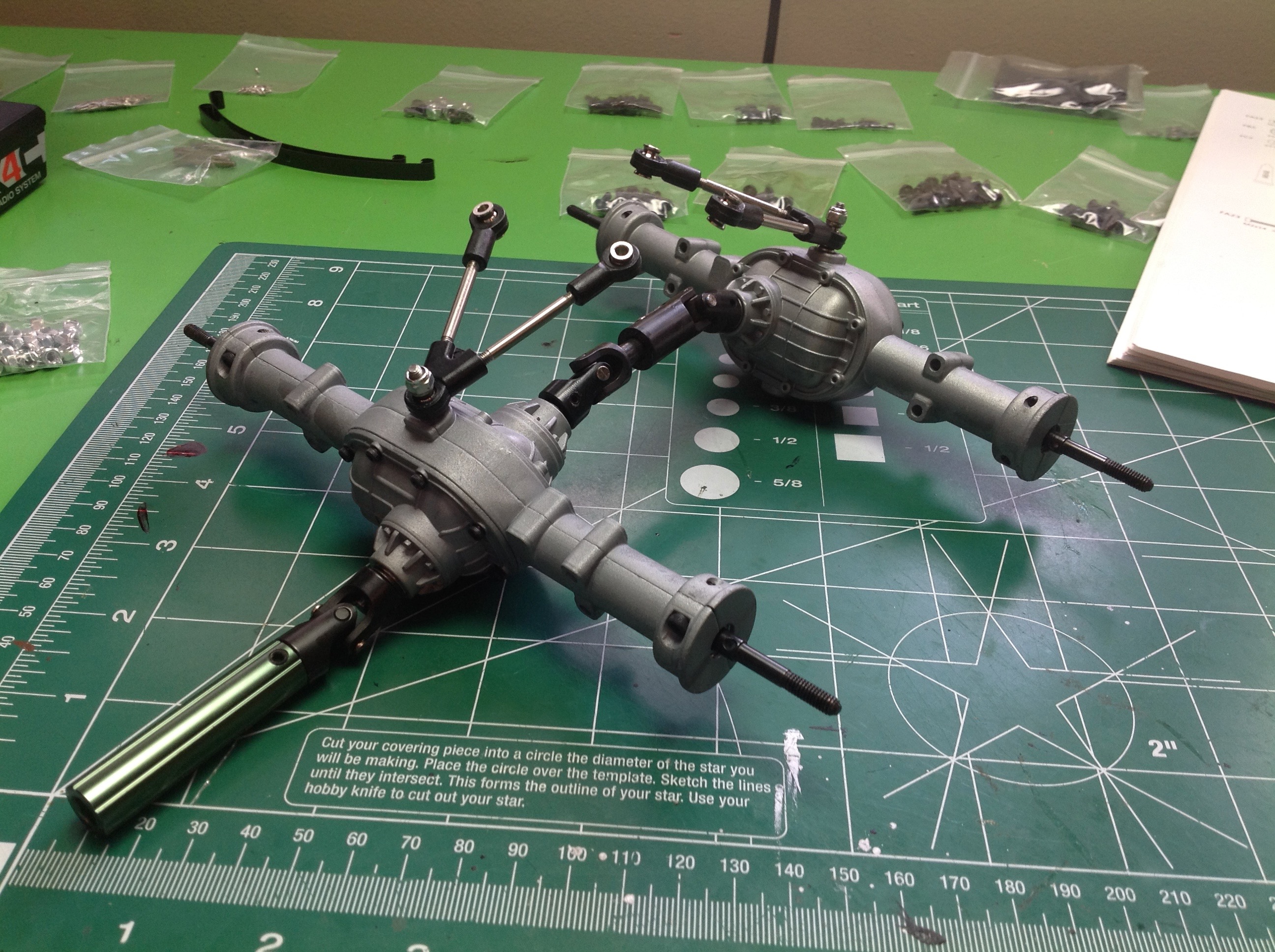
The three metal solid axles also come pre-assembled, and each is
different. The front axle steers, the middle axle has both an
input and an output, and the rear is a standard solid axle. I
opened up the front differential housing to make sure everything was
well lubricated, which it was.
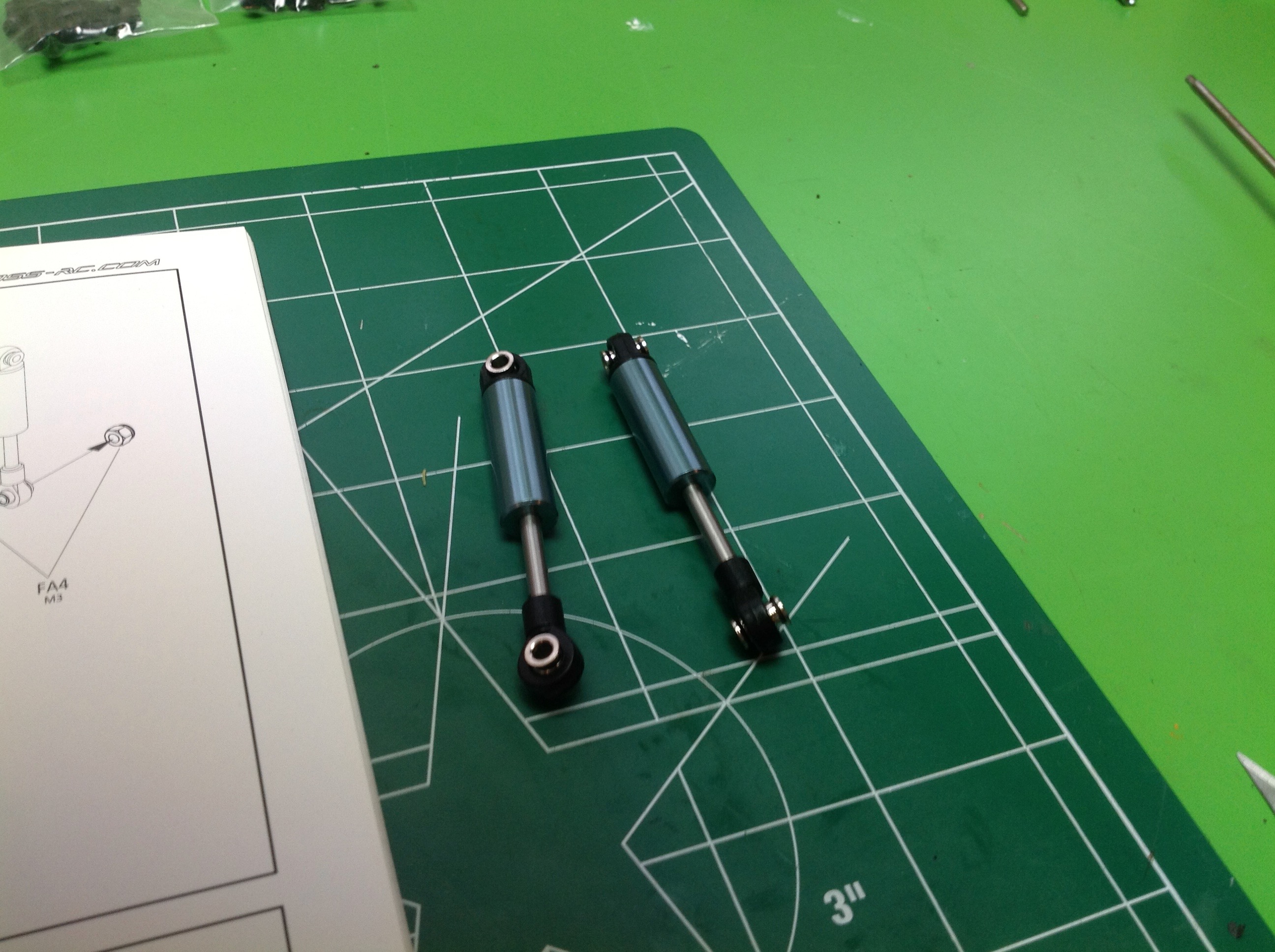
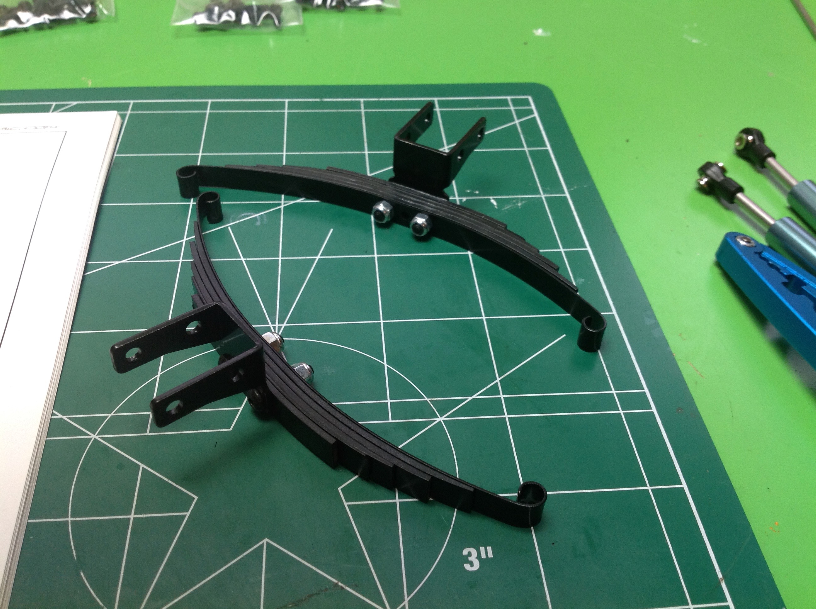
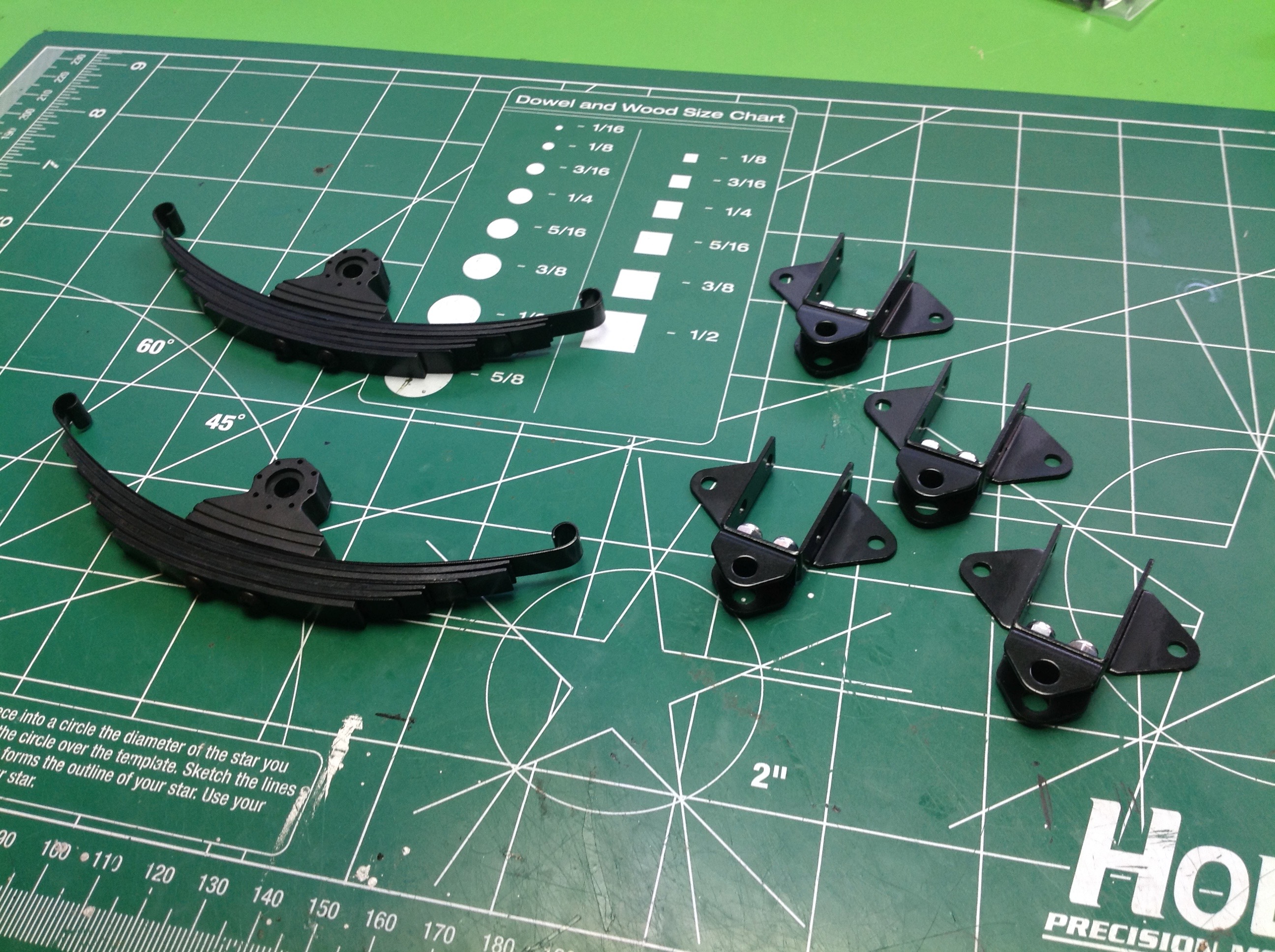
The shocks are also pre-assembled. These are really only for
appearance since they don't offer any significant damping. There
is a small spring inside to extend them. The cylinders are real
aluminum despite the lack of function. The real support comes the
big stack of leaf springs, but the stack isn't as big as it looks.
This many leaves would result in a suspension which is far too stiff,
yet it is the correct number for scale. Cross manages this by
making half of the leaves plastic just for appearance, and the remaining
steel for support.
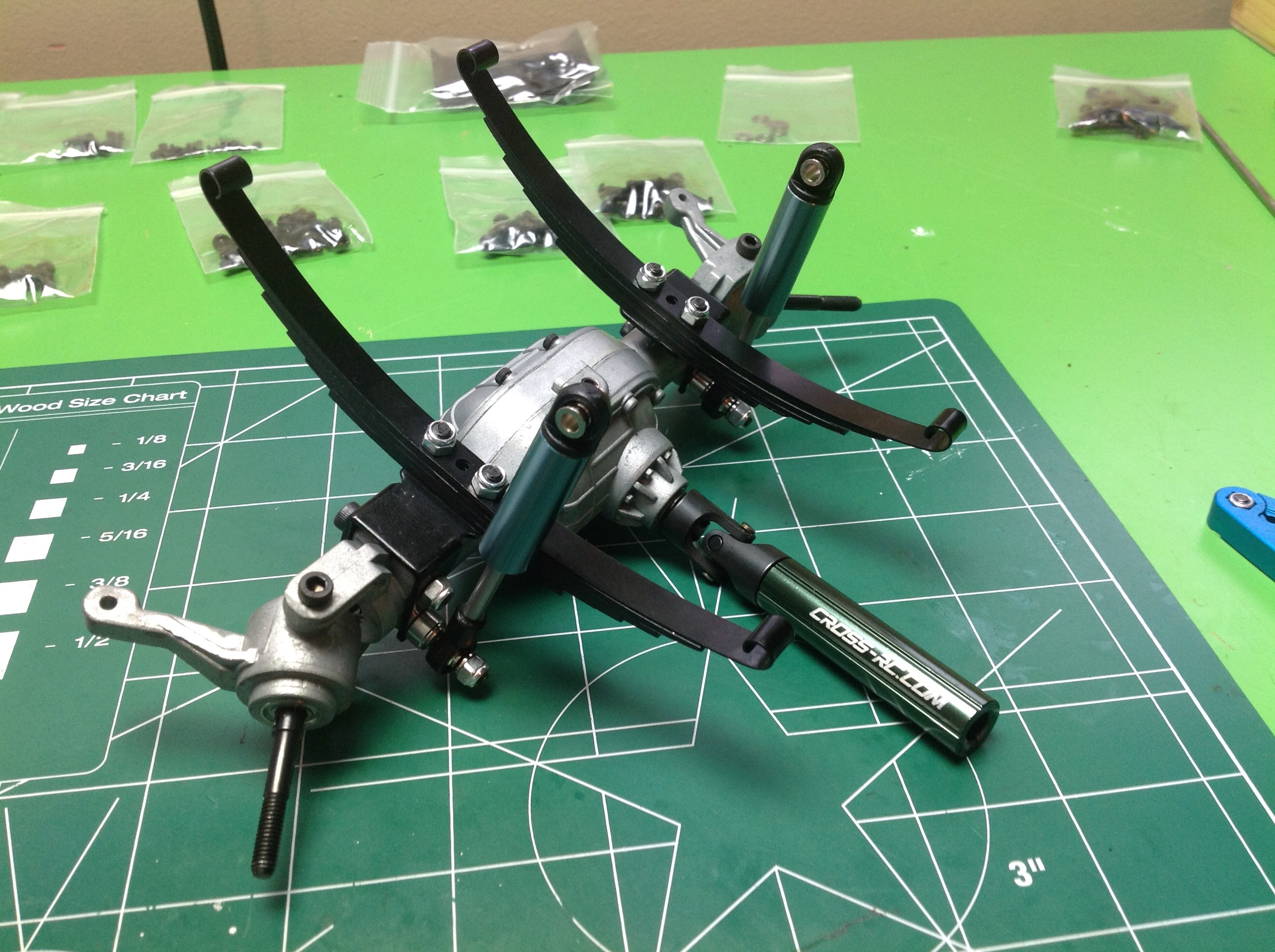
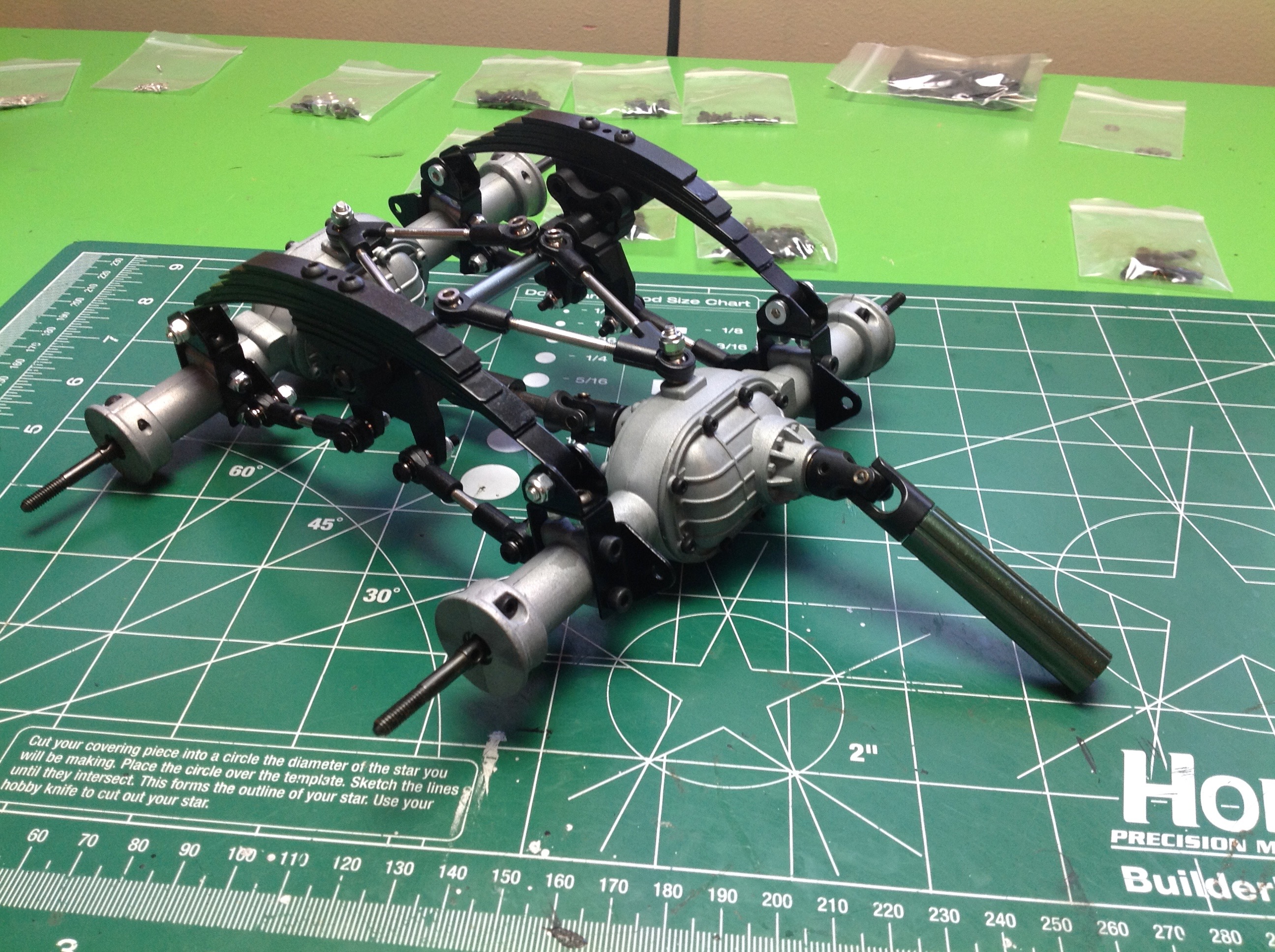
Here's the completed front suspension assembly. The leaf springs
and shocks attach to the axle with brackets, then the whole thing is
hung from the frame on shackles. The servo is a direct drive
connection to the steering hub with no servo saver. This is a
sturdy setup. You can also see the lovely metal front universal
drive shaft and the skid plate which is now installed beneath the
gearbox.
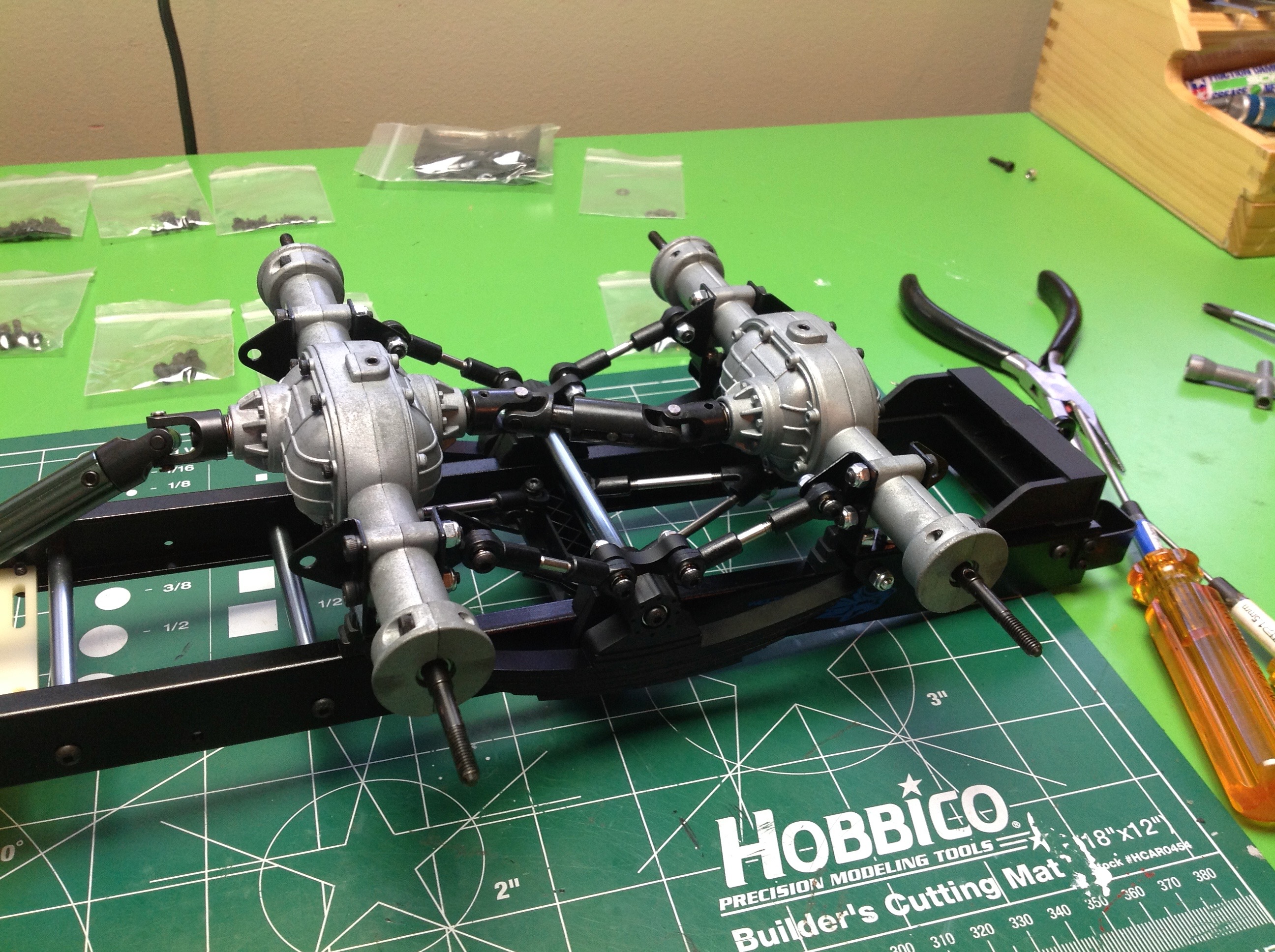
The assembly of the rear suspension is similar. A set of V-shaped links provides lateral and rotational support.
The twin rear axles share a common set of leaf springs while a set of
radius arms controls the angle. This setup serves somewhat like a
sway bar in that upward motion of one axle must be balanced by the
other.
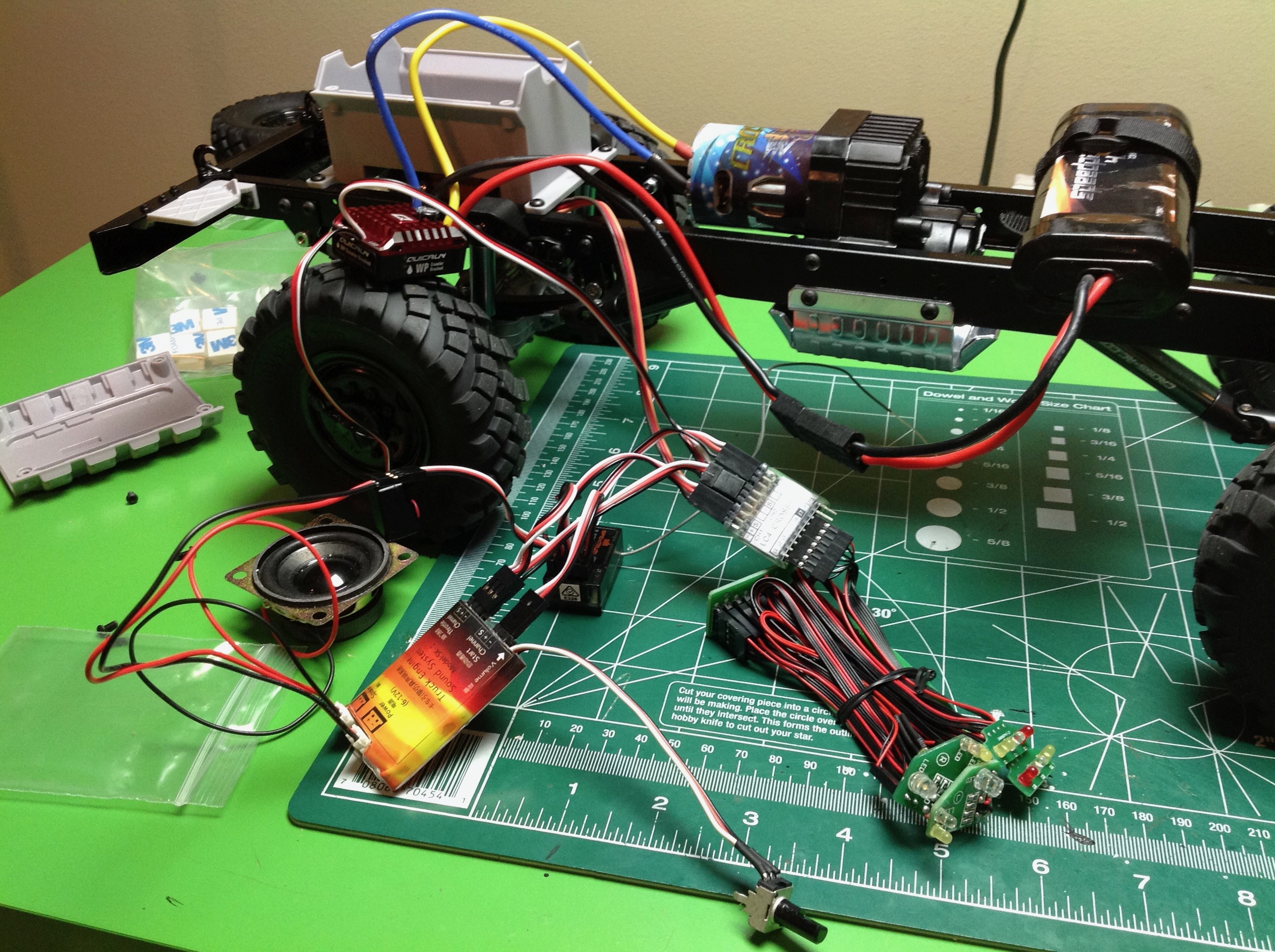
The chassis is done except for the wiring, and that is no small
task. There is a box up front which looks like an engine and
serves to hold the electronics. In this case we have a receiver (4
channel), an ESC, a light controller, a sound controller, and all the
associated wiring. Both the light and sound controller need
transmitter input, so this means the steering and throttle need to be
run in series through both devices. At this point I have wired it
all together just to confirm I know what I'm doing and that it all
works. The 3rd channel is used to turn the headlights on and off
and the 4th to honk the horn. The model will work with only two
channels if desired.
©2018 Eric Albrecht