XRay XB4 Project
Page 1: Chassis Construction
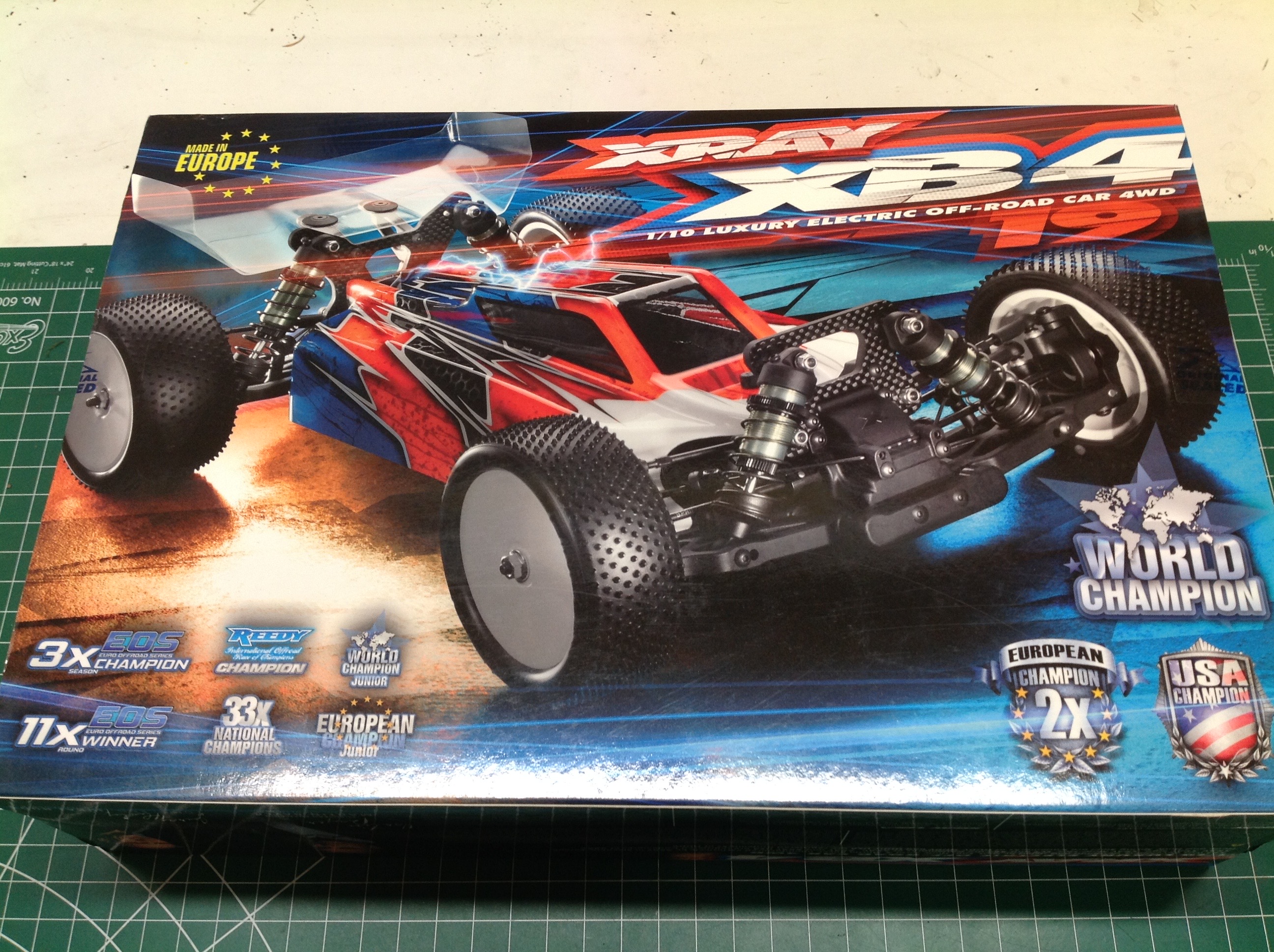
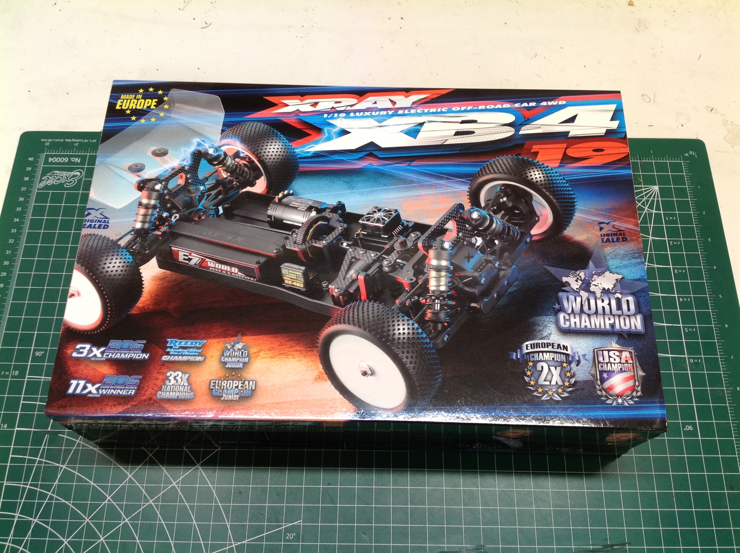
The box was a lot smaller than I expected but it sure is colorful.
All 6 sides are printed in glossy full color. The front shows the
completed buggy while the back shows only the chassis.
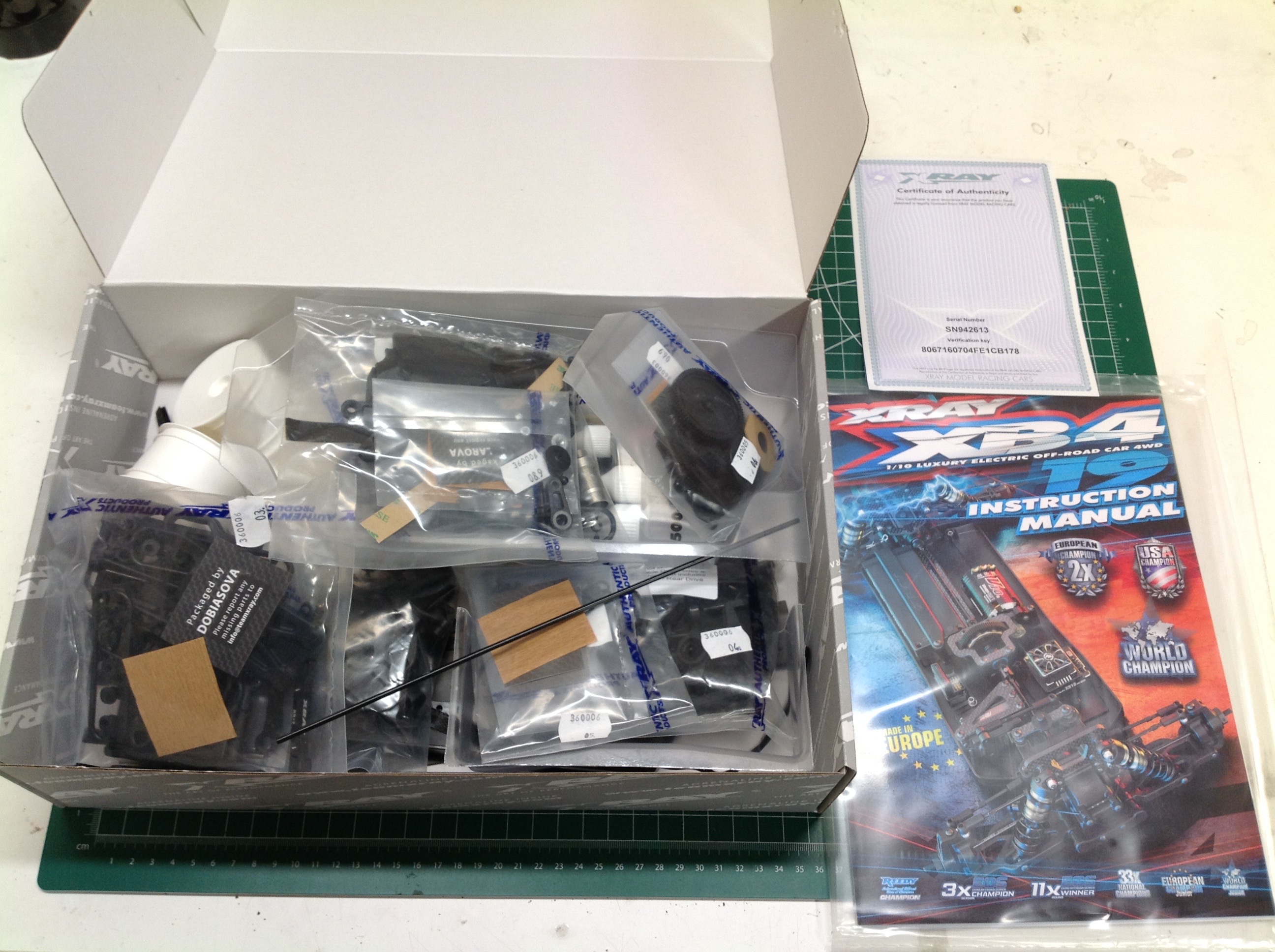
Upon opening the box we can see that the parts and hardware for each
step are bagged individually. Not only is the cover of the
manually in glossy full color, the whole book is in color. The
colors are used for a specific purpose. There is color coded
exploded view at the beginning of each step. parts labelled in
their natural color are found in the bag for that step, parts labelled
in pink are found elsewhere in the box, and parts labelled in blue are
from a previous step. The color of the part itself also means
something. Plastic parts are shown in black, driveline parts are
shown in pink, bearings are shown in cyan, hardware is shown in blue,
and miscellaneous mechanical parts are shown in light blue. Every
exploded view also shows a list of optional parts which are available
for that assembly. Every single step has multiple options
available. Each step is then divided into a number of substeps
which show how to assemble the parts in the exploded view in more
detail. The back of the manual has a setup sheet, a huge exploded
view of the entire buggy, and a complete parts list. The kit even includes a certificate of authenticity.
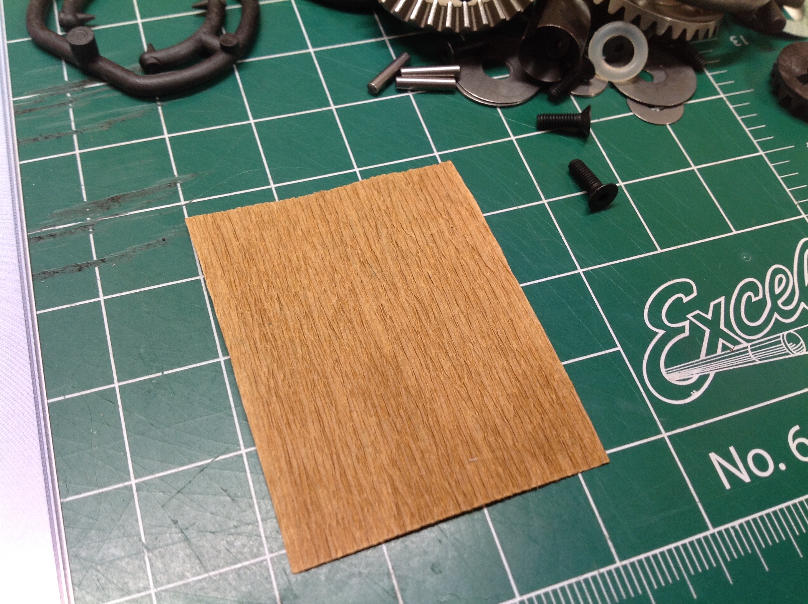
The internal packaging of this model is quite unusual. Each part
bag include a little bit of brown paper that looks like wood
grain. Presumably this is a desiccant to absorb moisture.
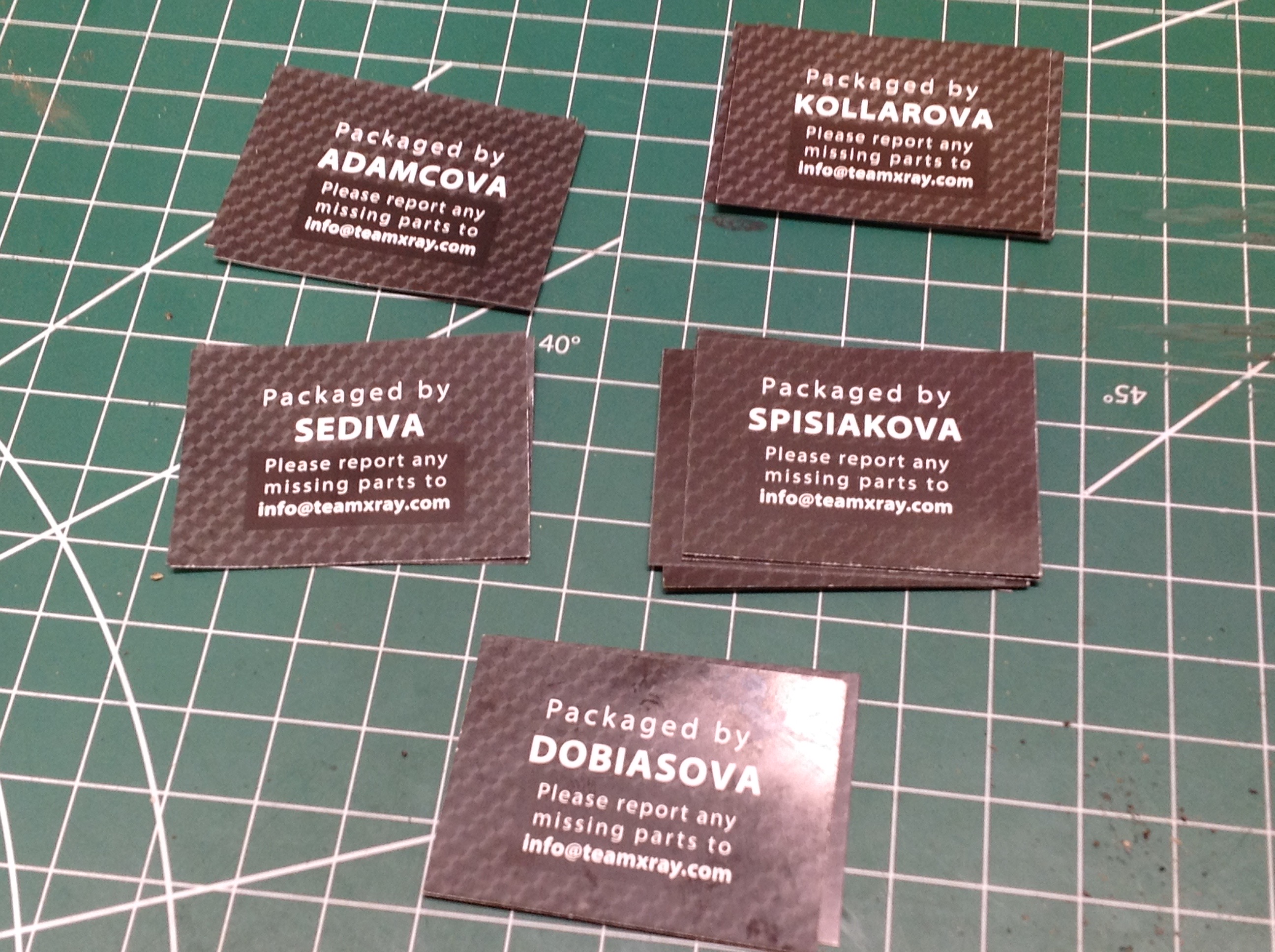
Each bag also comes with a slip of paper which indicates who packed and
inspected the bag. I found 5 different inspectors worked on my
kit. Sposiakova seems to have been the most busy.
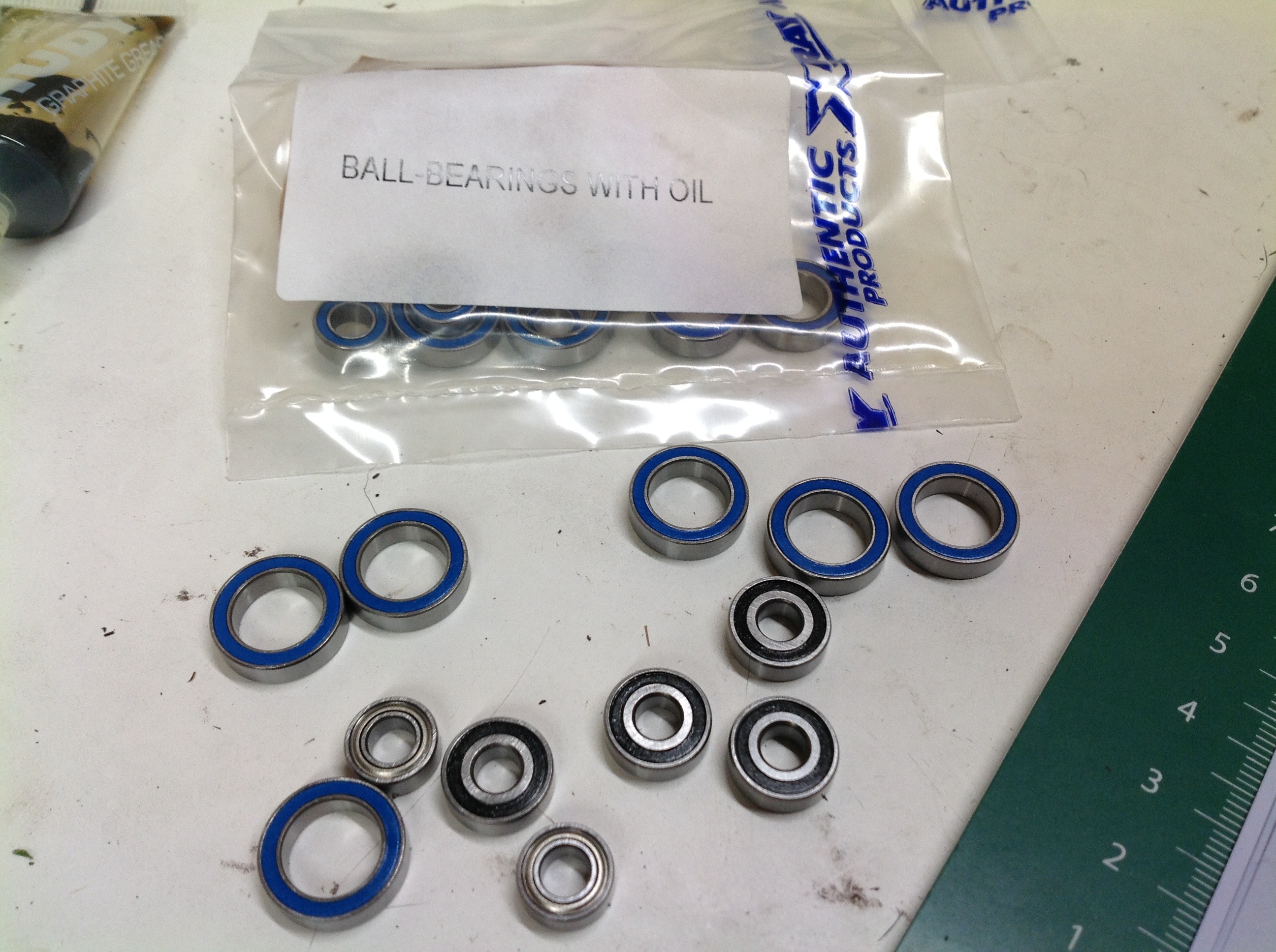
The bearings come separated into two parts. Some of the bearings
are in a different bag labelled as "with oil", presumably
lubricated. However, the manual says nothing about which bearing
to use in which step except by size. If the same size is available
in both forms, there is no sure way to know which to use.
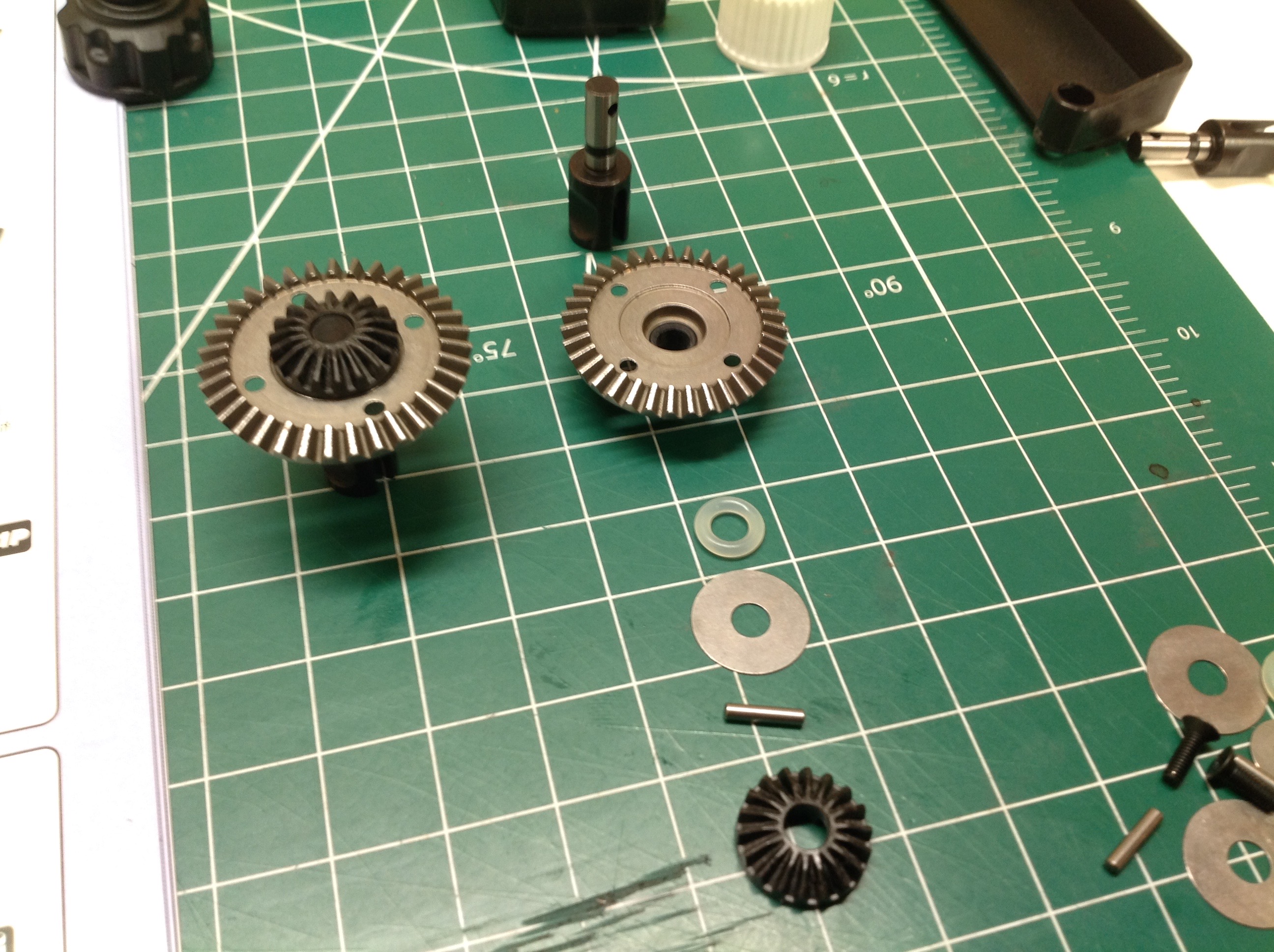
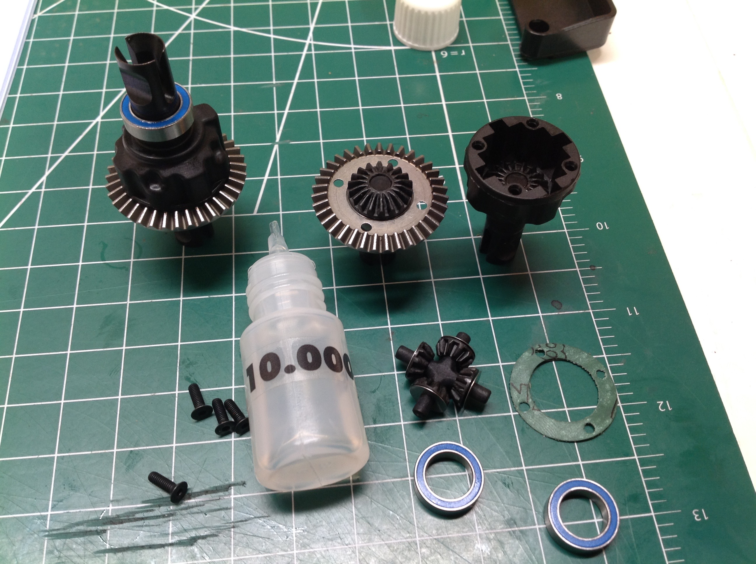
I was surprised to see that the spider gears in the differential are
plastic. Like the other plastic parts in the kit, they seem to be
carbon filled and are very strong. This is a sealed differential
filled with 10,000 cSt viscosity silicone oil. The front and rear
diffs are mechanically the same and use the same oil by default.
The oil viscosity can be changed to accommodate different traction
conditions.
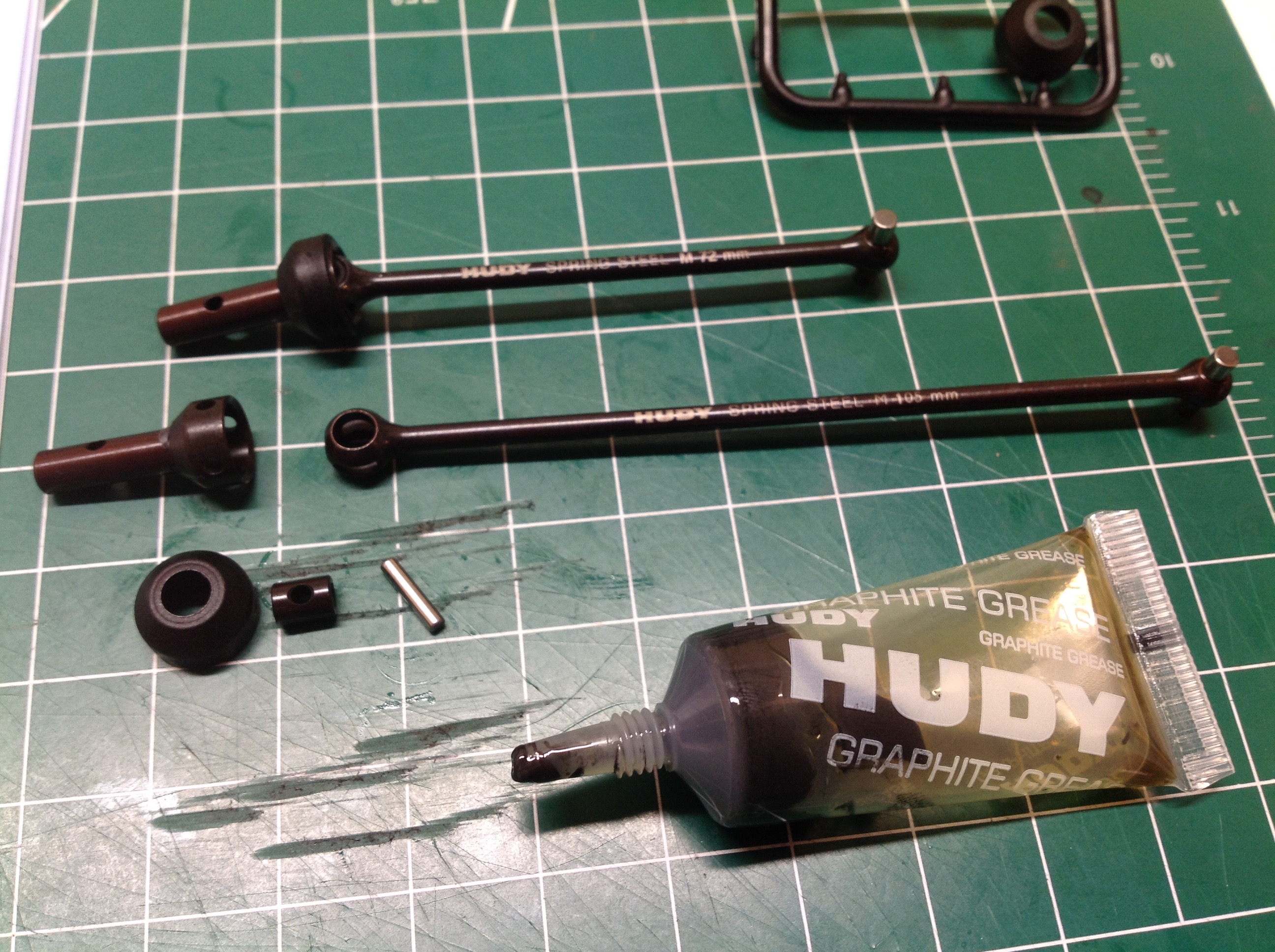
XRay is very proud of their materials including the "spring steel" used
for the CVD drive shafts. I'd be interested to know what alloy it
actually is. Spring steels are not particularly high strength but
they are resilient. The shafts are very thin which makes for low
rotational inertia allowing rapid changes in speed. The tiny tube
of Hudy grease which comes with the kit must be used very sparingly if
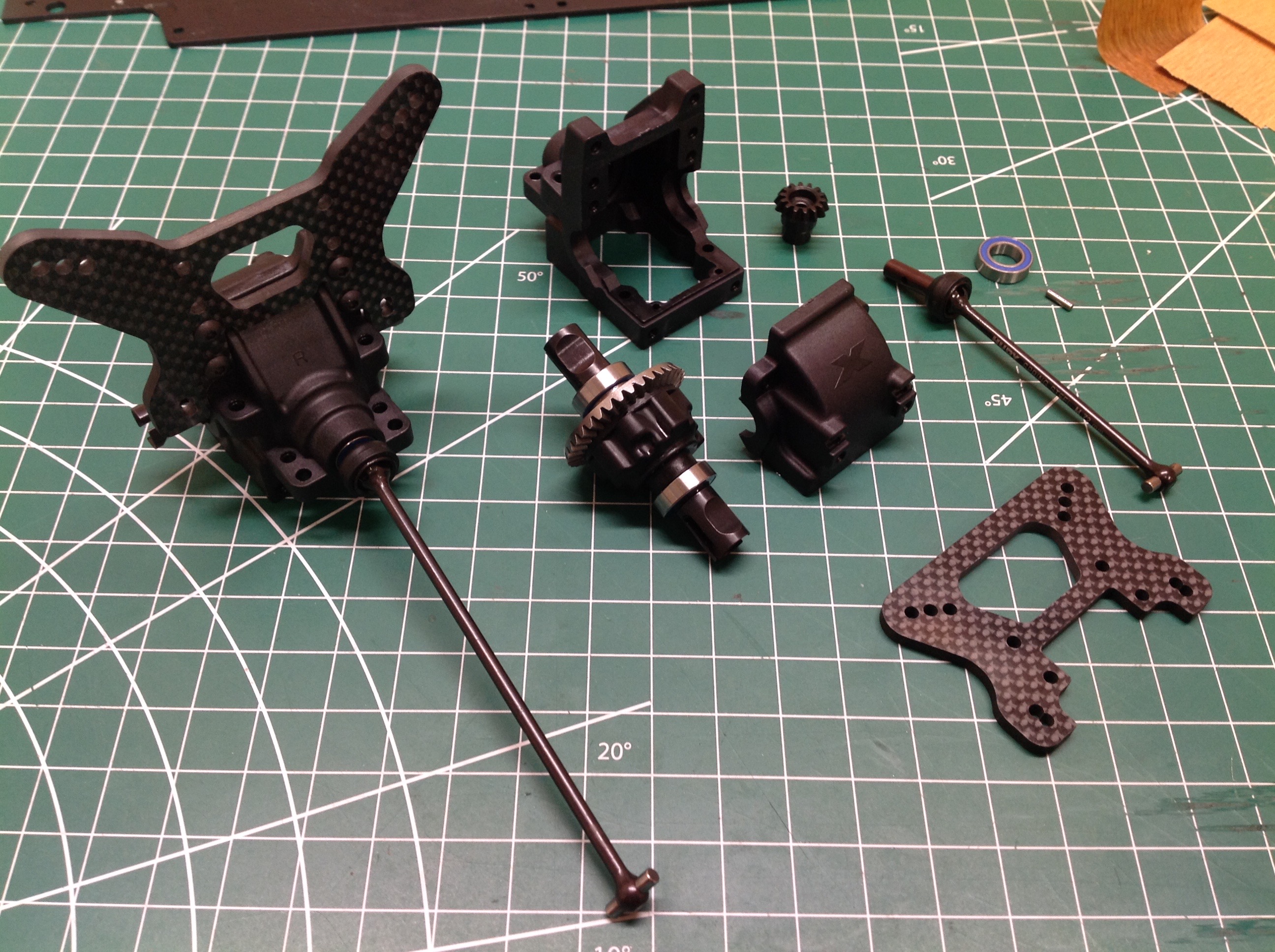
it is to last through the build. The front and rear bulkheads are
identical, but the drive shafts are different lengths and the carbon
fiber shock towers are shaped differently.
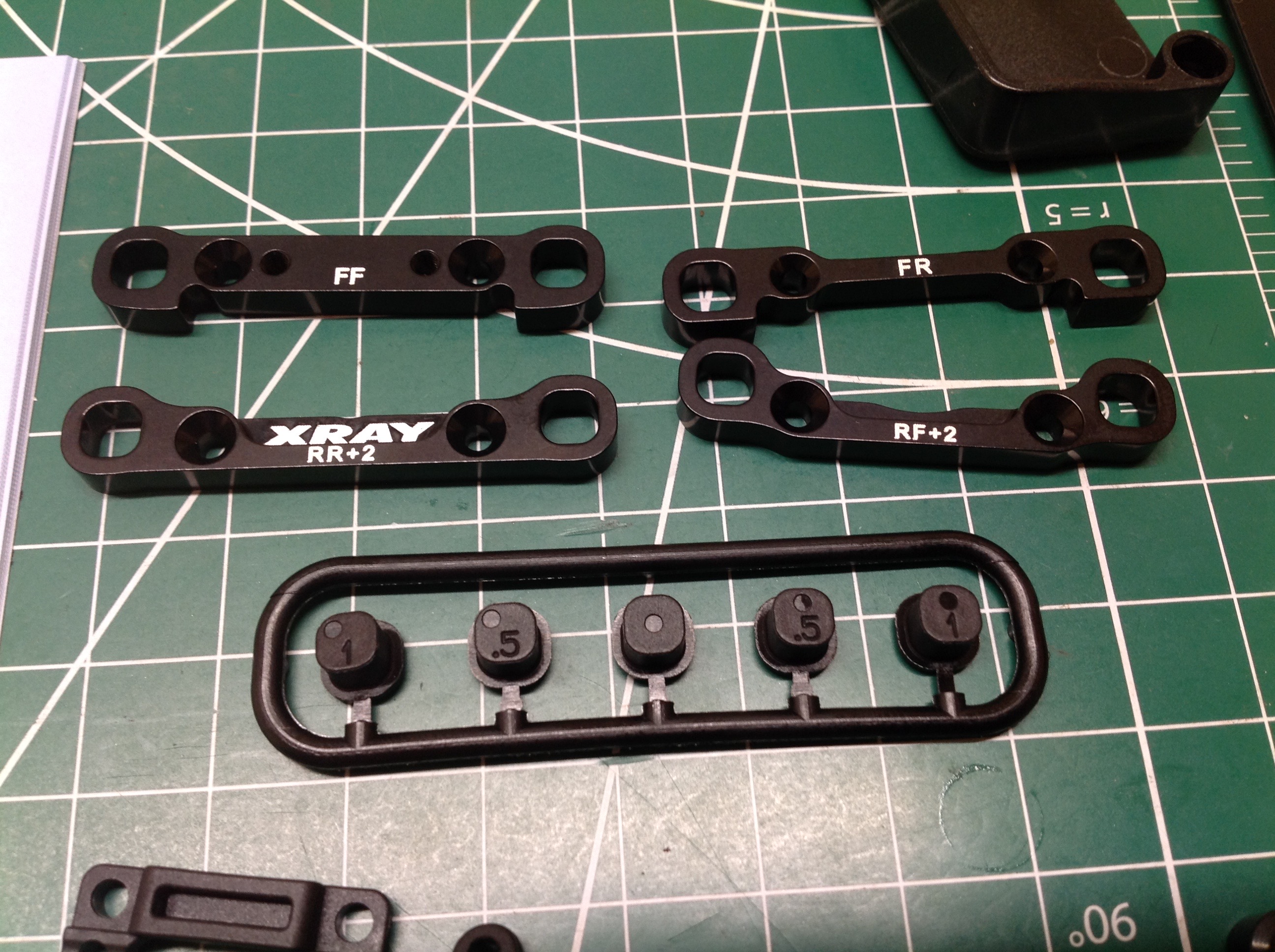
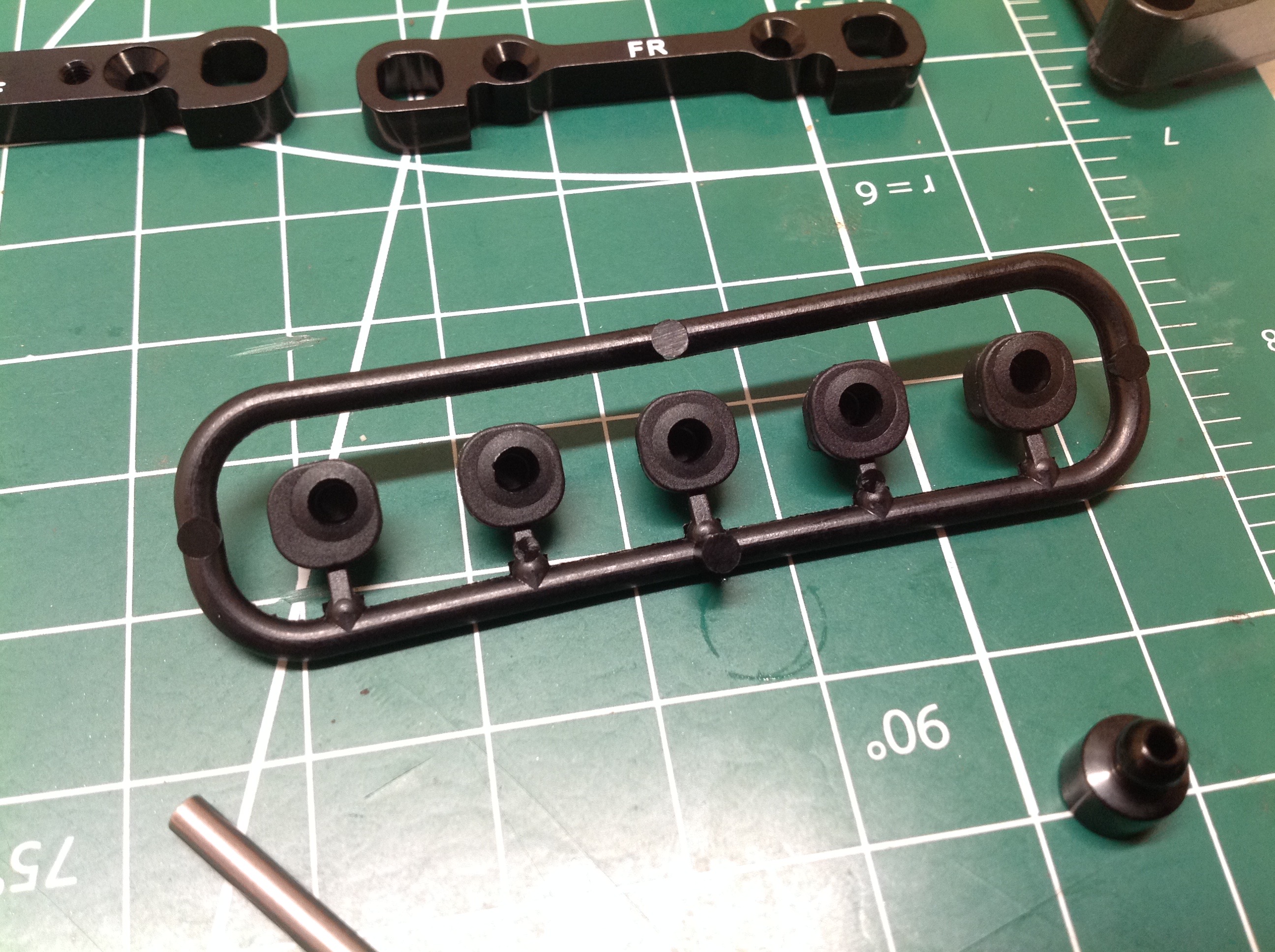
If there's one word that describes this model, it is "adjustable".
The suspension holders are thick aluminum and apply a built-in toe
angle in the lower suspension arms. By default this is 3º toe in
in the rear and zero in the front. Eccentric bushing inserts plug
into each end of the suspension pivot pin and allow even further
adjustment. The picture on the right shows the range of
inserts. The hole can be centered in both axes, and also offset
either 0.375mm or 0.75mm toward the edge or toward the corner.
Since every insert can also be rotated, this makes for a total of 17
possible positions at each end of each pin. That's a lot of
options. By default, all of the inserts are installed using the
center position.
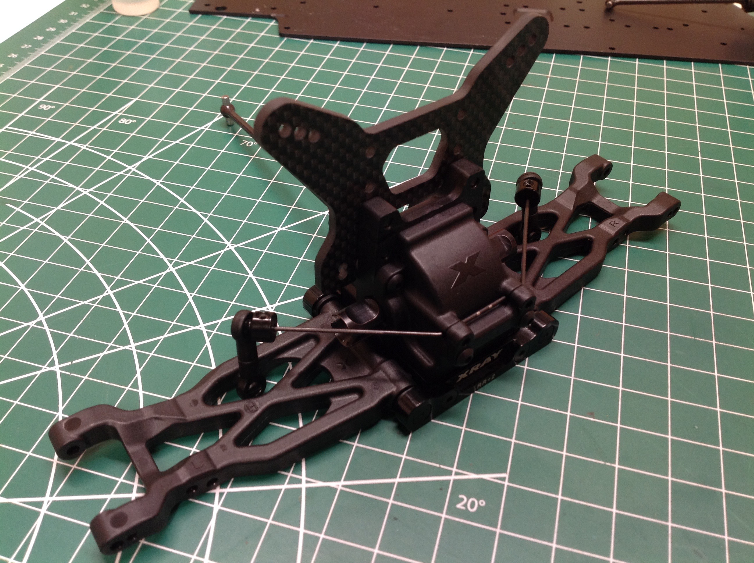
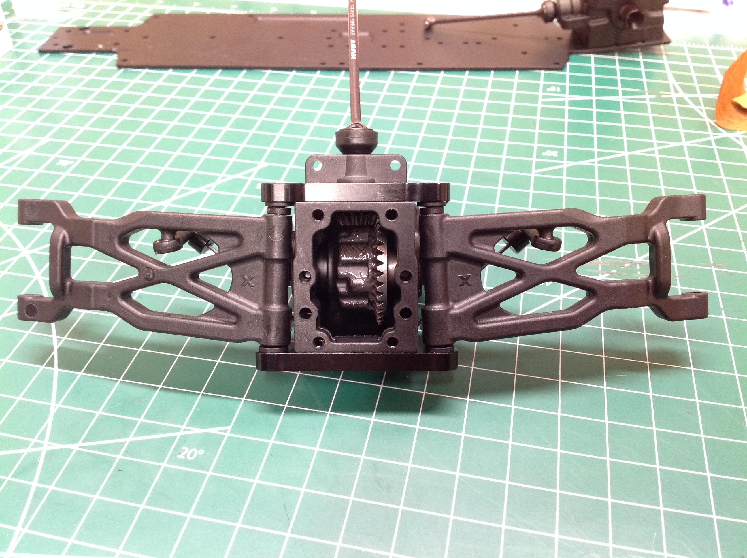
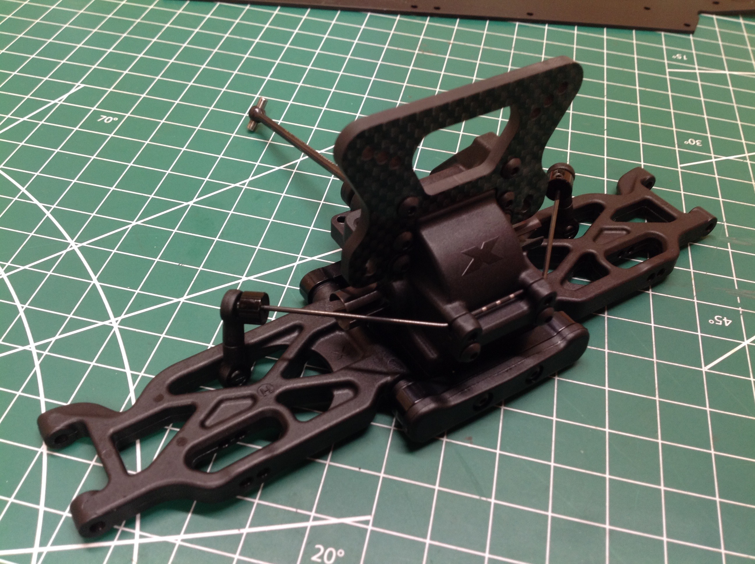
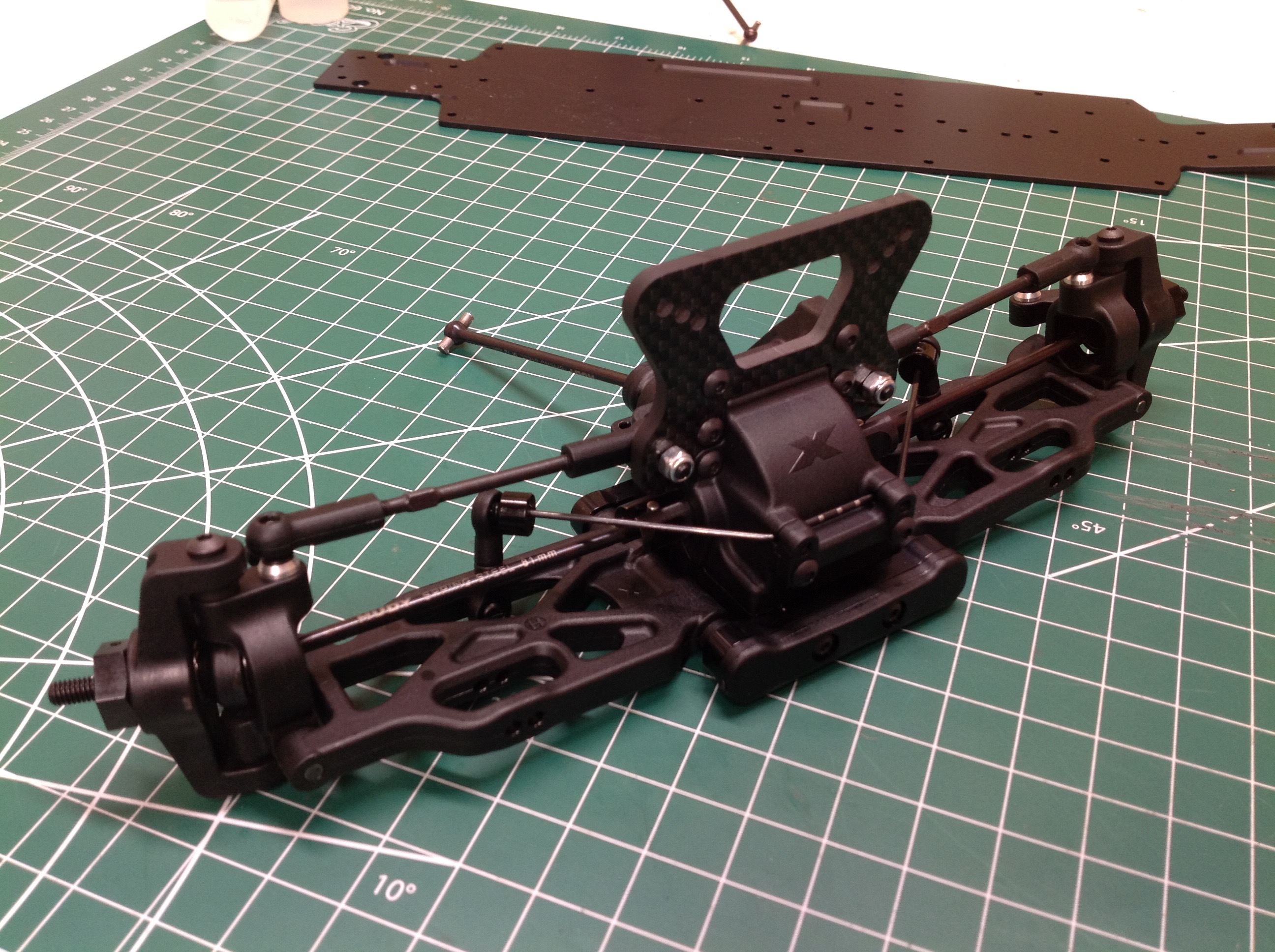
Here is the rear suspension assembly including the lower arms and
bulkhead. From below, you can see the differential ring gear and
the 3º toe angle is visibly evident. This toe angle can be
adjusted anywhere from 1º to 5º (3º ± 2º). A different insert on
the front and back of the arm offset laterally will adjust the toe angle
while similar inserts will change the track width. A different
insert on the front and back of the arm offset vertically will adjust
the anti squat angle while similar inserts will change the roll
center. The anti squat angle can be adjusted anywhere from 0º to
4º (2º ± 2º). There is also a 2mm shim in front of the lower
arm. Changing or moving the shim configuration adjusts the
wheelbase. The kit comes with a 1.2mm diameter rear sway bar, but
optional bars from 1.0mm to 2.0mm are available.
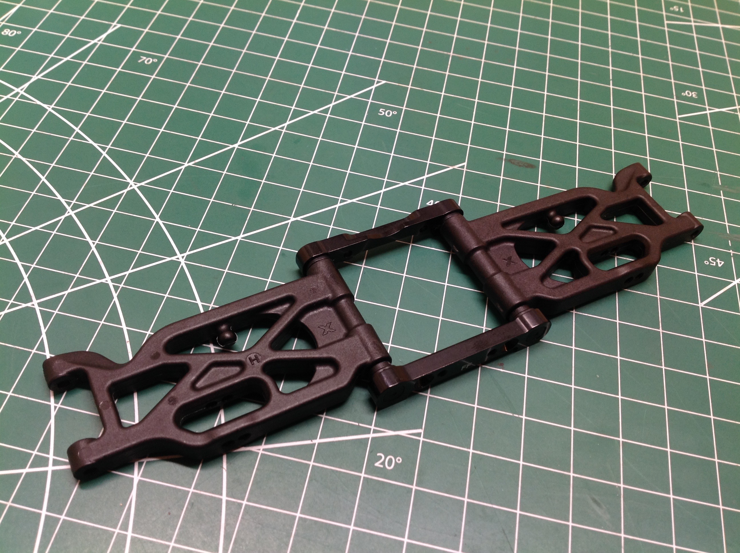
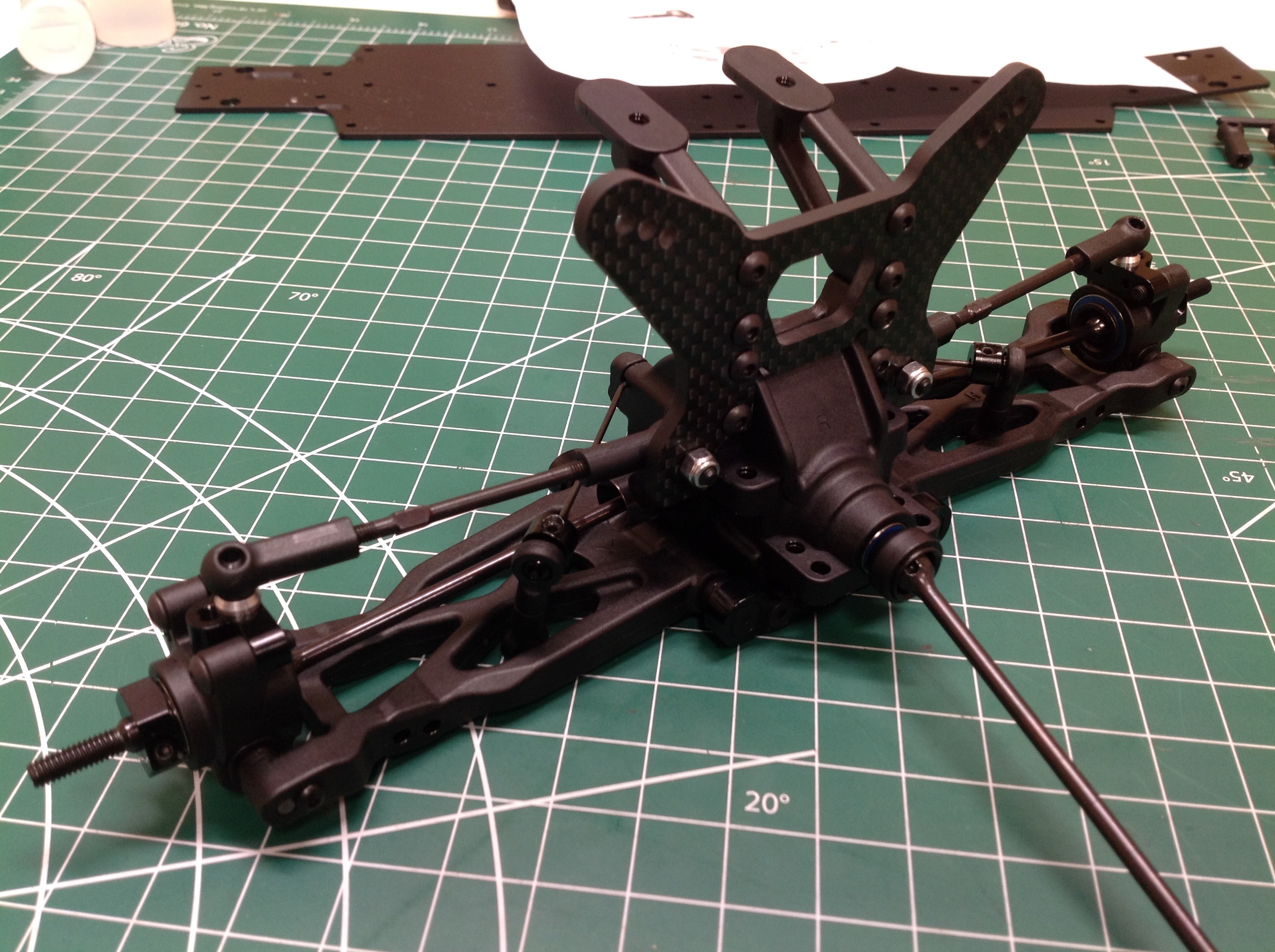
The front suspension is similar but there is no toe angle built into the
suspension holders. Toe is adjusted by altering the
steering rod lengths instead. A similar insert on the front
and back of the arm offset laterally will
adjust the track width.
A different insert on the front and back of the arm offset vertically
will adjust the kick up angle while similar inserts will change the
roll center. The kick up angle can be adjusted anywhere from 7º to
11º (9º ± 2º) using the inserts, but the total caster angle is the sum
of the kick up angle built into the chassis and the caster angle built
into the C-hub. There is also a 2mm shim in front of the lower
arm.
Changing or moving the shim configuration adjusts the wheelbase.
The
kit comes with a 1.3mm diameter front sway bar, but optional bars from
1.0mm
to 2.0mm are available.
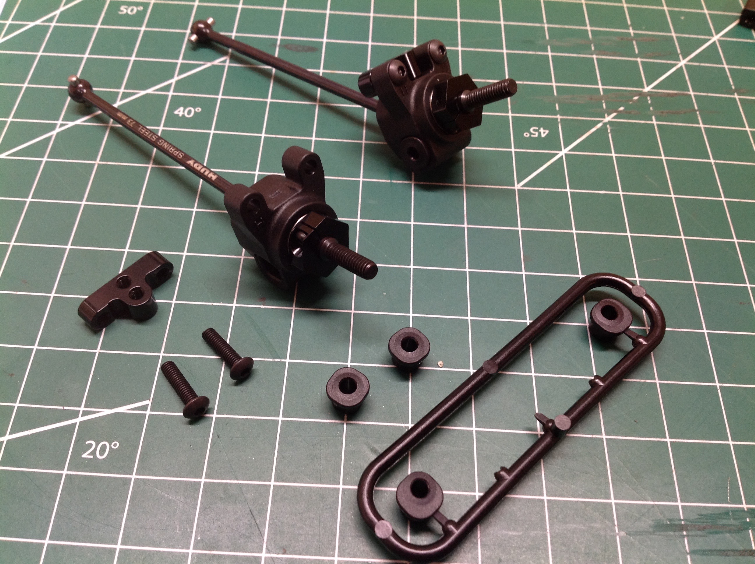
If you thought that was the end of the adjustability, you weren't even
close. Another set of eccentric bushings and spacers are used to
attach the rear upright. The spacers can be used to adjust the
wheelbase while the inserts impact track width and probably other things
I don't understand. The length of the upper arm, adjustable with a
turnbuckle, controls camber while the choice of attachment holes at
both the inboard and outboard ends impacts roll center. There are 3
potential attachment points at the hub and 2 at the shock tower.
Even the length of the drive axle is adjustable by altering which pin
hole is used inside the CVD joint.
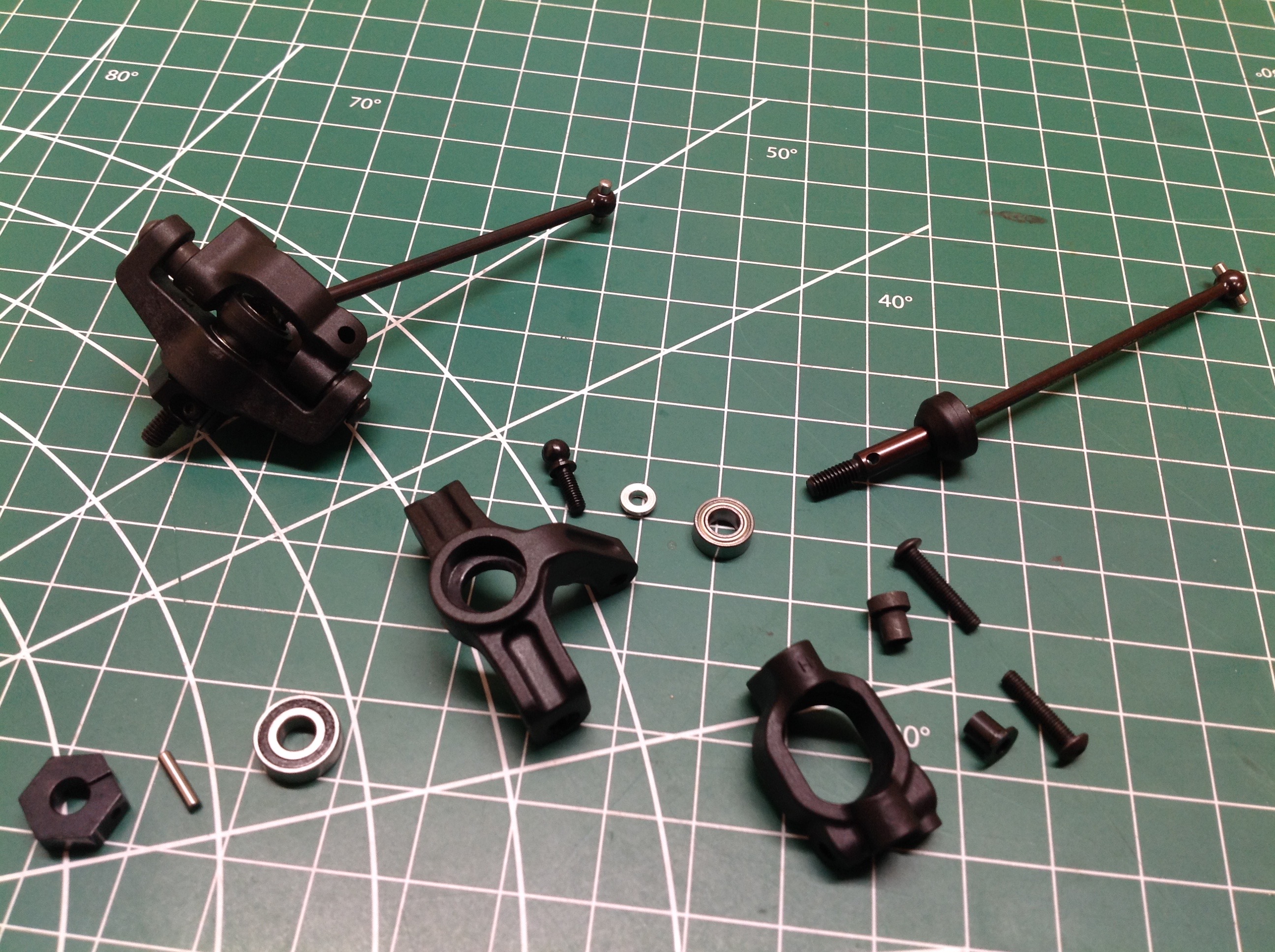
You'd think things would get even more complicated up front because the
wheels steer, but the longitudinal position of the C-hub is actually not
adjustable nor is the length of the drive axle. The height of the
C-hub is adjustable with variable thickness bushings which changes the
roll center. The C-hub in the kit has a caster angle of 6º, but an optional 9º hub
is available. This means the total range of caster angle
adjustment is from 13º to 20º. If you buy an aluminum hub you can
go 3º further. The length of the upper arm, adjustable with a
turnbuckle, controls
camber while the choice of attachment holes at the inboard end impacts
roll center. There are 2 potential attachment
points at the the shock tower.
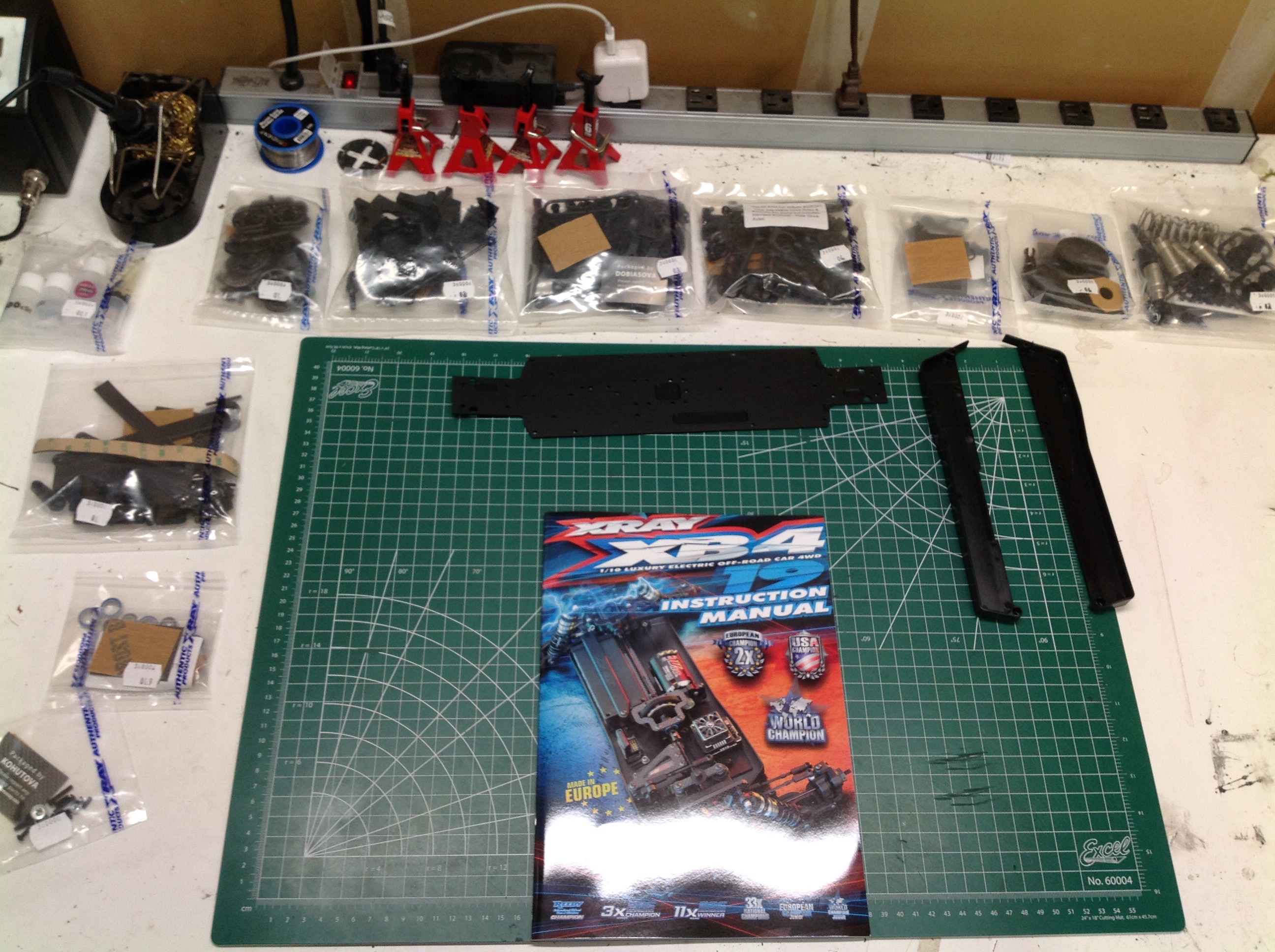
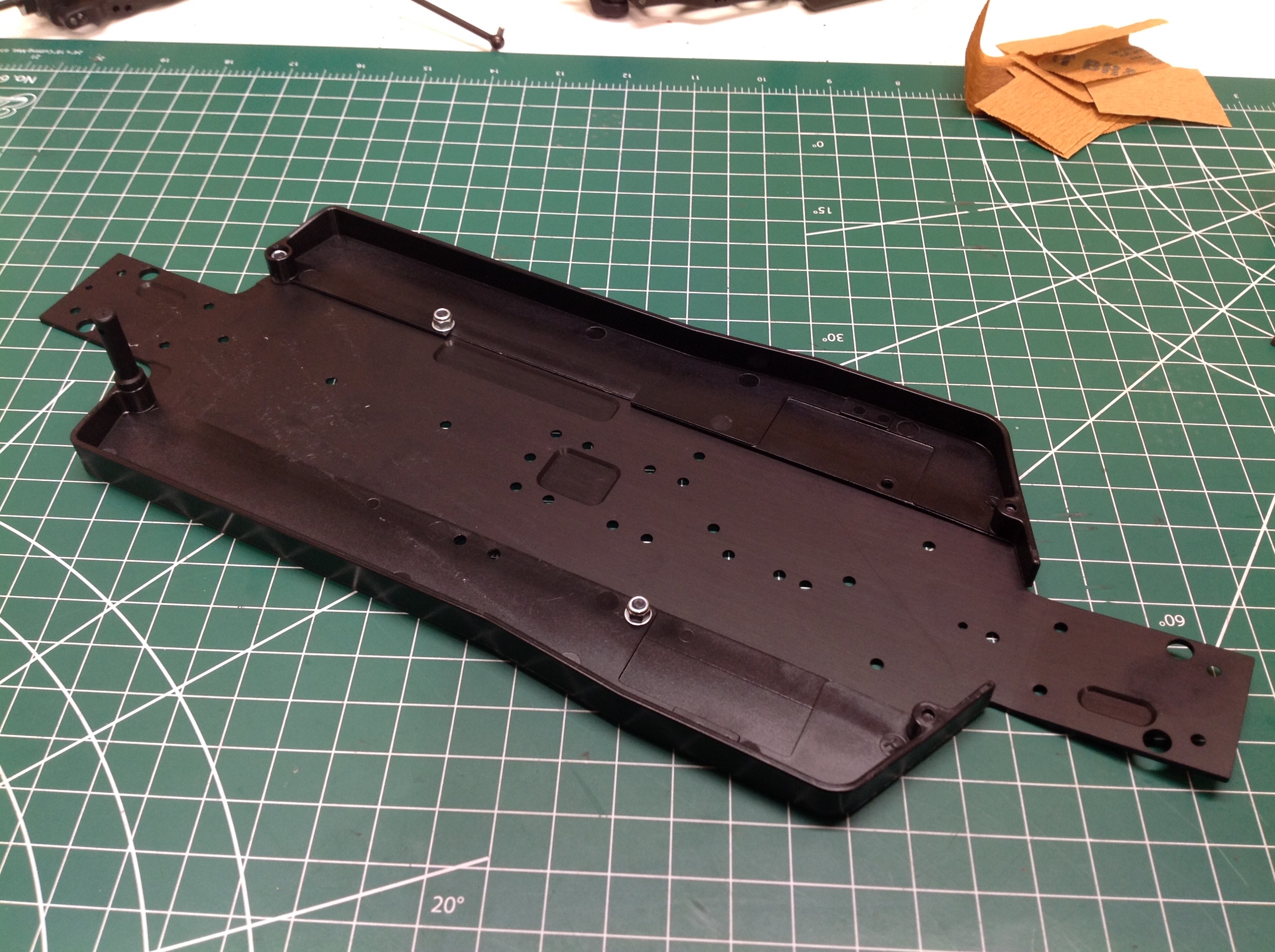
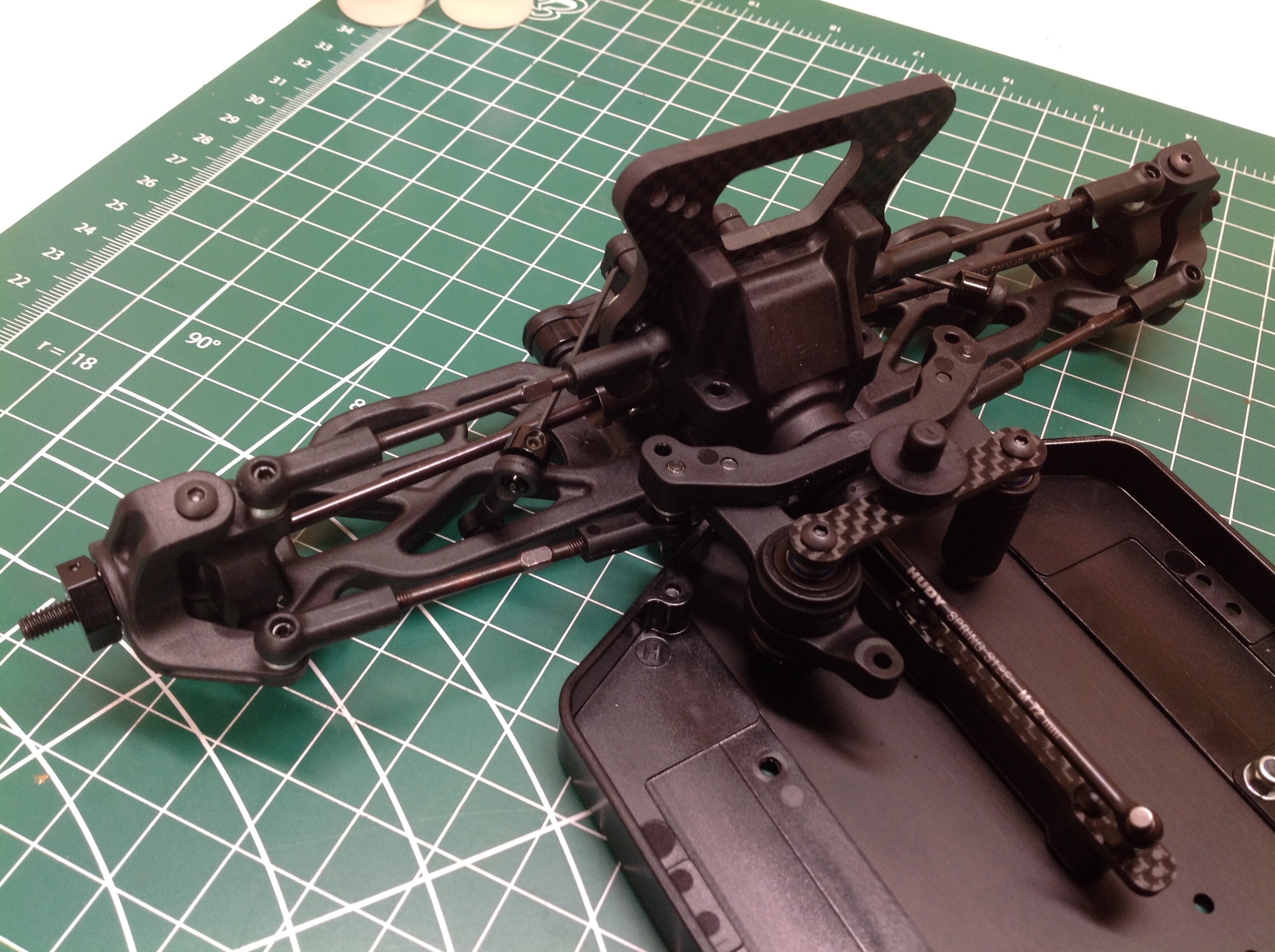
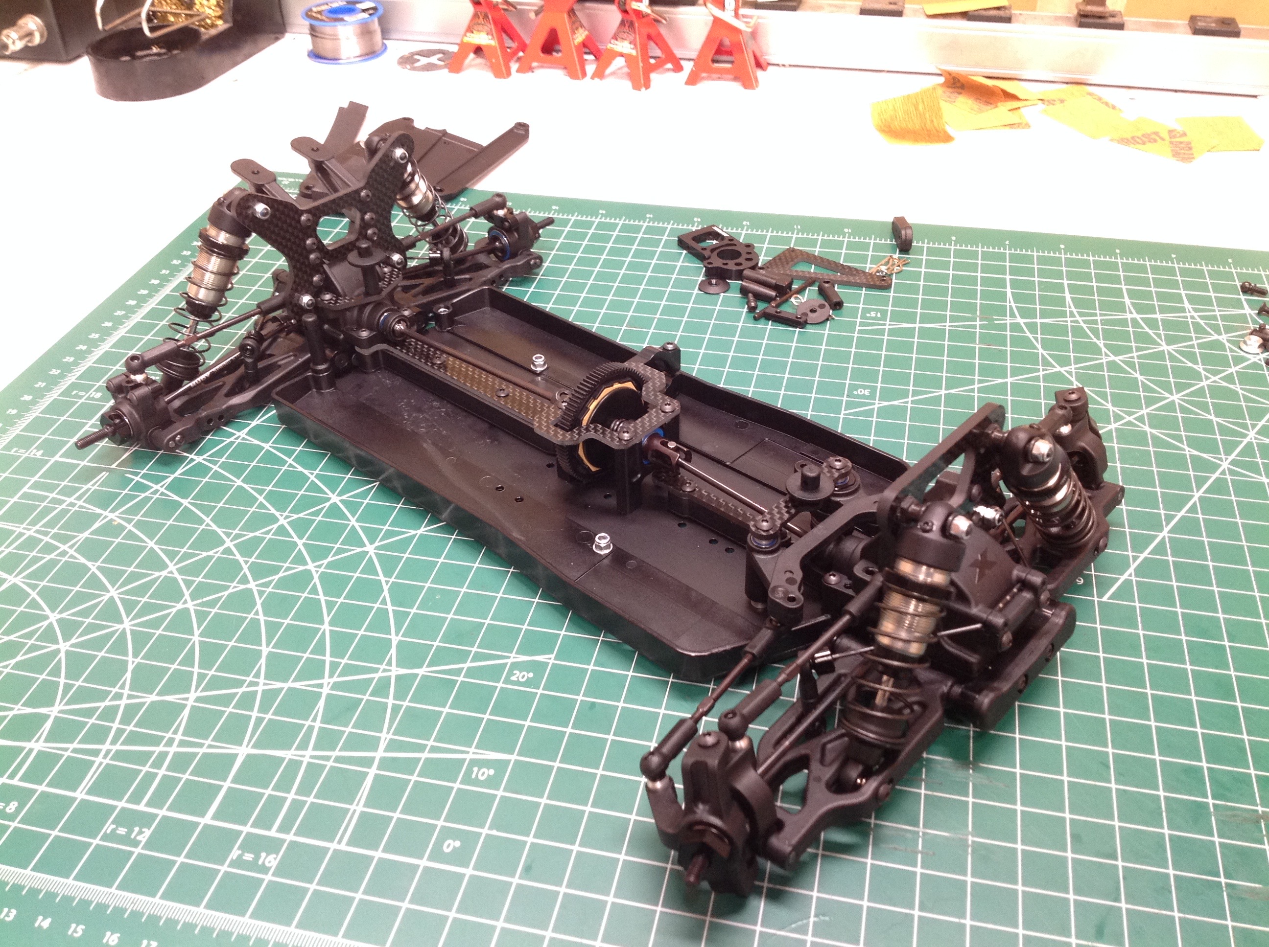
The suspension modules are finally done so that means we can start work
on the chassis. The chassis plate is 2mm and made from 7075-T6
aluminum alloy. If you know anything about aluminum, you'll be
aware that this is one of the strongest aluminum alloys available,
stronger than mild steel but 3x less dense. That wasn't good
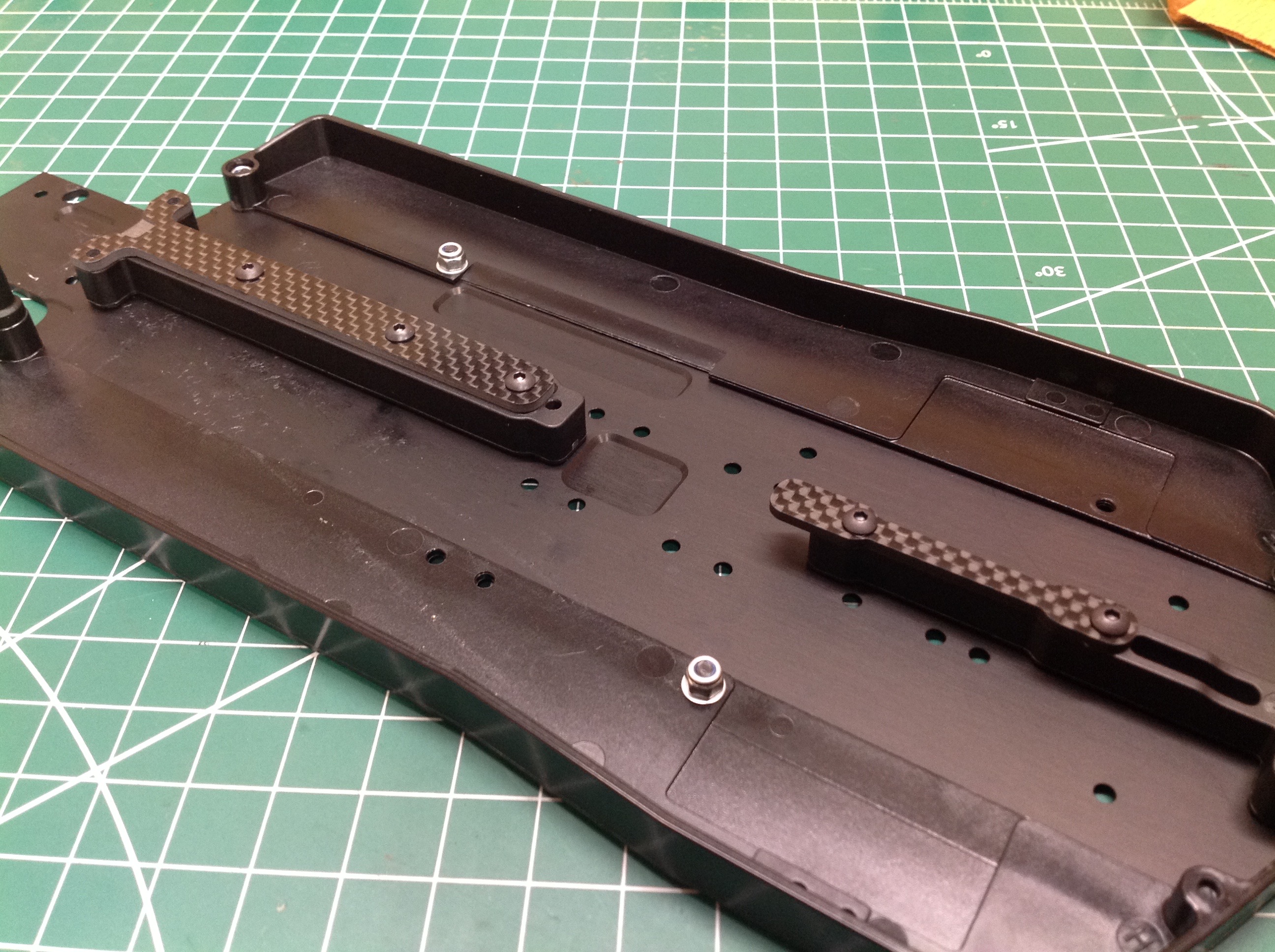
enough for XRay though. The composite side guards further increase
the stiffness by increasing the moment of inertia, as do the center
braces. In the kit are front and rear composite center braces and
then graphite plates on top of them. Optional softer center braces
are available to adjust chassis flexibility as are brass plates to
adjust the weight and balance.
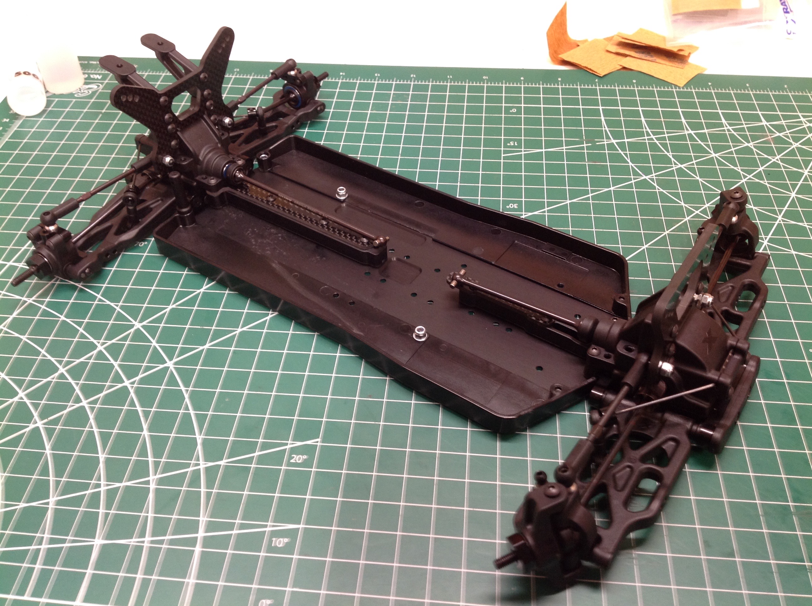
Now the suspension assemblies can be attached to the chassis. An
optional spacer can bu put in the rear to lift the entire rear
suspension and make the drive shaft angle more level for some reason.
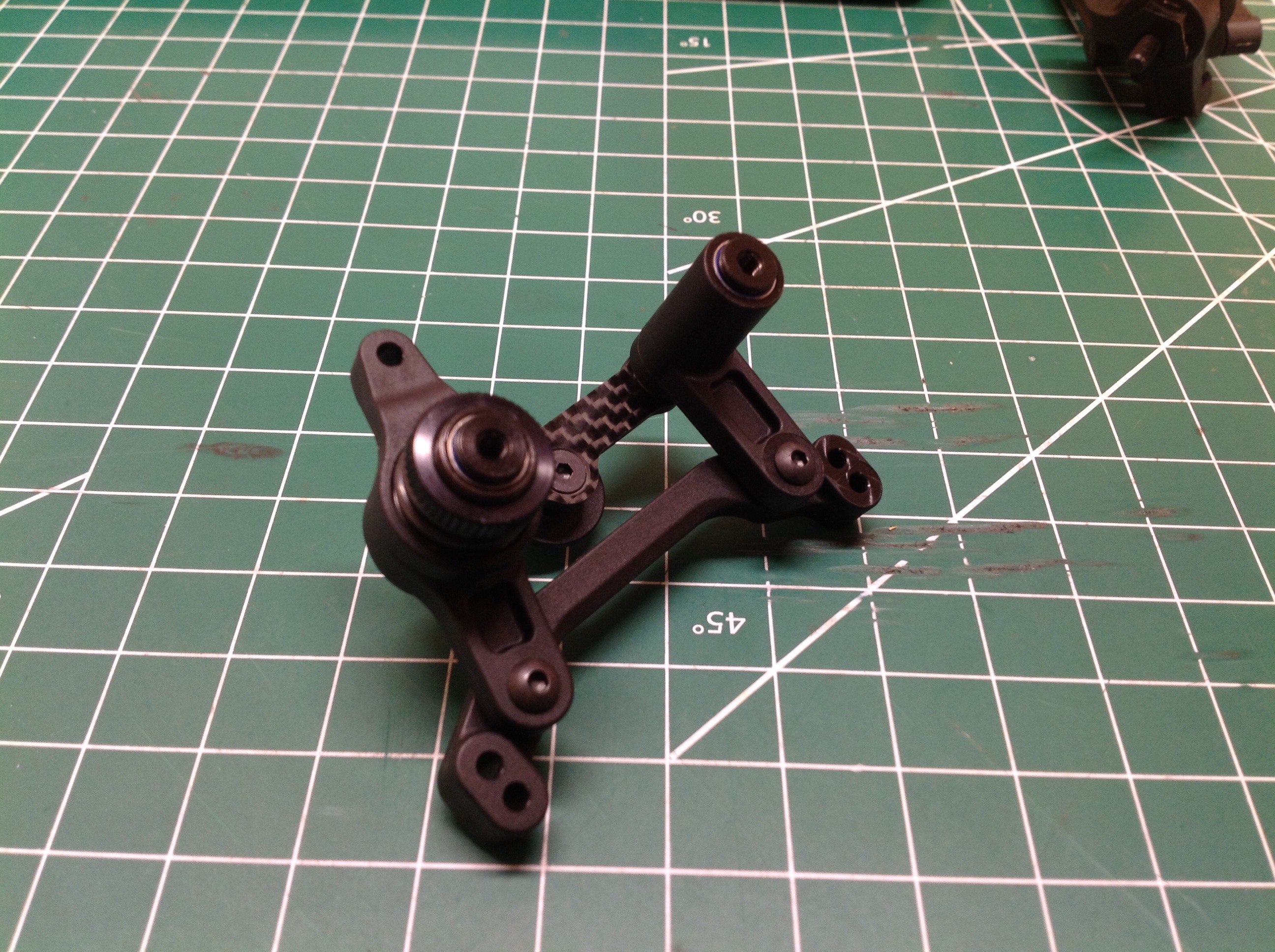
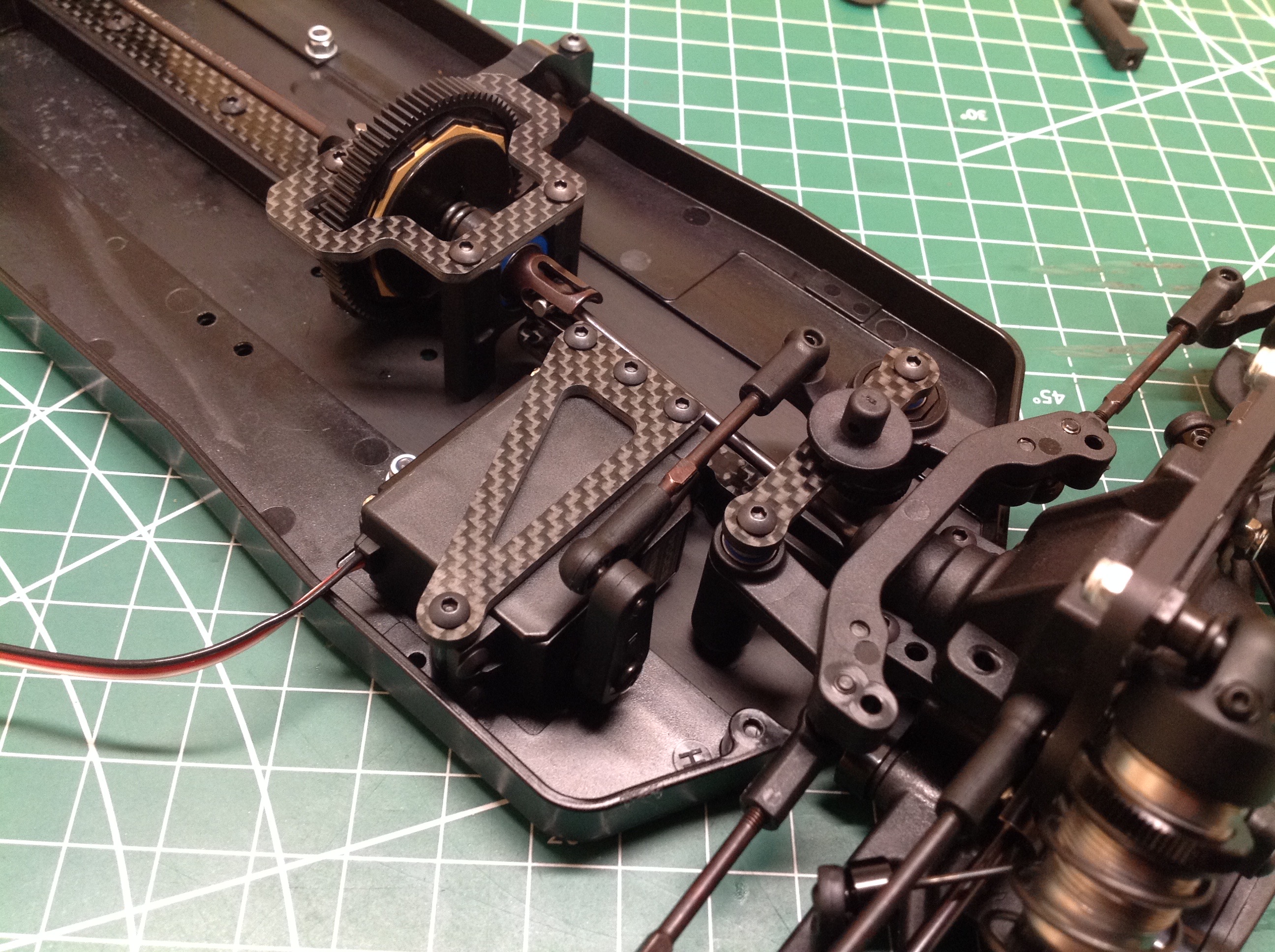
The steering uses a dual bellcrank system with ball bearings. The
tightness of the servo saver is adjustable by using the large nut on top
to compress the spring. There are multiple holes on the steering
plate allowing adjustment of the Ackerman angle. Bump steer can be
adjusted by adding or subtracting shims to the ball joint which
attaches the steering link to the steering plate, effectively moving the
inboard end of the link up and down.
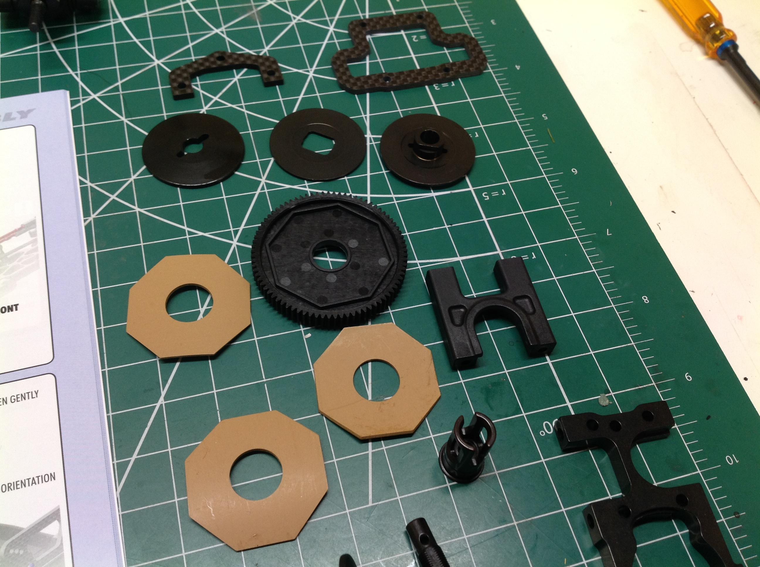
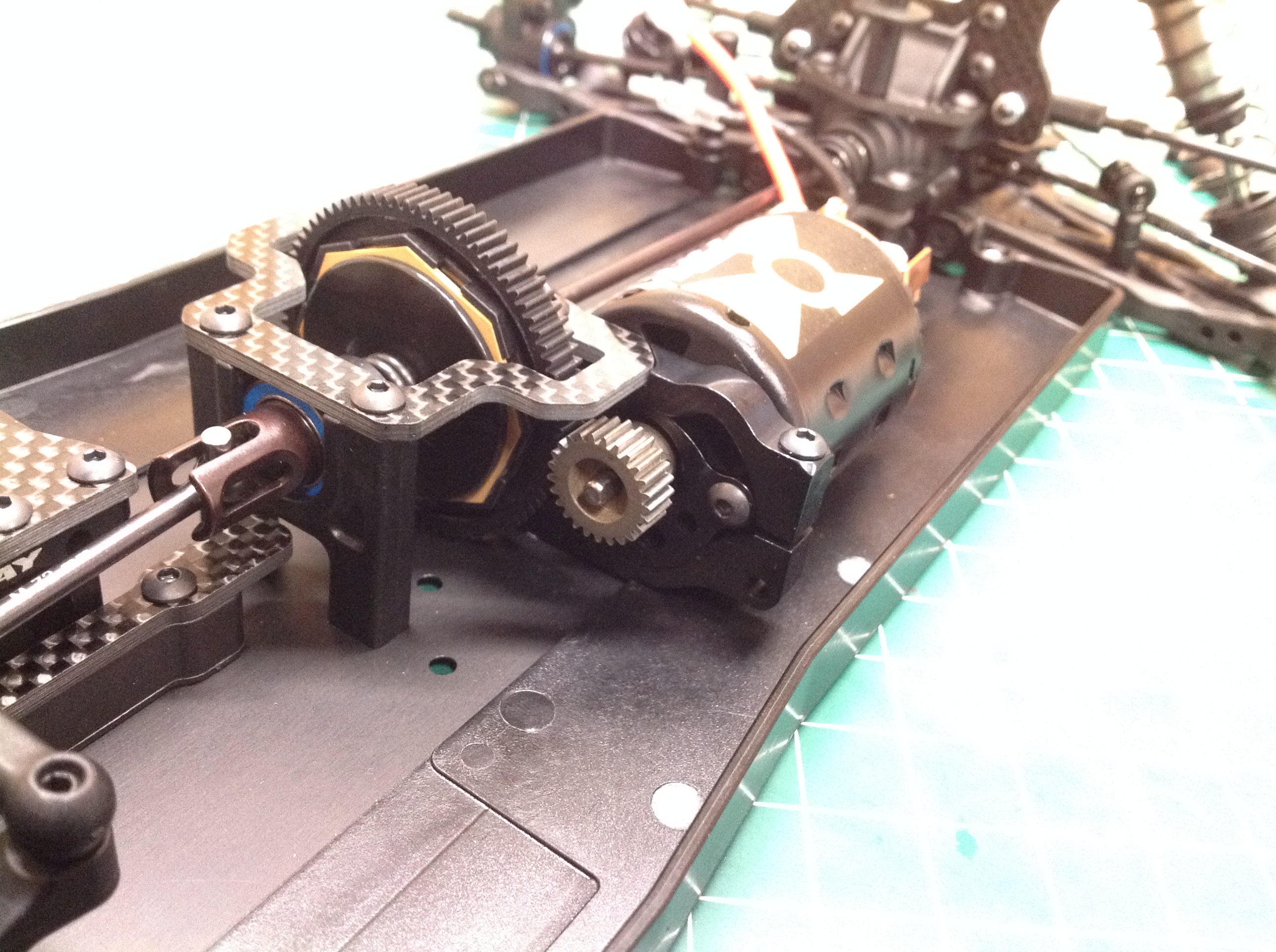
The slipper clutch assembly is integrated into the 81 tooth, 48 pitch
spur gear. The slipper uses 3 friction pads and has adjustable
slip. The default setting is very tight. Optional spur gears
from 75T to 87T are available. The entire slipper can also be
replaced with a center ball differential.
The slipper assembly installs in the center of chassis, slightly closer
to the front. One of the aluminum bearing supports doubles as the
motor mount. A carbon plate spans the bearing supports and
surrounds the top of the spur gear. The entire motor assembly can
be installed in multiple positions. The default position is
forward, but the whole thing can be moved 10mm back which requires
changing to different length drive shafts.
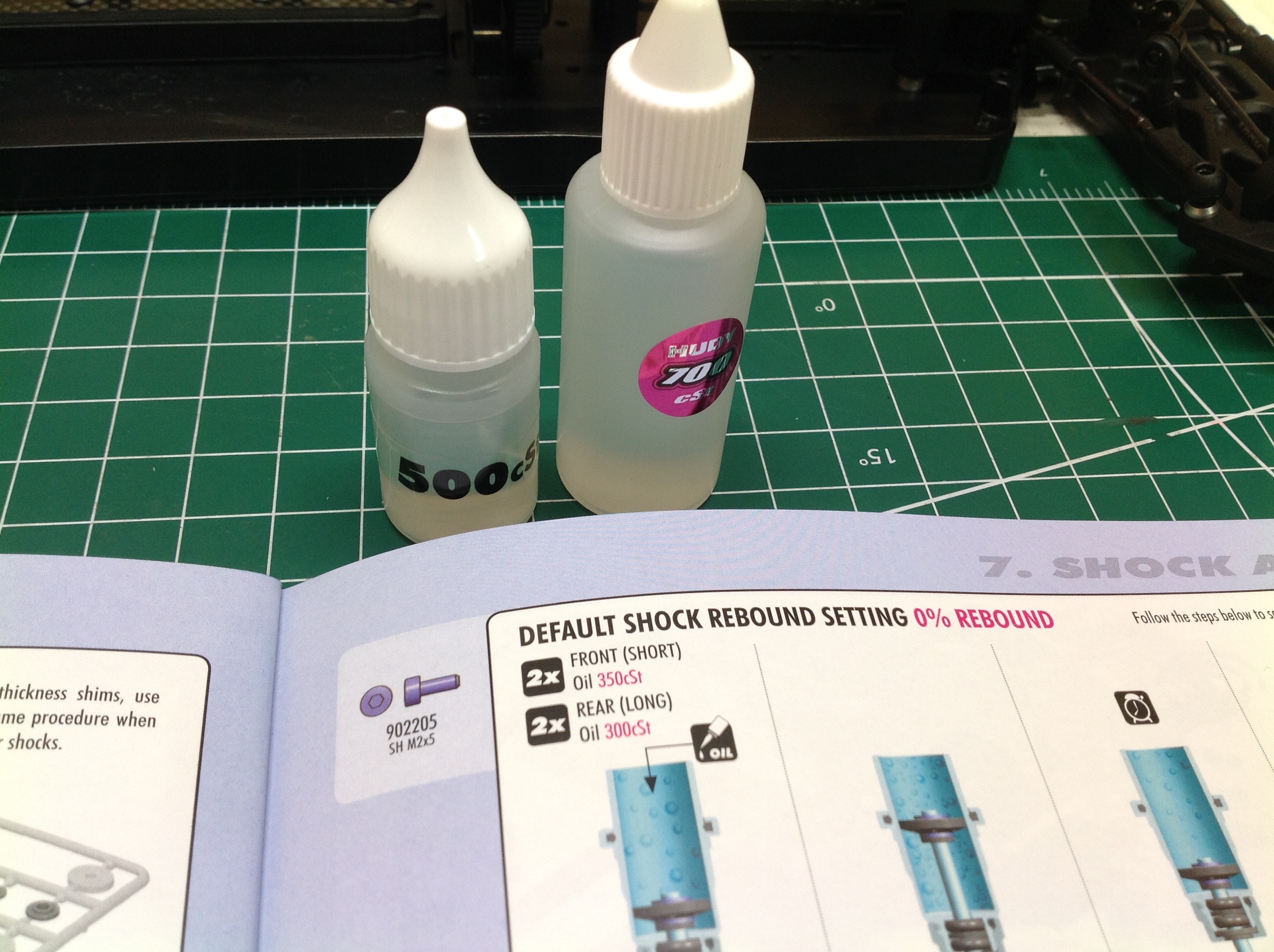
The aluminum big bore shocks have plastic caps and spring perches, but
these can be upgraded to aluminum. The picture on the right shows
an oddity of the kit. The manual recommends shock oil with a
weight of 350cSt in front and 300cSt in the rear, yet the oil that comes
in the box is 700cSt and 500cSt. I think this was an error in the
manual, because the PDF version of the manual I downloaded shows 500
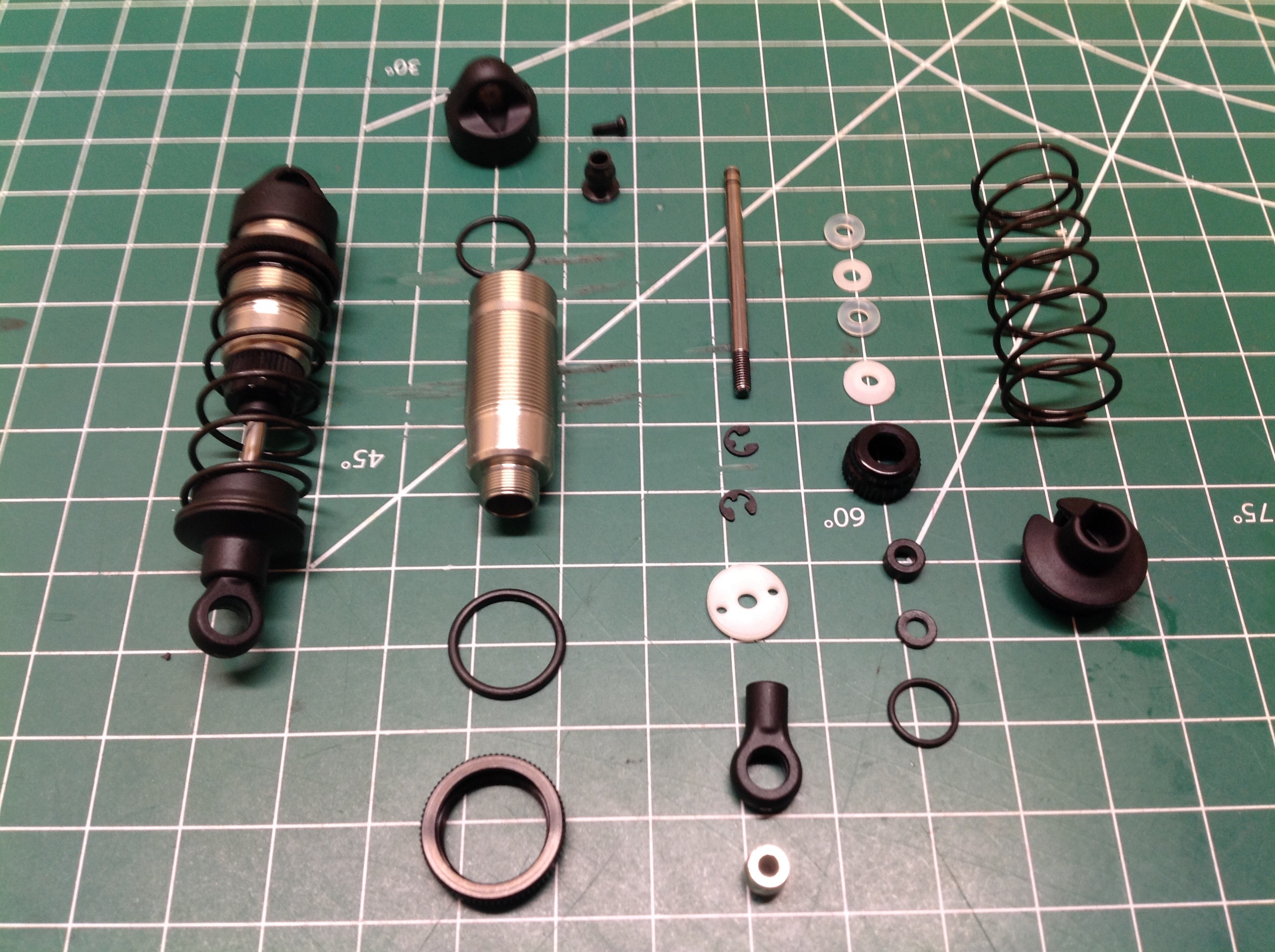
and 700. The buildup of the shocks is similar to that in other
kits except with more adjustability. The pistons that come in the
kit have 2 holes of either 1.6mm or 1.7mm diameter. An undrilled
piston is also included to allow full customization. There is no
volume compensation bladder, instead the fluid volume is adjusted using a
bleed screw in the cap. The springs that come in the kit have a
linear spring rate. Three other optional linear rates are
available as well as two progressive rates. The spring preload can
be adjusted with the nut on the threaded shock body to change ride
height.
There are multiple shock attachment points on the body. The rod
end of the shocks attach to the lower suspension arms at one of two
positions. The outer hole is used by default. The head end
of the shocks attach to the shock tower at one of three positions.
The center hole is used by default. The rear shocks can be installed either ahead of or behind the shock tower.
The servo mounts in an unusual way. Although there are brackets on
both sides of the servo, only the inboard bracket actually attaches to
the chassis. The outer end is just hanging in space, cantilevered
from the inner end and stiffened by a carbon plate. This is
presumably to decouple the steering forces from any flex in the
chassis. The aluminum motor mount uses an eccentric cam to adjust
pinion mesh. While the manual says you can use pinions anywhere
from 18 teeth to 38 teeth, that range is not possible with the stock
spur. Larger pinions require a smaller spur and vise versa.
Running the numbers, it looks like overall final drive ratio can be
modified from 4.93:1 to 12.08:1, a huge variation in speed and
torque. No pinion is included in the kit so I used a 25 tooth to
start along with a temporary brushed motor while I saved up for a better
power system. The plastic servo shown is also temporary.
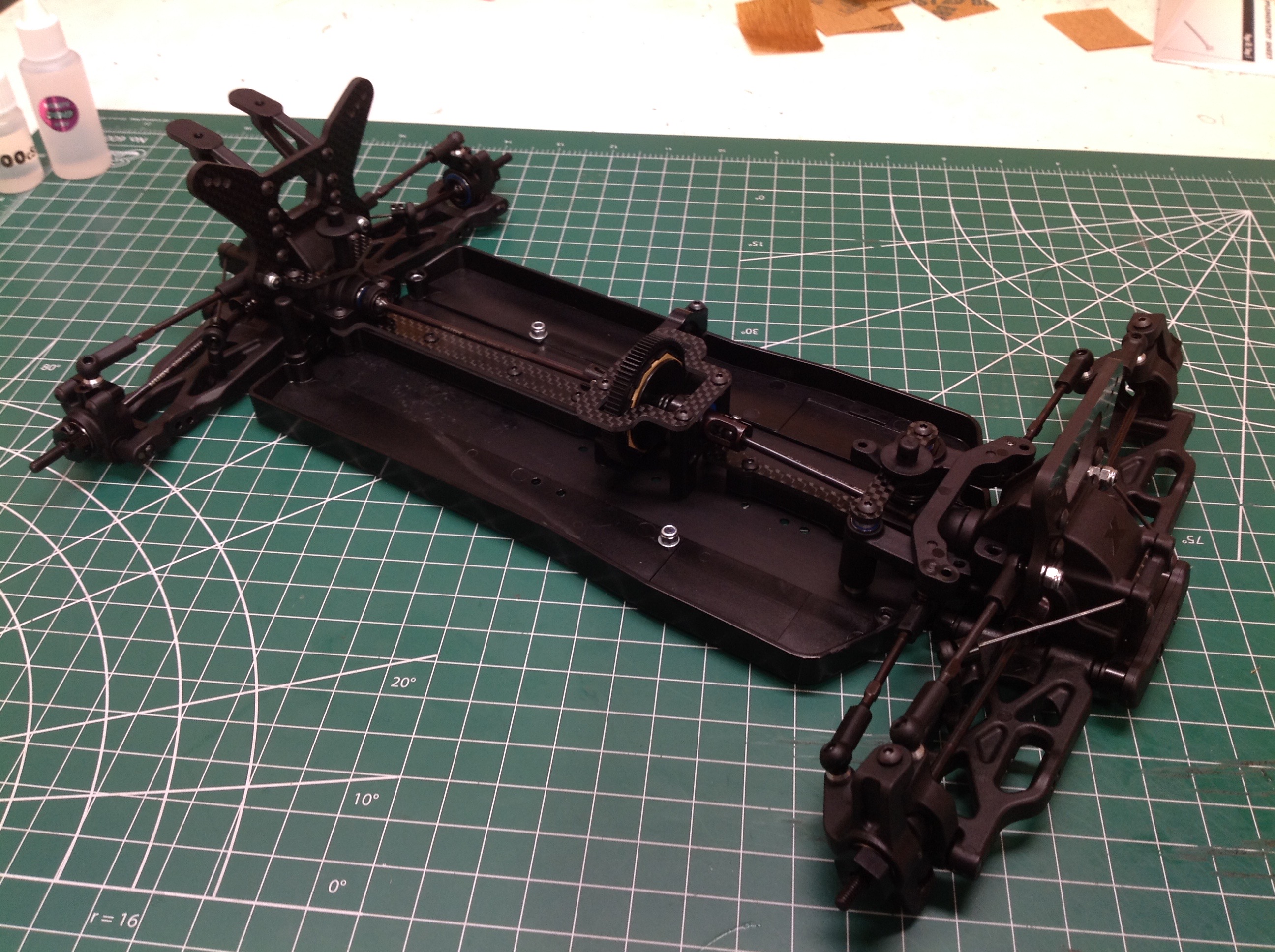
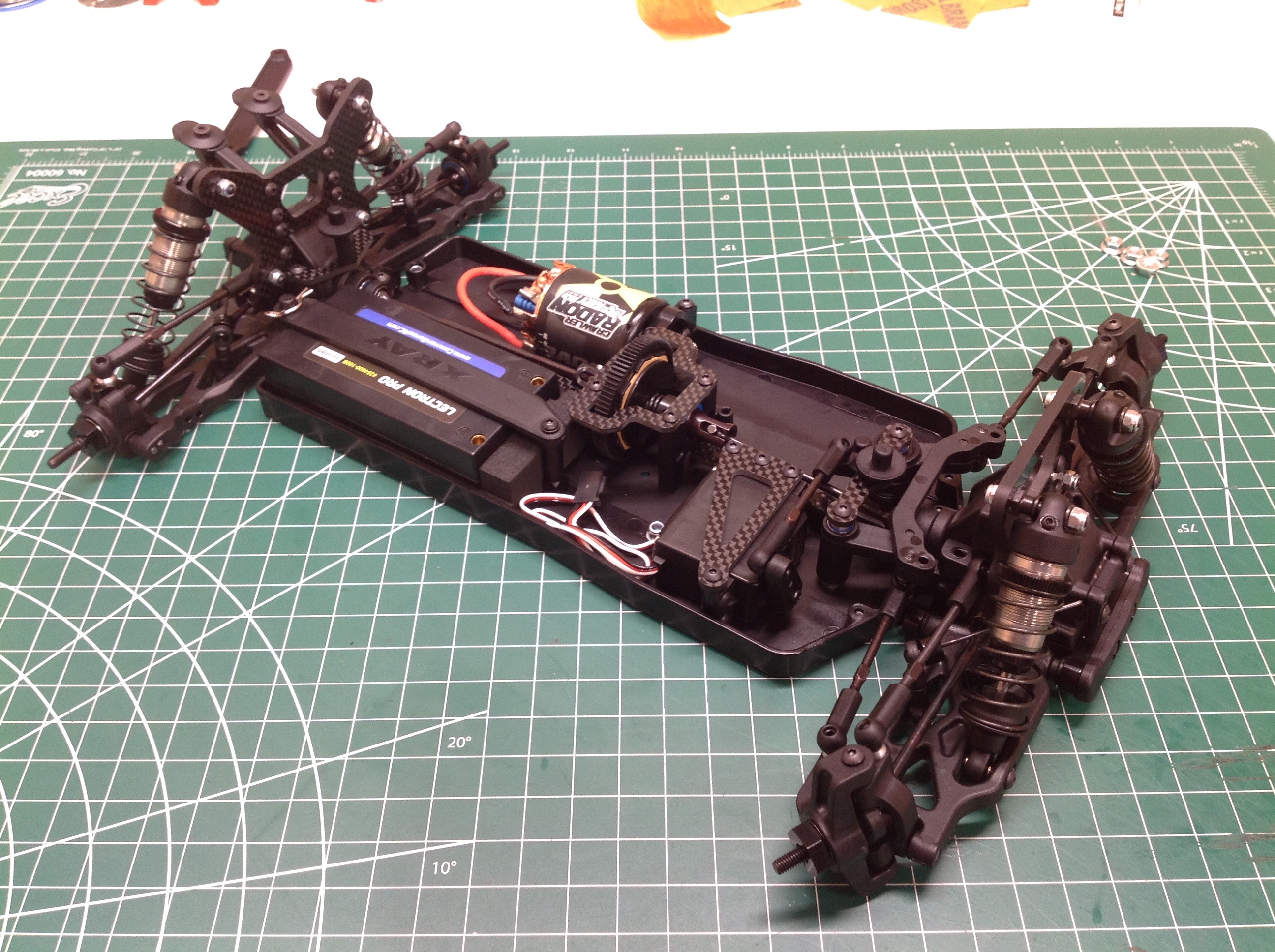
The electronics install on a floating tray in the left front corner for
easy removal. A shortly Li-Po battery pack installs in the right
rear corner. There was an obvious effort made to balance the items
of mass in this chassis. The battery can be moved about 5mm front
or back using a foam spacer block to control balance.
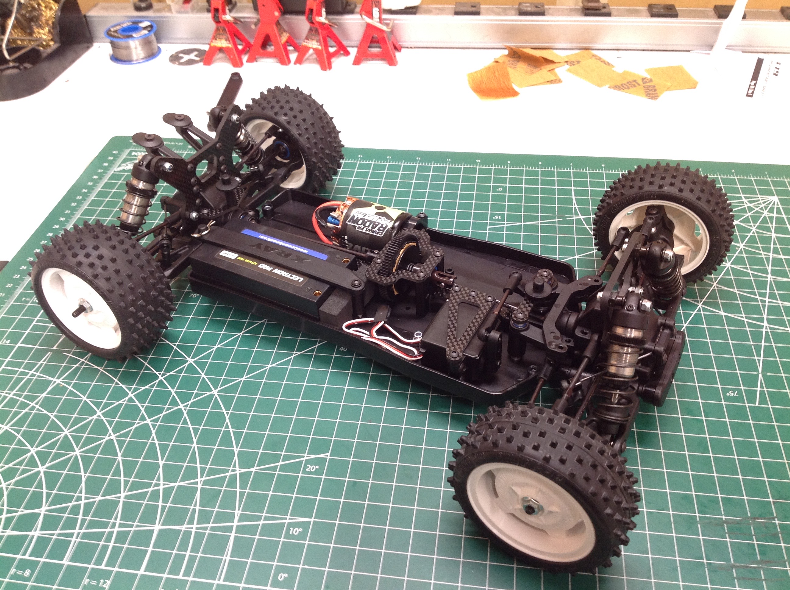
The tires you see here are some cheap extra Tamiya tires I had sitting
around which I used while deciding what to use on a more permanent
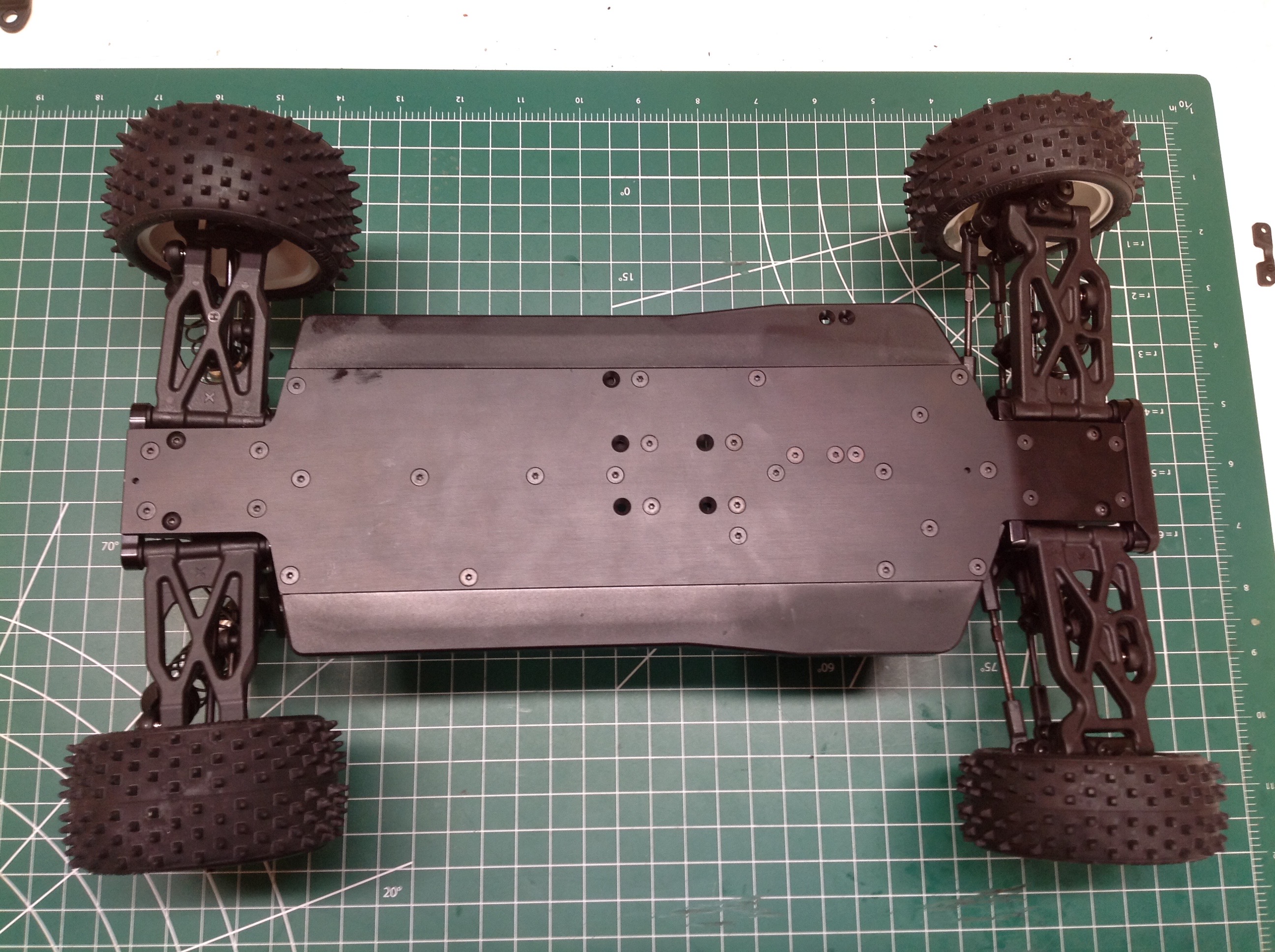
basis. From the bottom you can see the open holes for the
alternate motor position. All screws are countersunk and flush
with the bottom of the pan. Optional thickness wheel hubs can be used to alter the wheel offset.
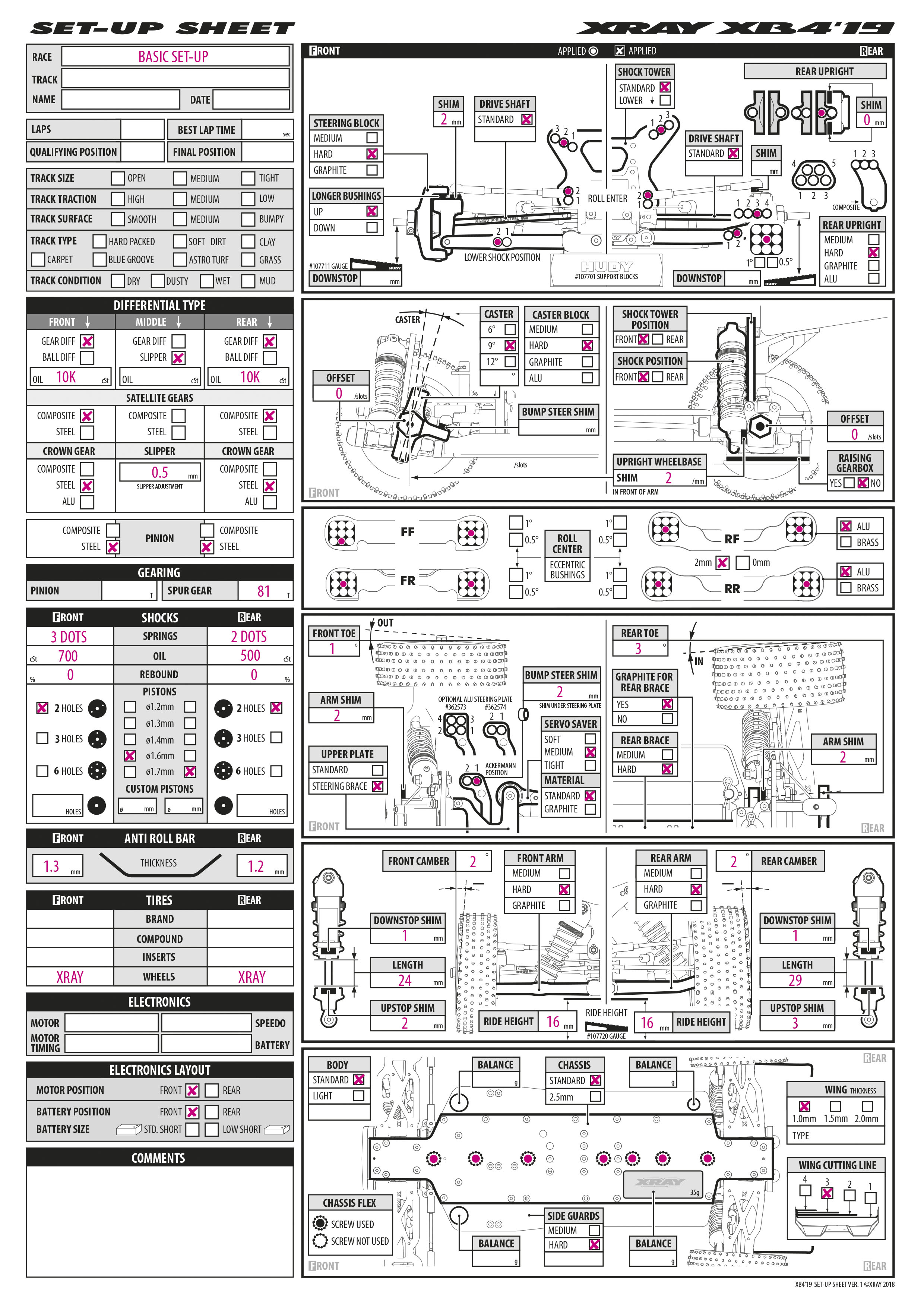
This sample setup sheet gives you an idea of just how must adjustability is available in this chassis.
©2019 Eric Albrecht