Tamiya XR311 Project
Page 1: Building the Chassis
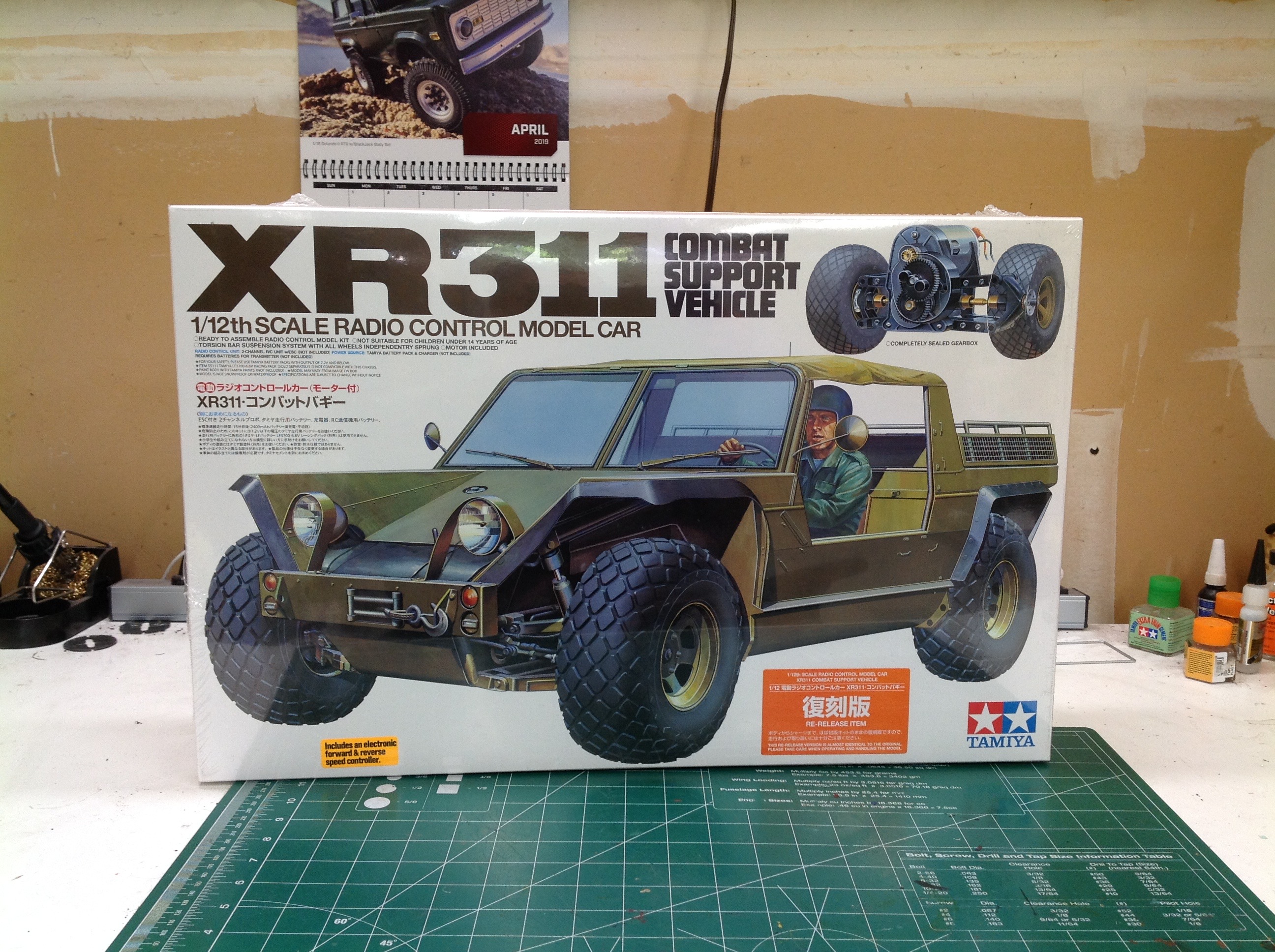
The XR311 comes in a large box with lovely artwork. Note that this
kit bears the same model number as the original so a special sticker
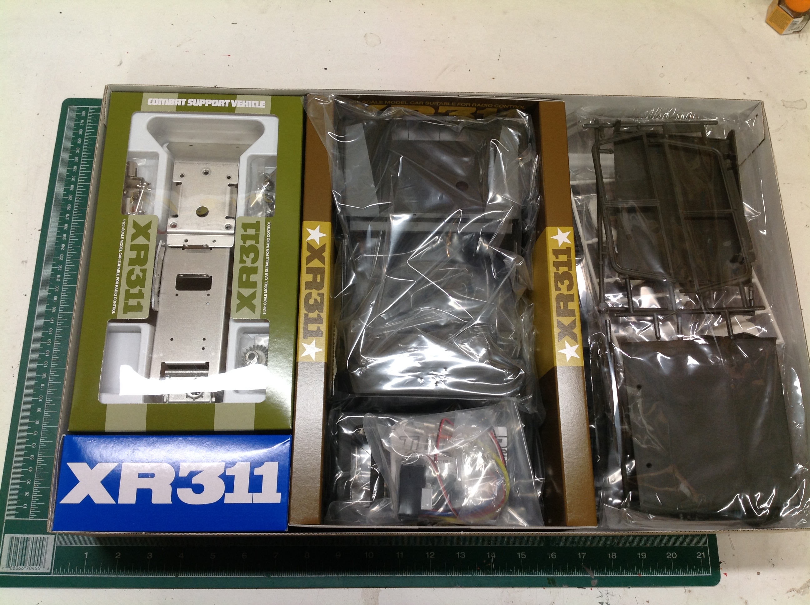
has been added to indicate that this is a re-release. Inside the
sections are nicely divided and the metal parts are segregated into a
smaller inner box with dividers to keep them safe.
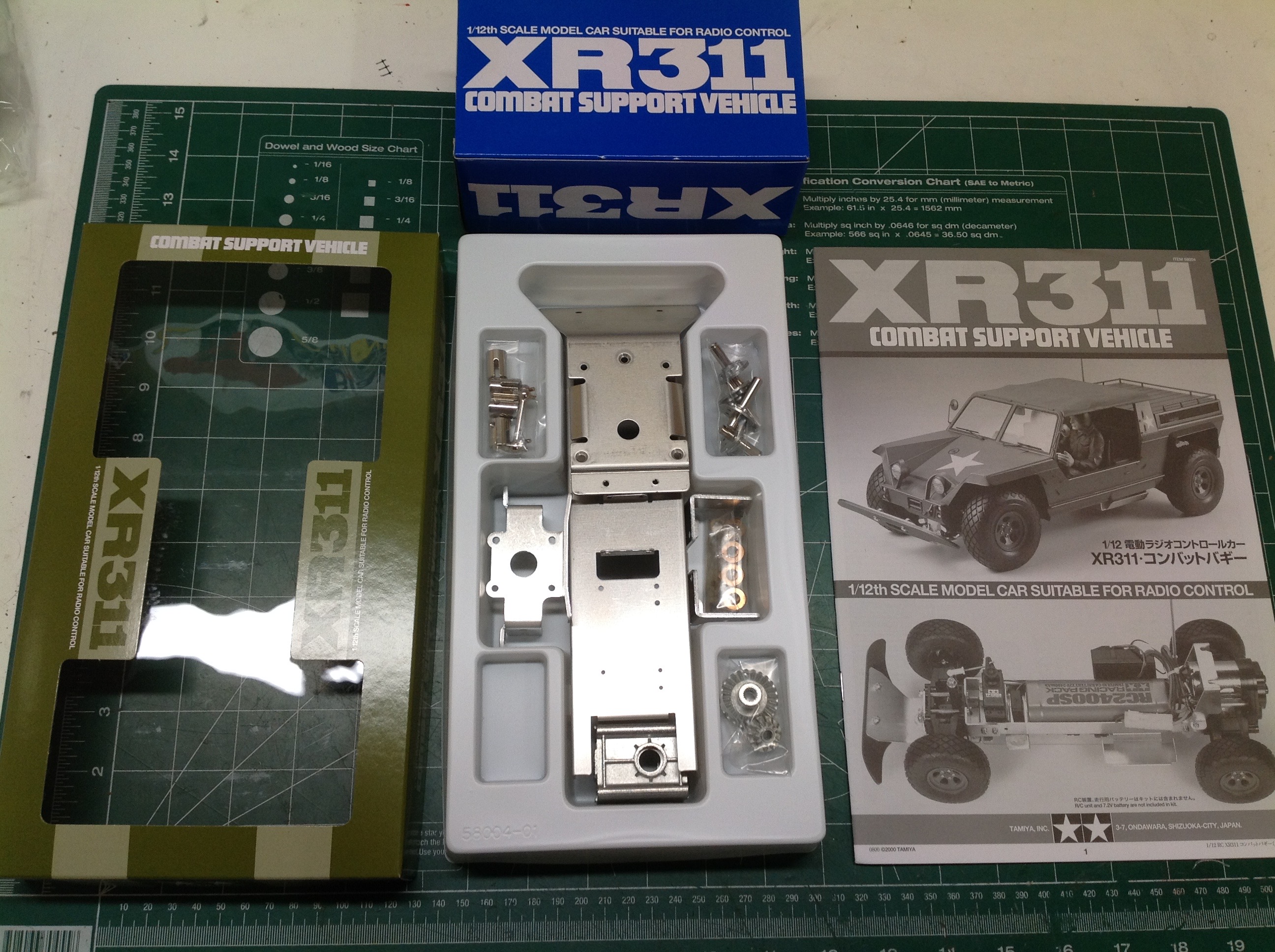
The left hand image shows the contents of the inner box for the metal
parts. This includes the chassis tray, the electronics sponsons
and the gearbox housing. The right hand image shows the fairly
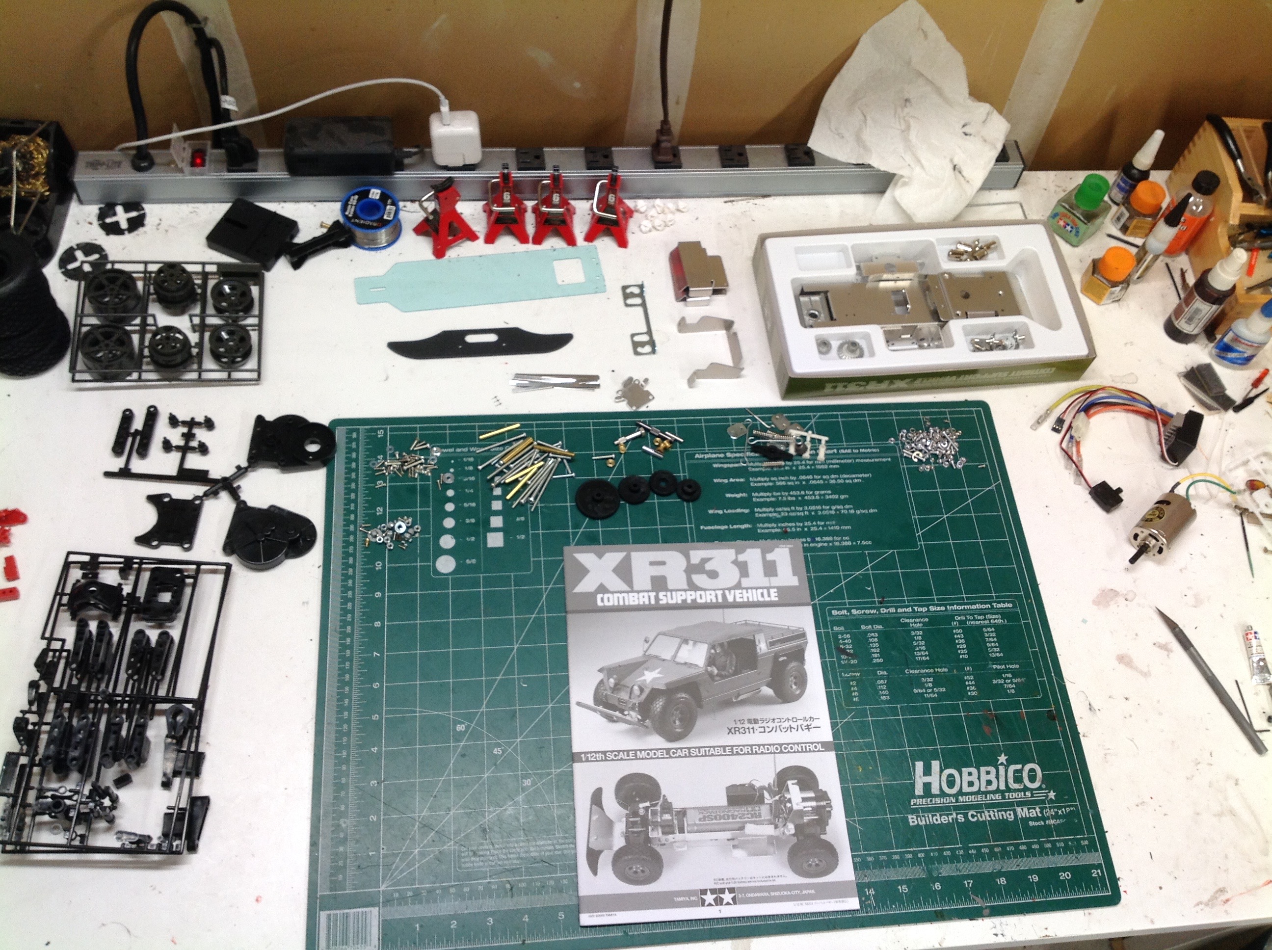
small number of parts for this vehicle. At the time it was made,
the chassis and suspension were very complex but it seems somewhat
simple in hindsight.
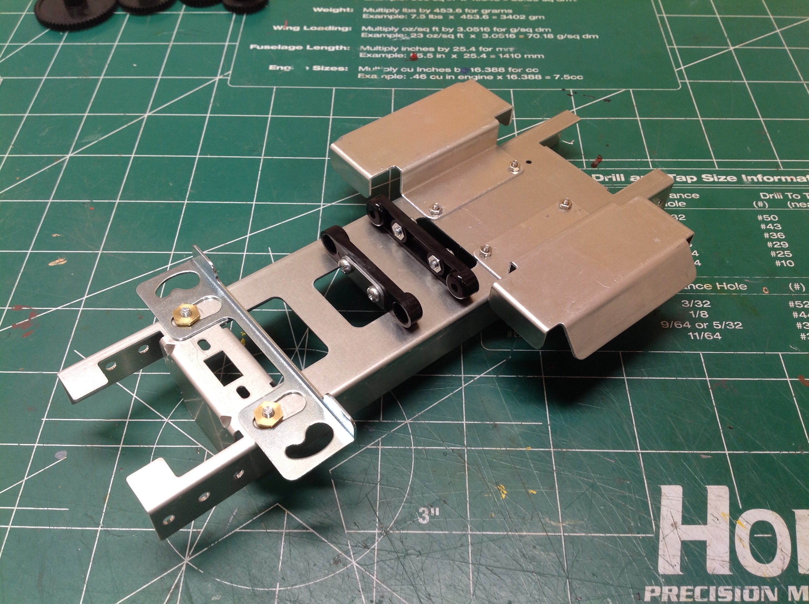
The first step assembles a bunch of metal components which comprise the
bulk of the chassis frame. This picture shows the bottom of the
frame. The bracket you see toward the front with the cam shaped
slots is used to lock on the body. The black plastic parts are the
splined supports for the torsion bars. The rear metal parts are
electronic trays. Much of this is the same as the original, but
the shape of the electronic trays has been updated. The original
were flat (and therefore weak). New electronics are smaller so we
can get away with tubbed trays.
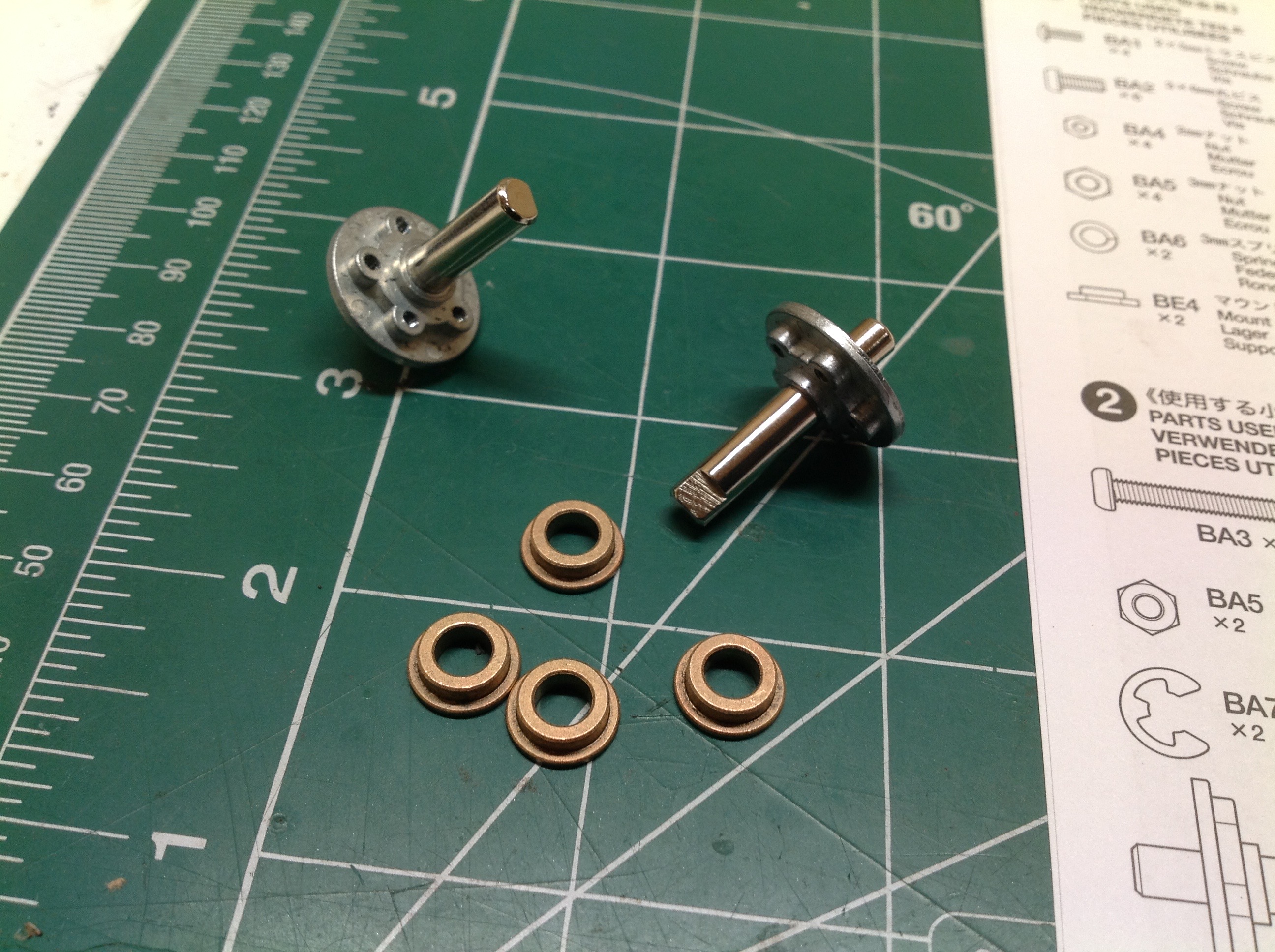
The suspension build starts at the front. The kit comes with metal
bushings throughout. Although I always like to replace these with
ball bearings and I bought a bearing kit from Fast Eddy for this
purpose, the bearing kit did not include flanged bearings so I still
needed to use the kit provided bushings for the front axle.
Normally the axle is fixed and the bearings rotate with the wheel, but
in this case the whole front axle rotates because it bolts directly to
the wheel. The front C-hubs are actually built up from 3 parts as
shown. There is an upper and lower arm with a standoff
between. These clamp around the plastic kingpin of the steering
knuckle. This is identical to how it was done in the original
model 40 years ago.
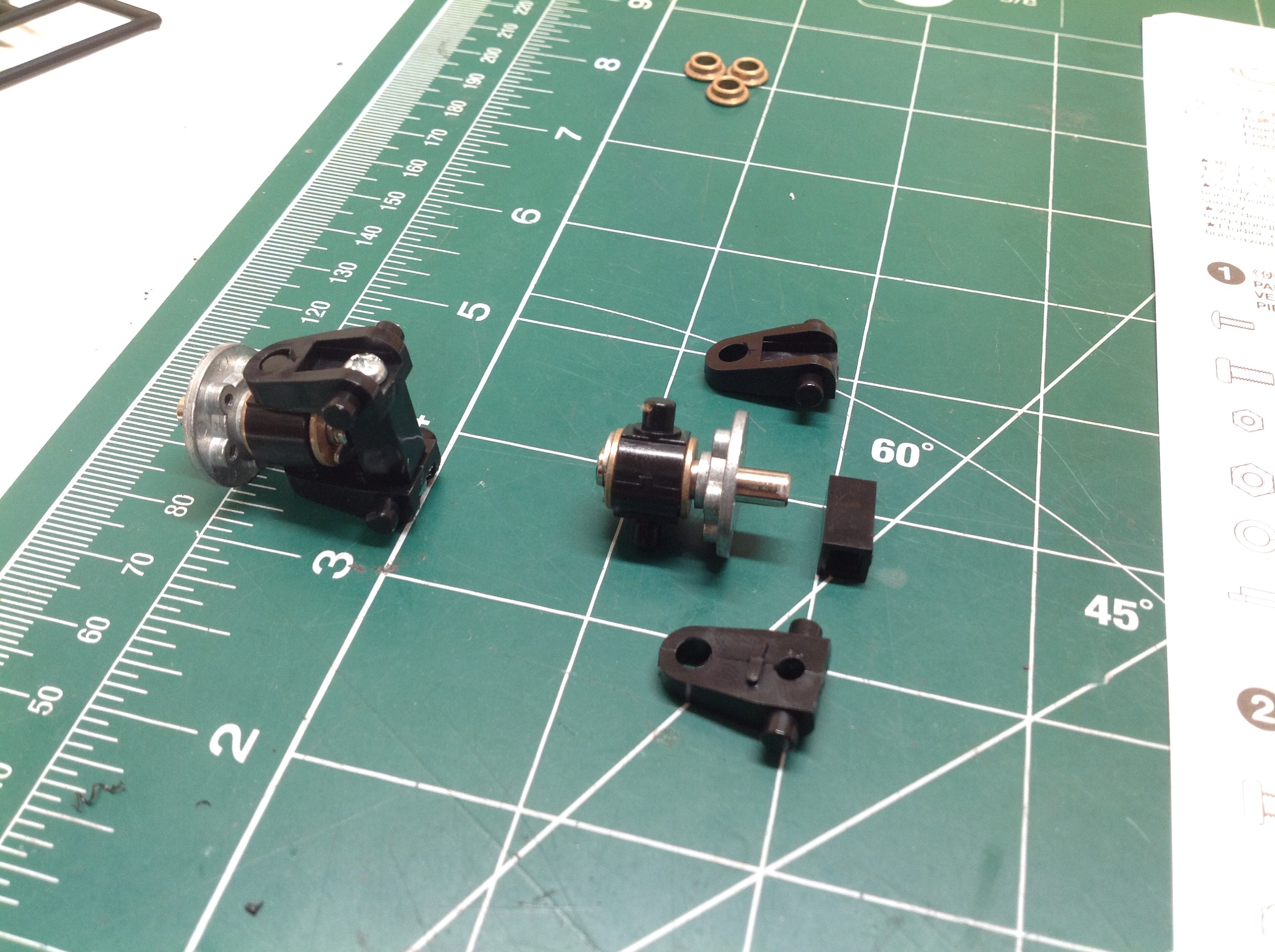
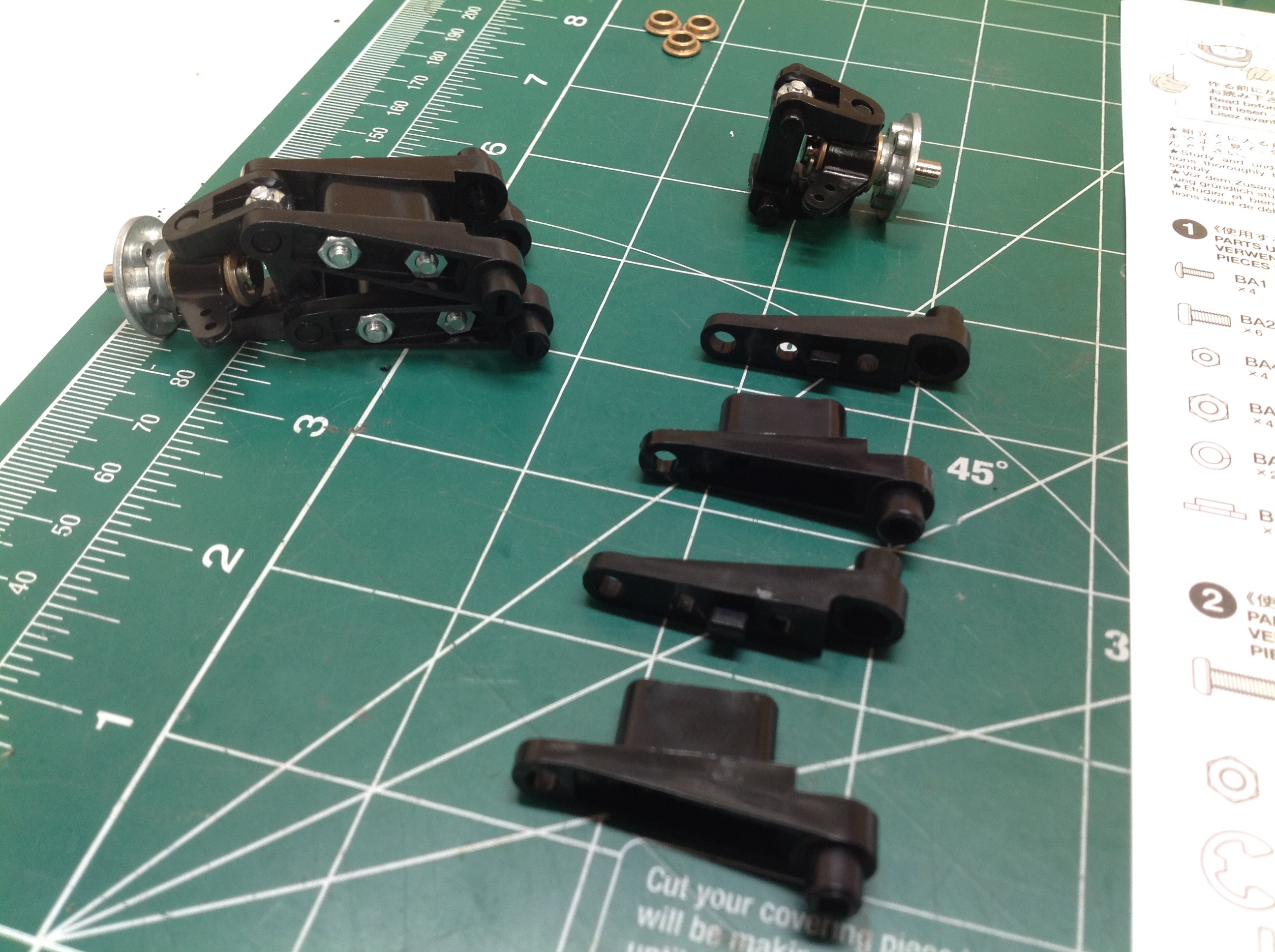
Each upper and lower suspension arm comes in two pieces and clamps
around the C-hub as shown. This setup makes for a lot of little
fiddly parts, especially given that this is a 1/12th scale model.
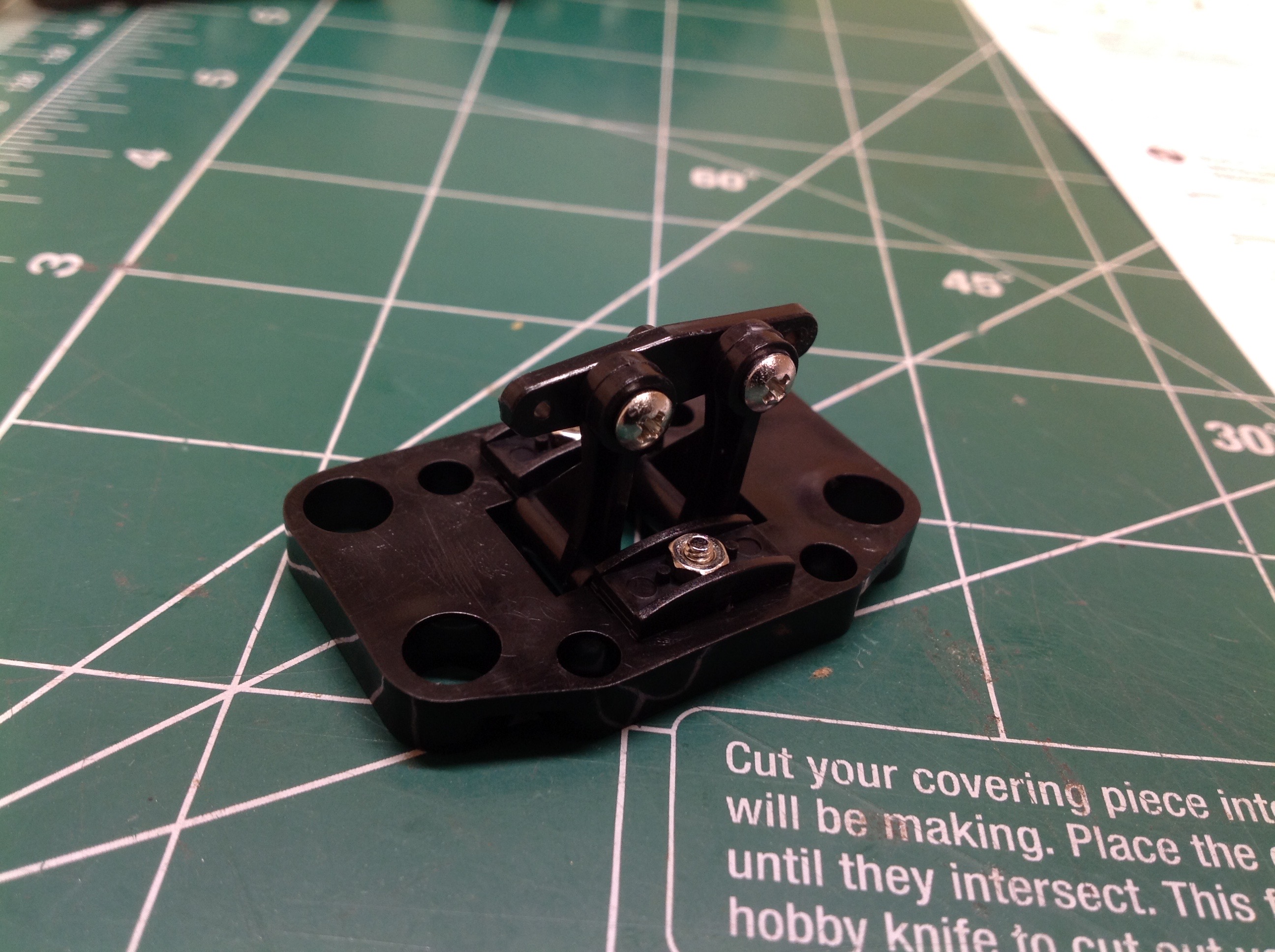
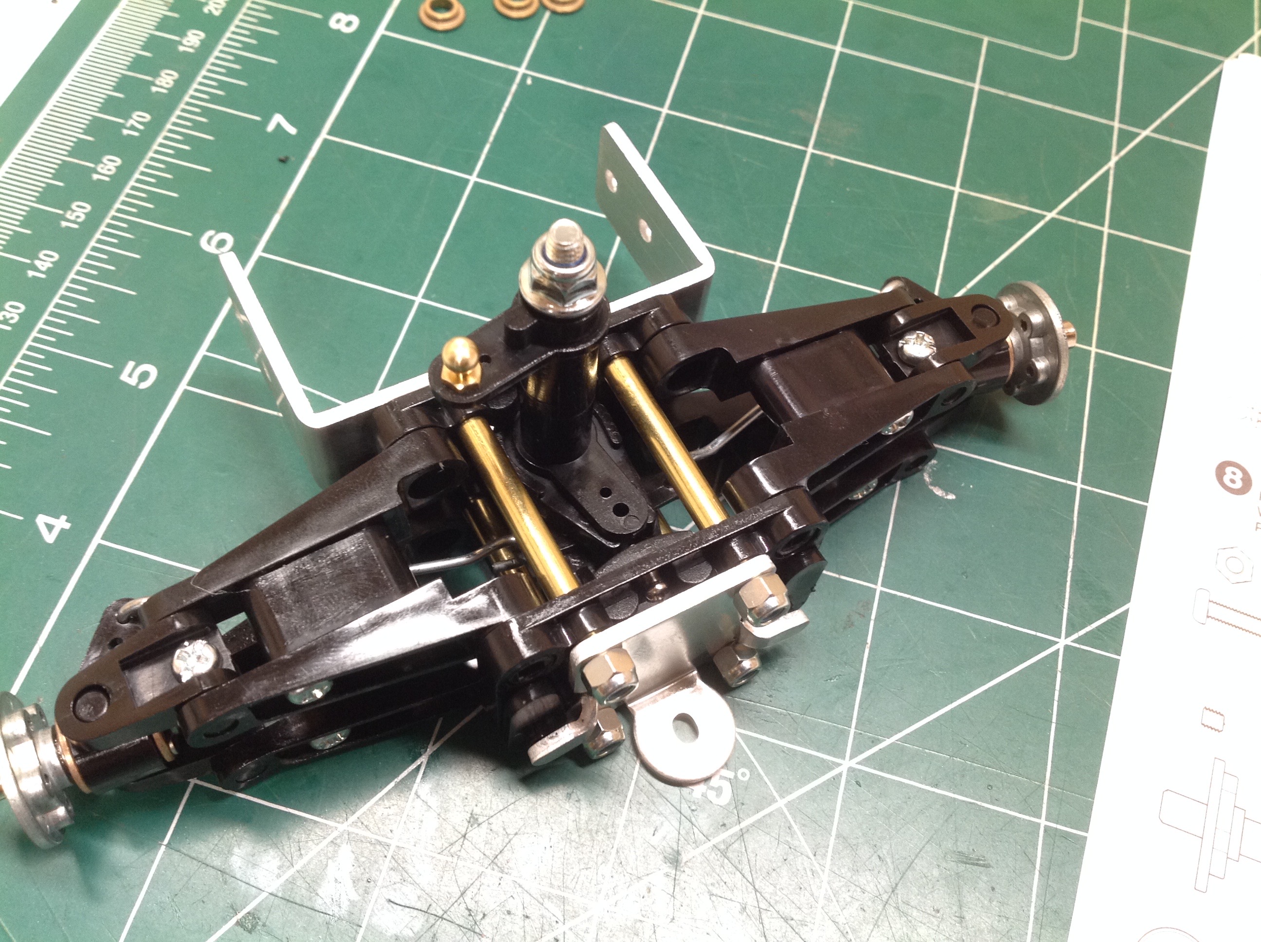
The steering method is fascinating. What you see here is the aft
bulkhead of the front suspension which carries a pair of tiny
bellcranks. The cross bar you see between them has a small stud
protruding from the top. That stud will push on a slot in a
C-shaped clip to move the steering. The flexibility of the clip
acts as a servo saver.
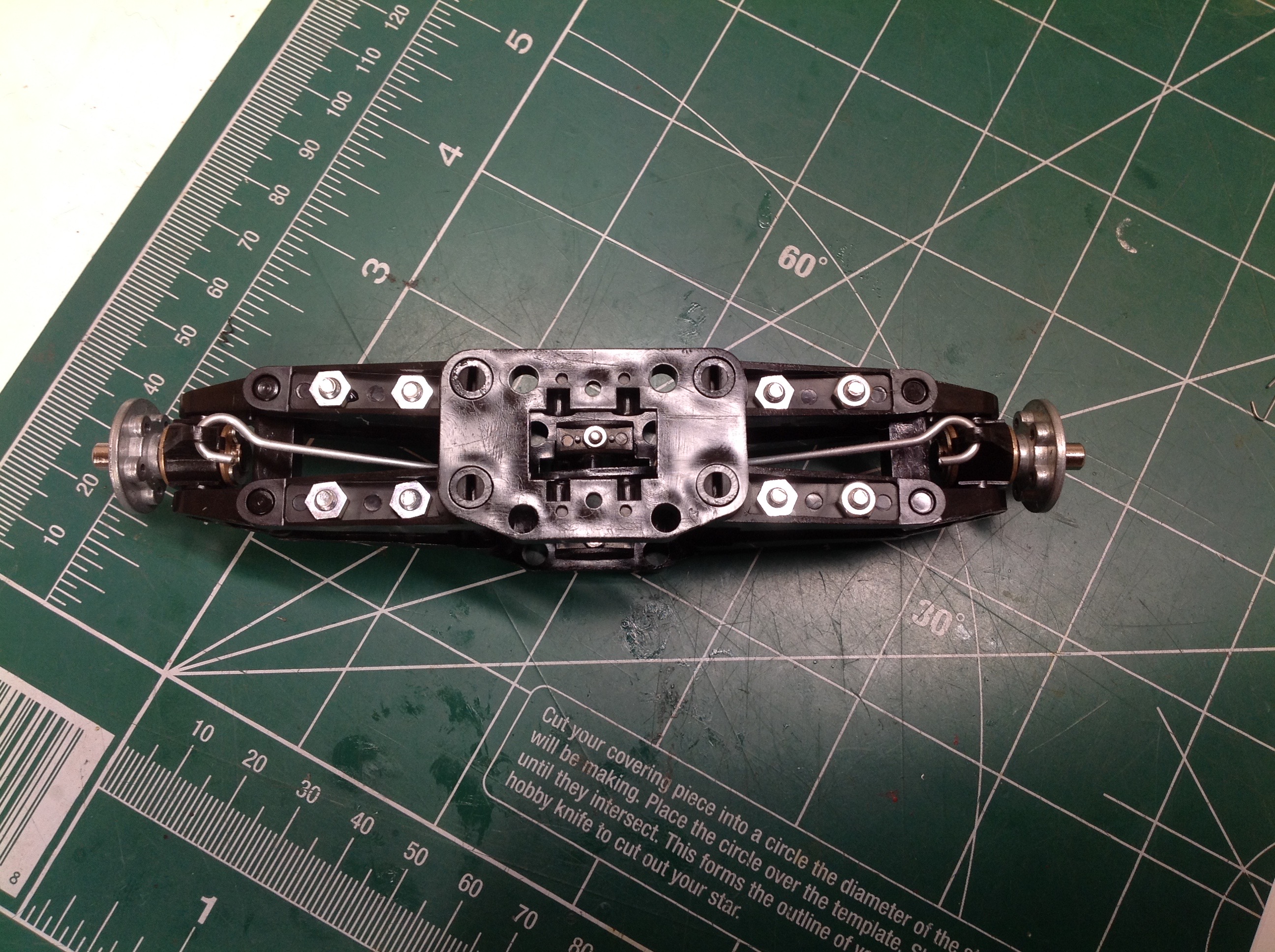
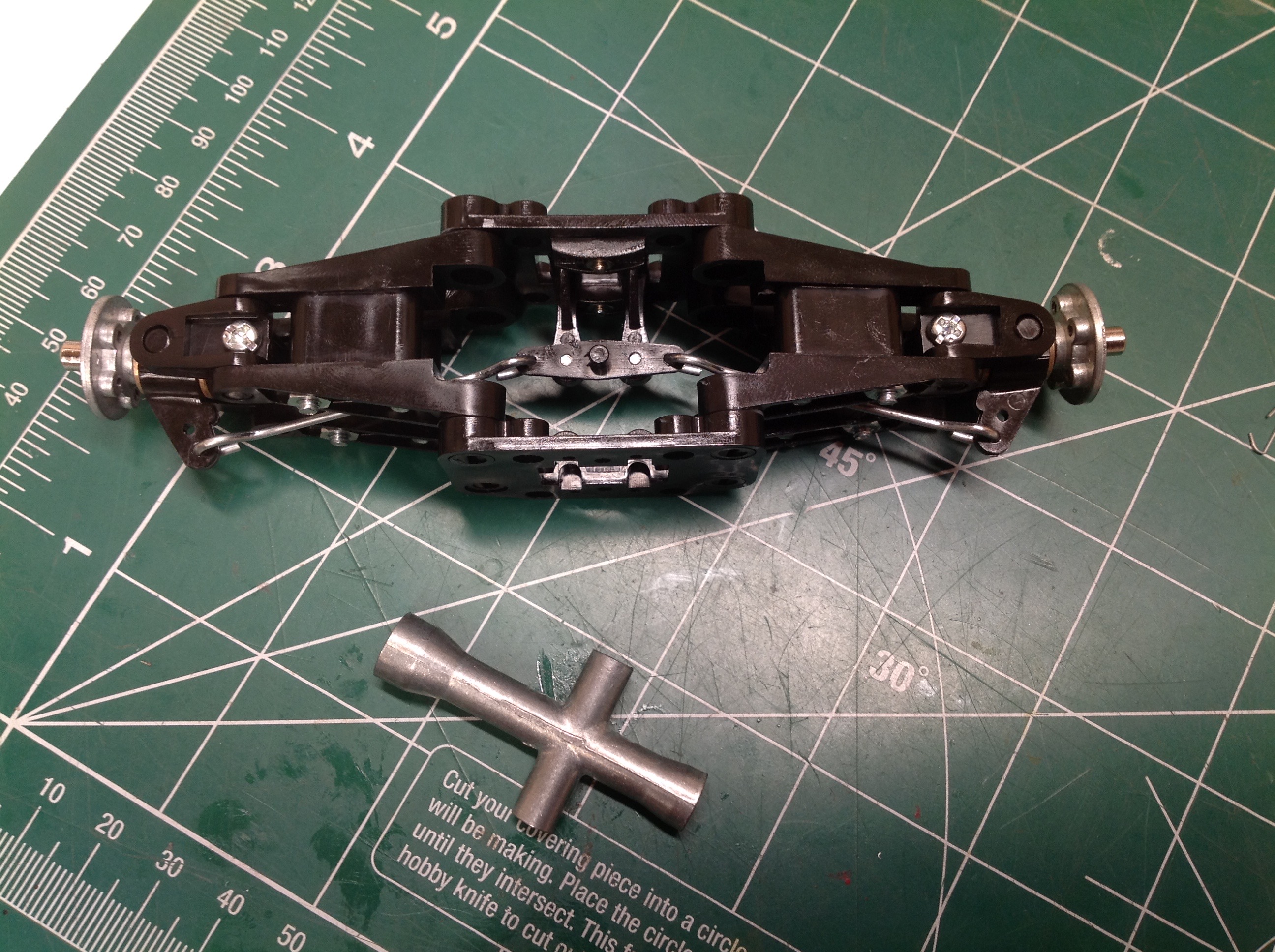
The left hand image shows the front suspension assembly viewed from the
front. The steering tie rods are just wires with shepherd hooks on
the ends as shown. There is therefore no toe adjustability.
The right hand image shows the same assembly from the top. You
can see the two tiny bellcranks and the steering cross bar. The
cross wrench has been added to the picture for scale to show you how
small this suspension is.
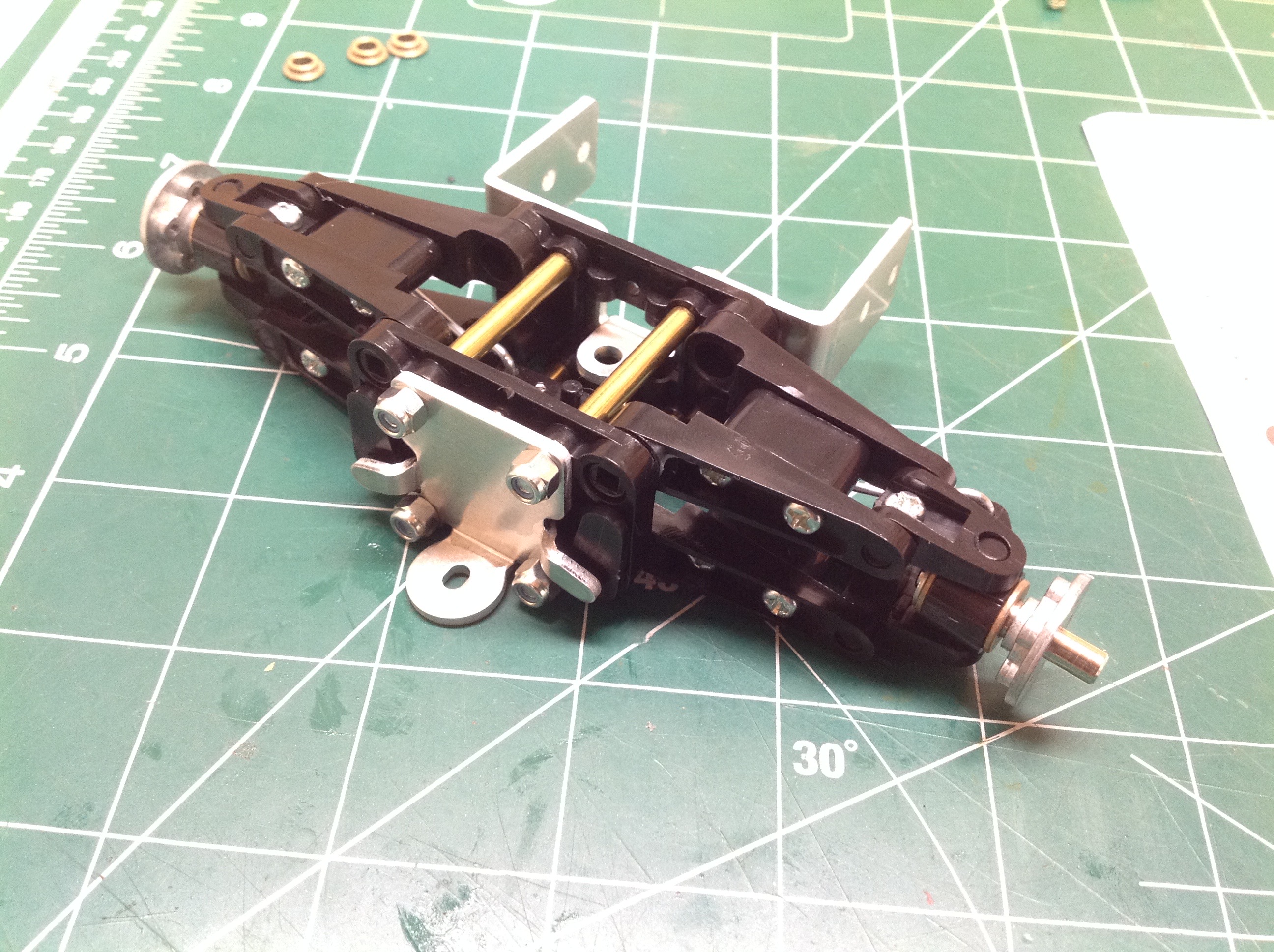
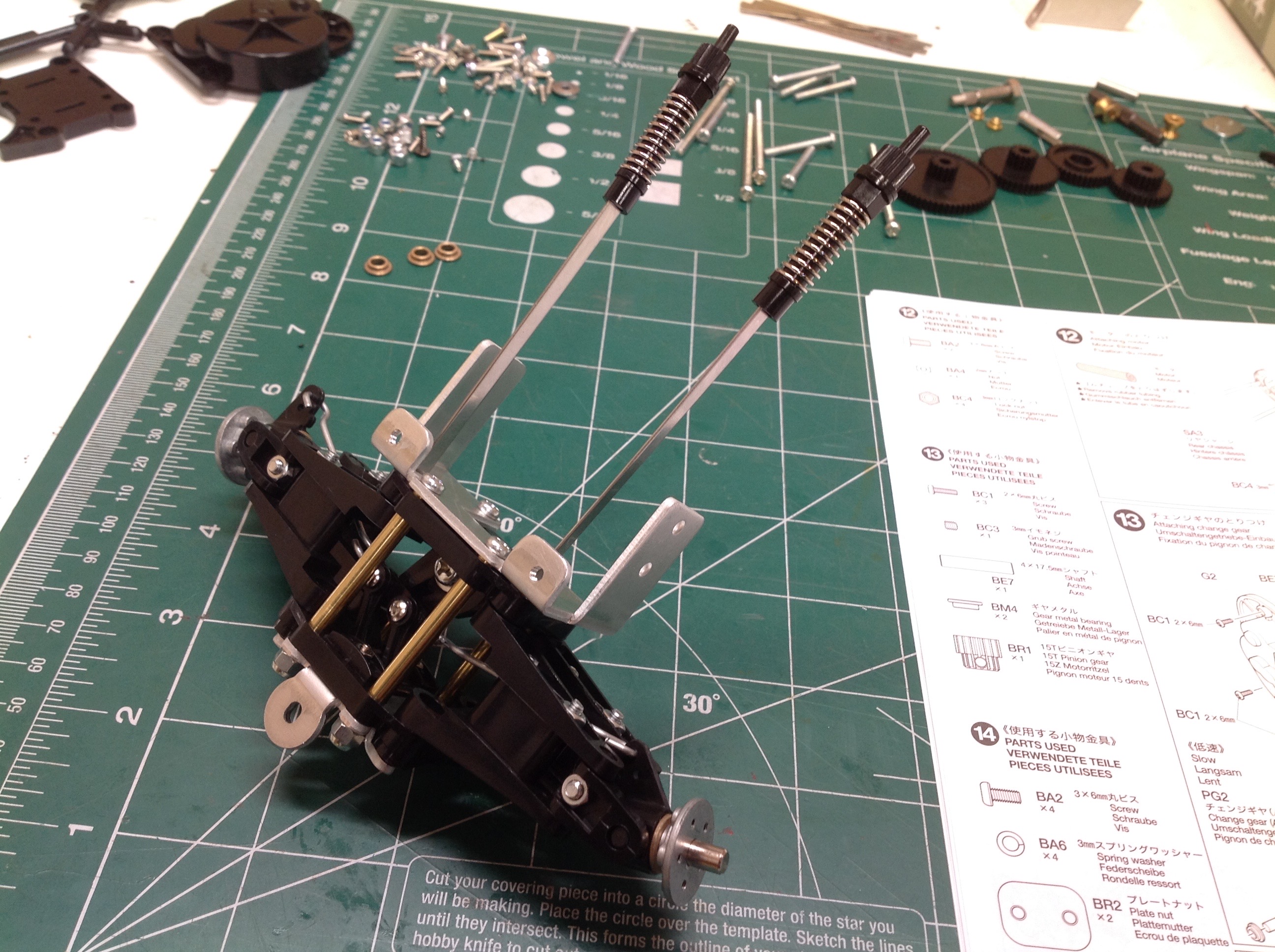
After the addition of a few metal standoffs and a front and rear support
bracket, the front suspension assembly is complete. It is
actually quite complicated. The second image shows the vertical
crank used for steering input.
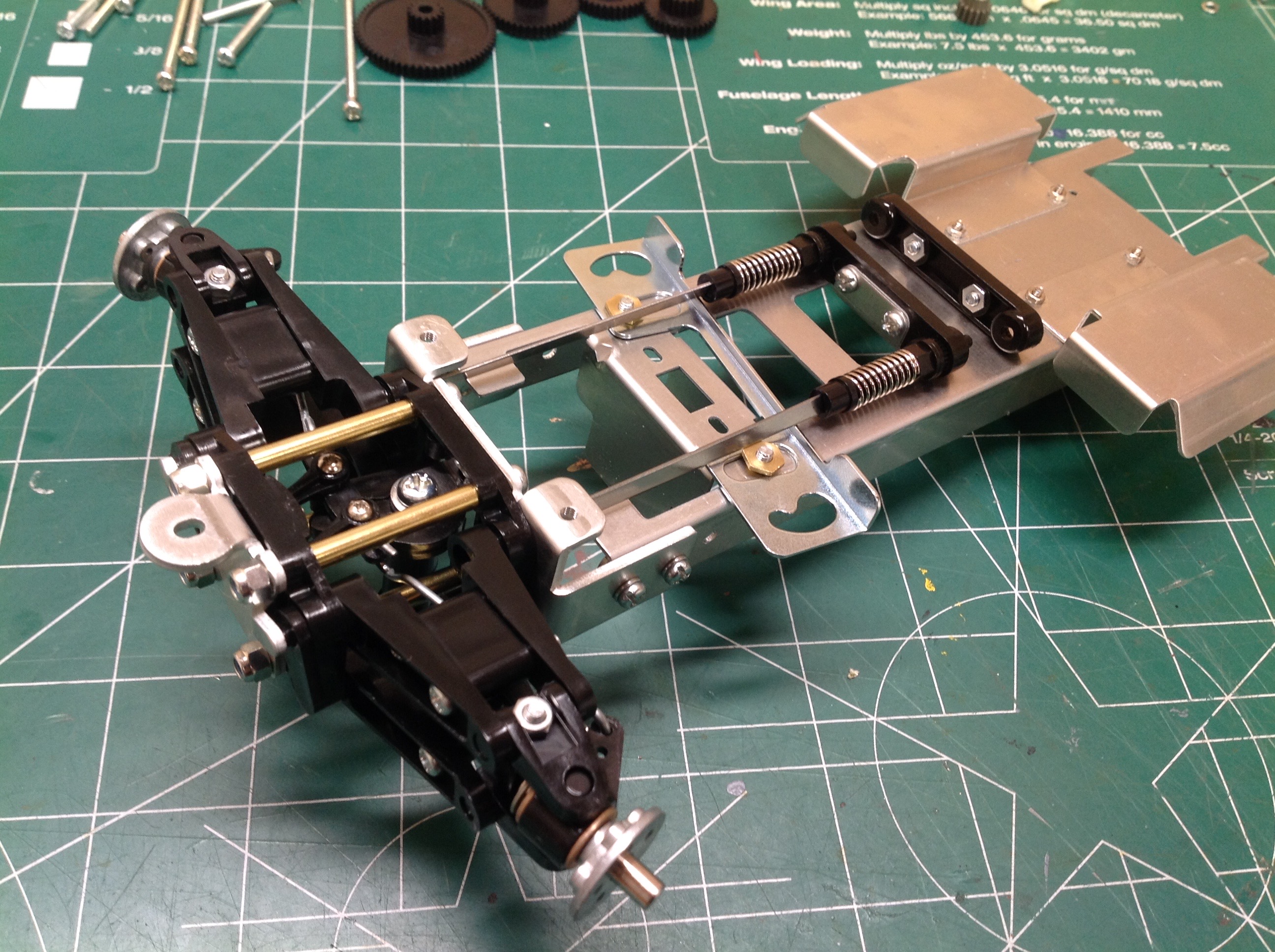
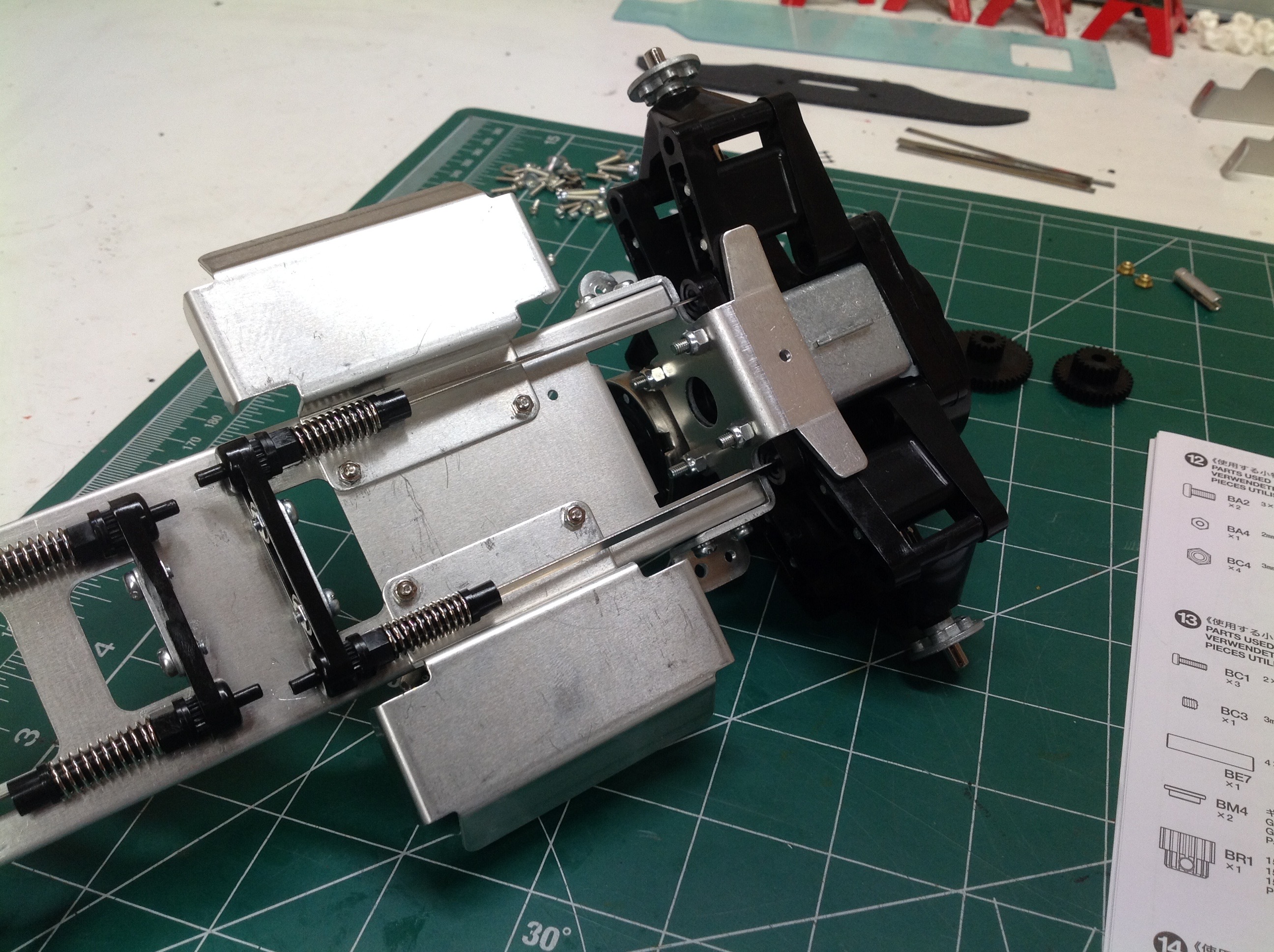
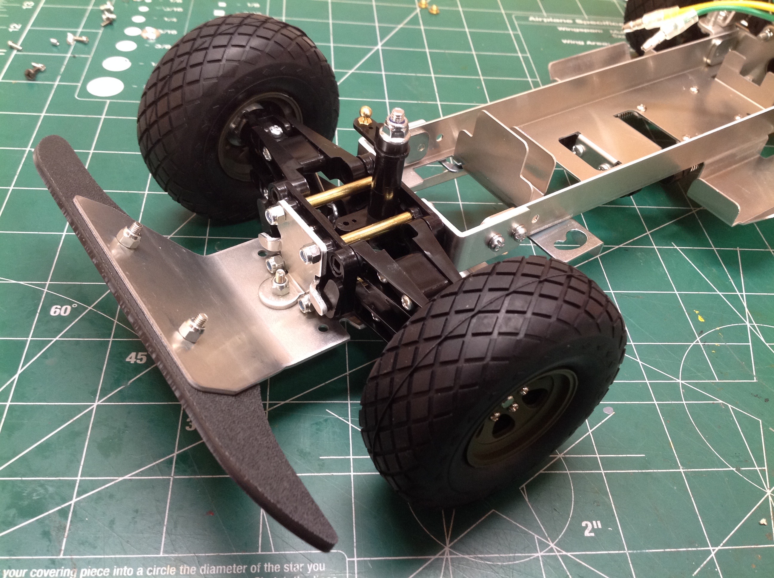
Now the steel plate torsion bars can be installed. These replace
the notoriously fragile plastic bars of the original. The torsion
bars slide into spring loaded supports on the chassis, and into slots on
the lower suspension arms at the other end. As the suspension
compresses, the lower arms twists the bar and that twist is resisted at
the other end. By compressing the spring you can pull the
restraint out of the splined socket and rotate the restraint by one
tooth to add or subtract preload. This allows you to tune the
suspension to vehicle weight. It works really well and allows you
to get a very realistic suspension motion and stiffness.
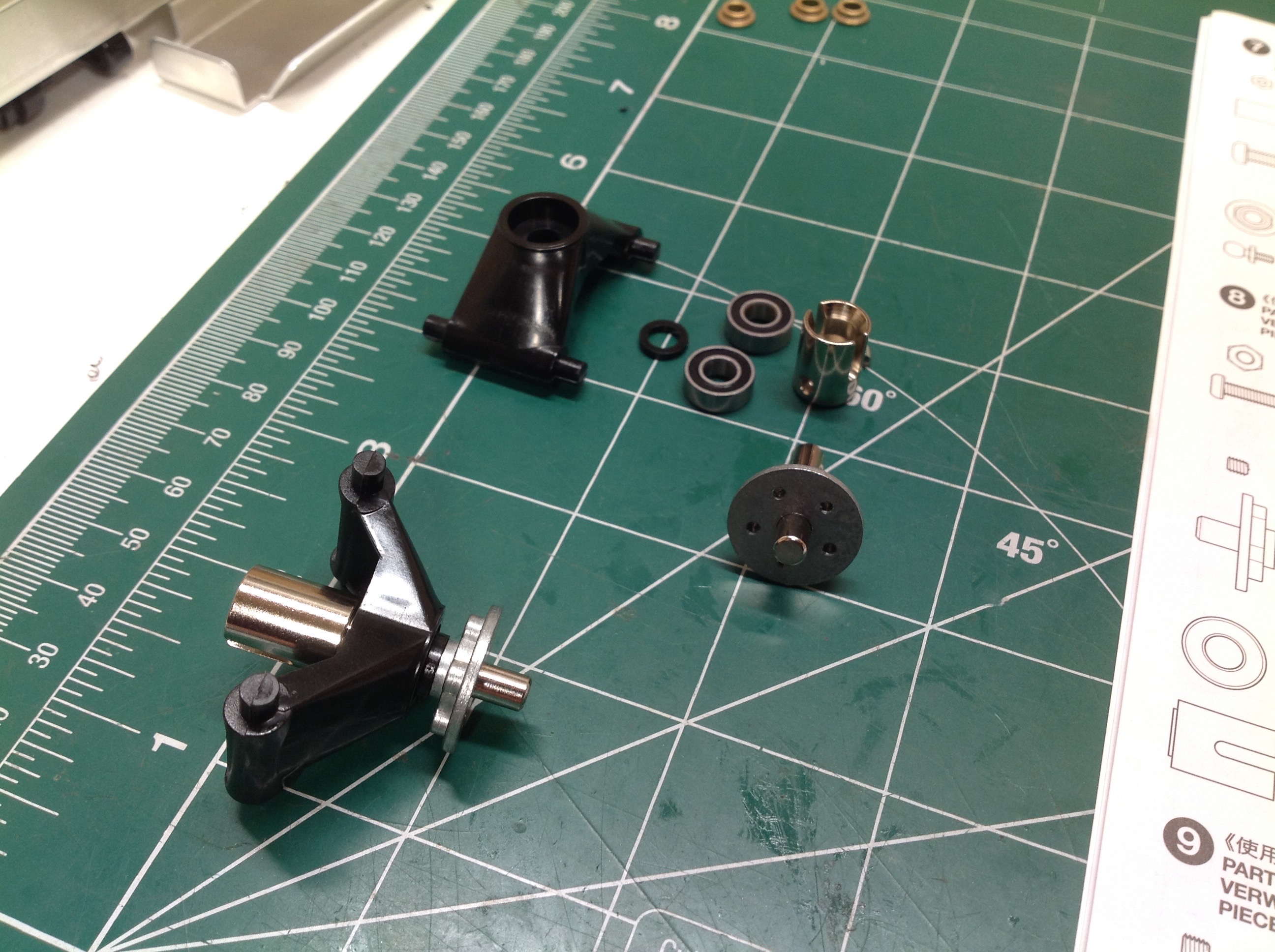
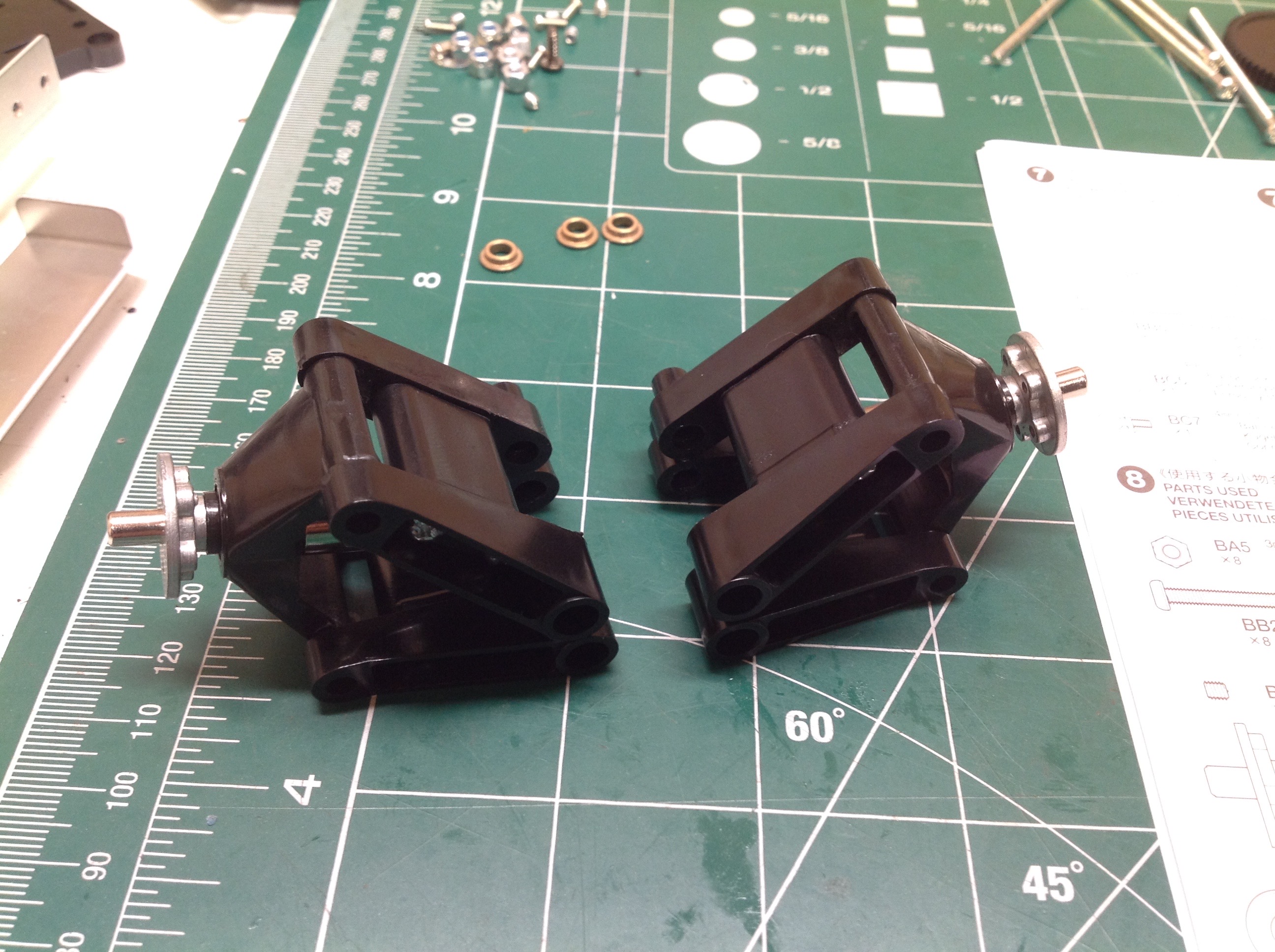
The rear suspension is a bit simpler. The vertical hub is one part
with an axle inserted. I was able to use ball bearings
here. Like the front, the upper and lower suspension arms are two
pieces each. The wishbones are very wide and therefore provide a
lot of support for off road use.
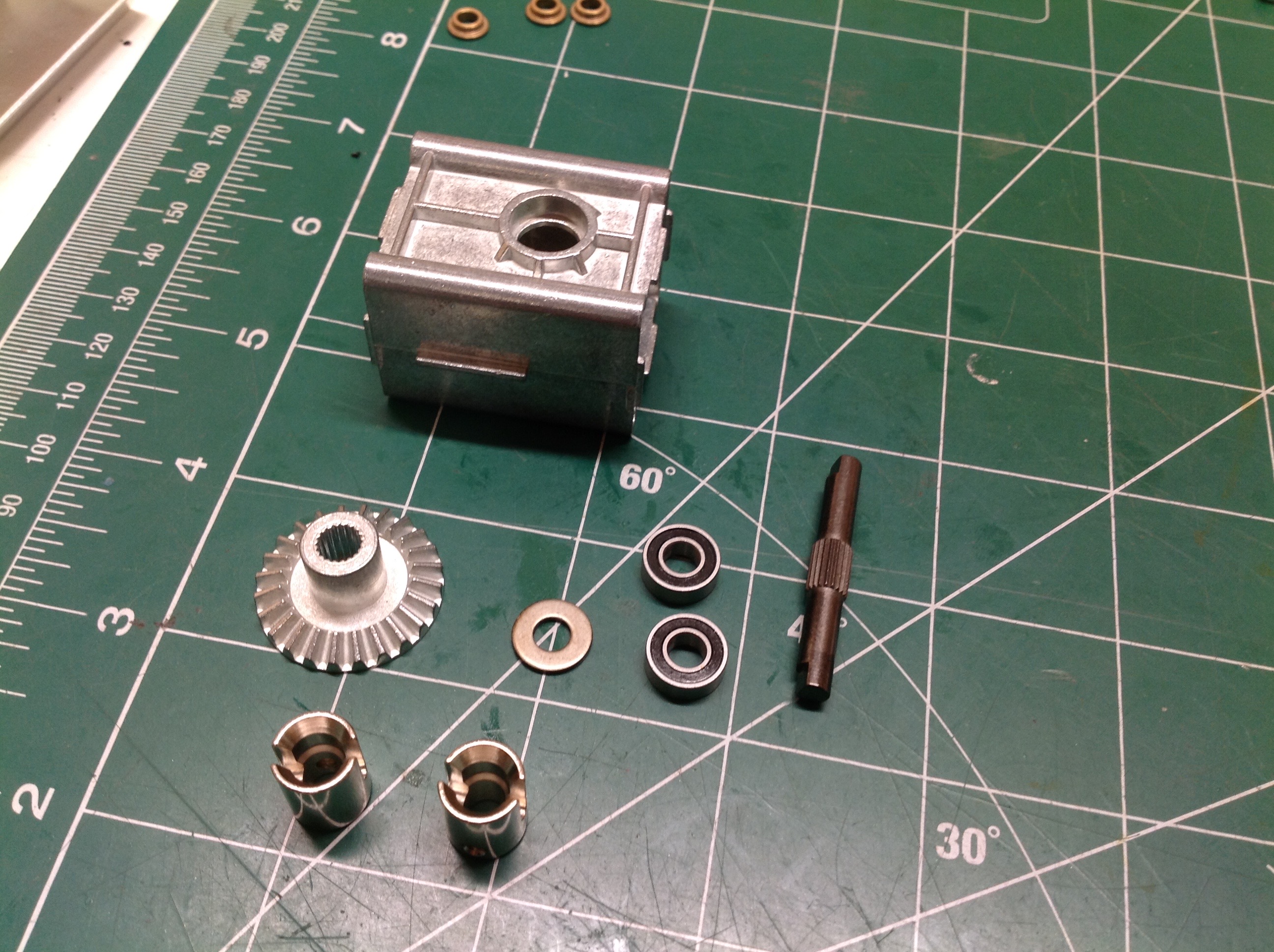
There is no differential on this vehicle. The ring gear is solidly
connected to a drive cup at either side and fit into a cast gearbox
housing. Both ring and pinion are metal. In fact, everything
in these pictures is metal. The original used plastic drive cups.
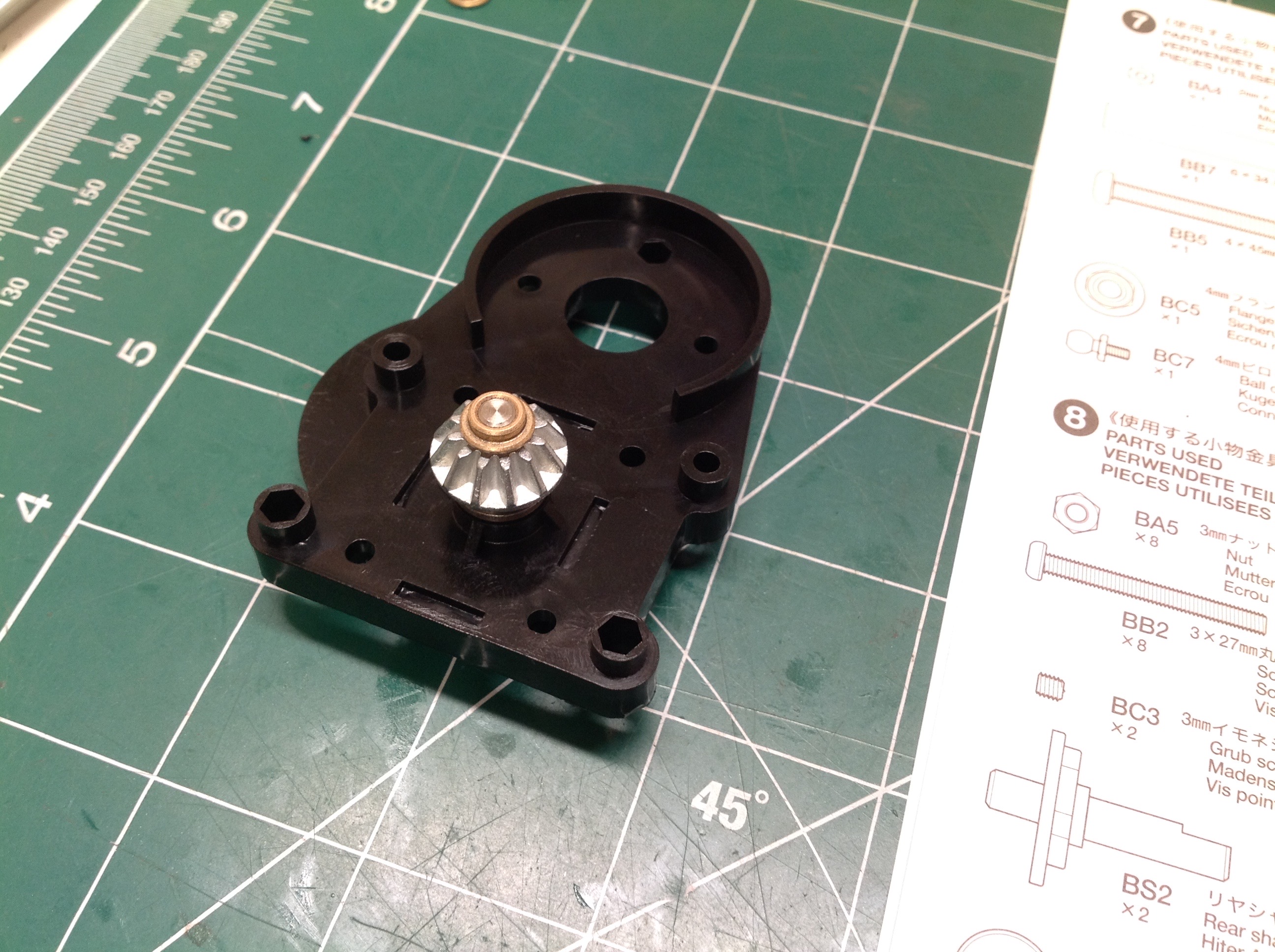
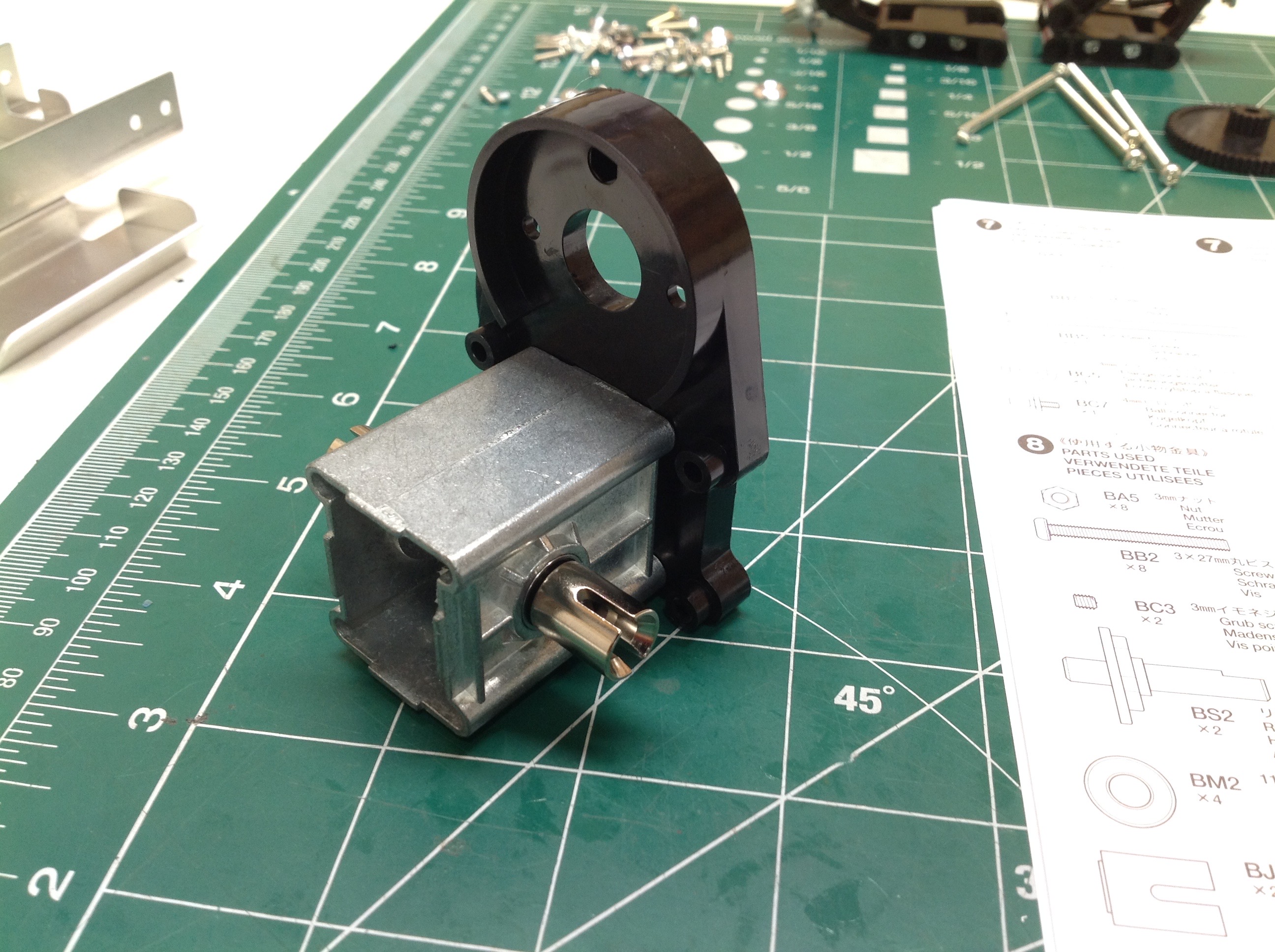
The pinion bevel gear is inserted though the rear gearbox housing
because the motor will drive from the back. This is then bolted to
the main metal housing as shown. You can see another tiny flanged
bushing here that I wasn't able to replace with a bearing.
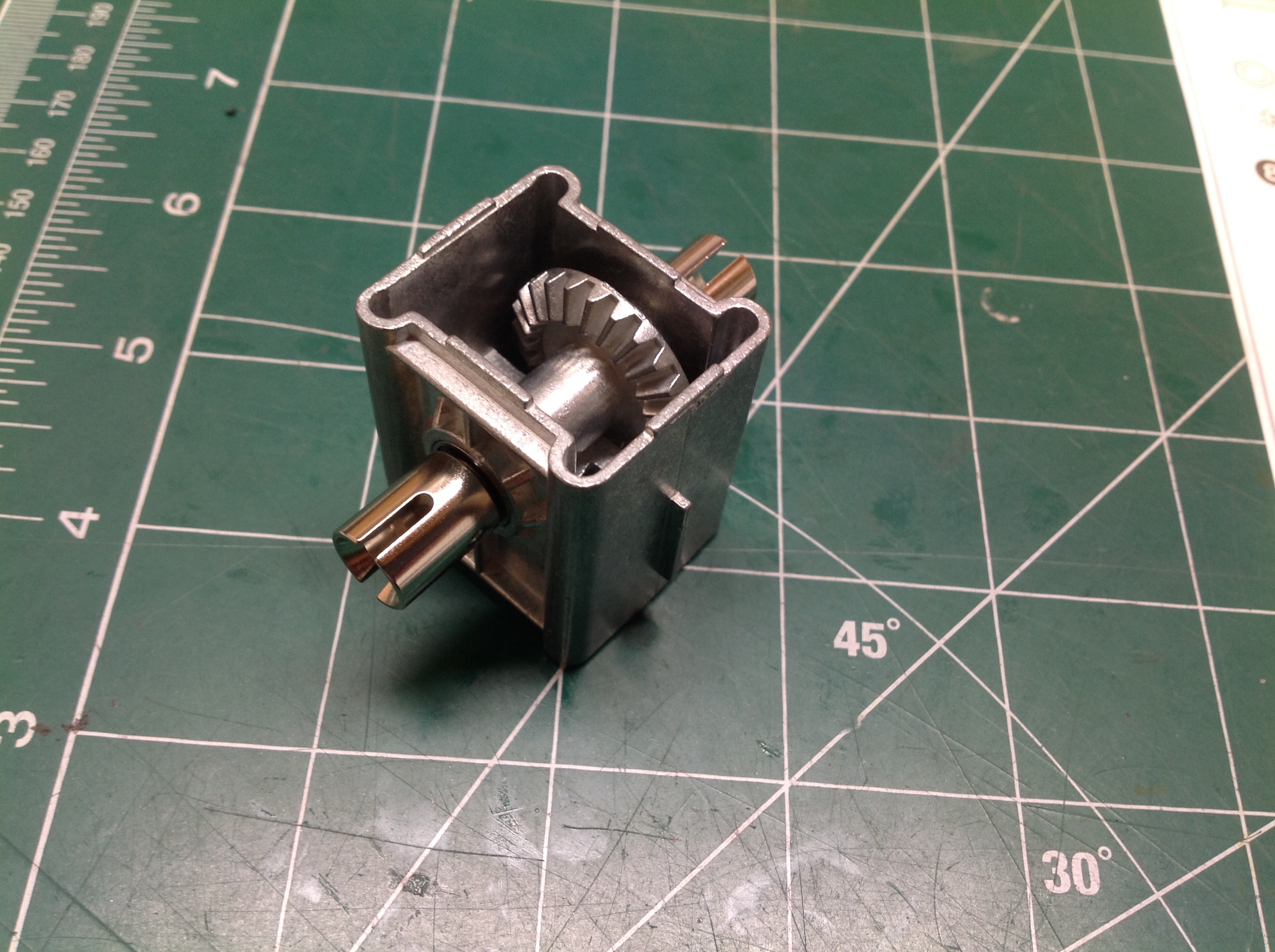
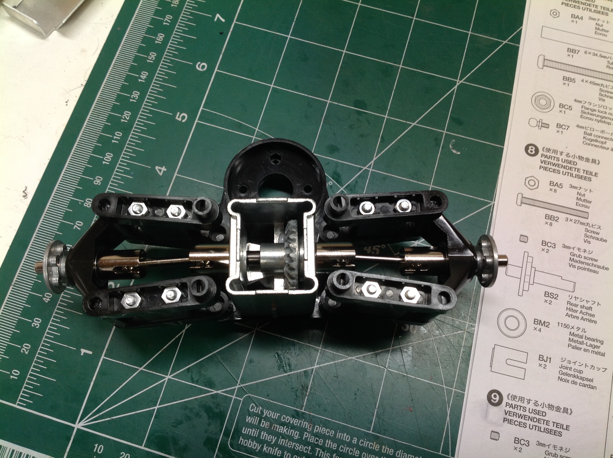
The suspension arms are sandwiched between the front and rear covers of
the gearbox housing. Before the front cover is installed, you can
see the ring gear inside as shown. The bolts used to connect the whole
thing together are the longest 3mm screws I've seen so far (55mm).
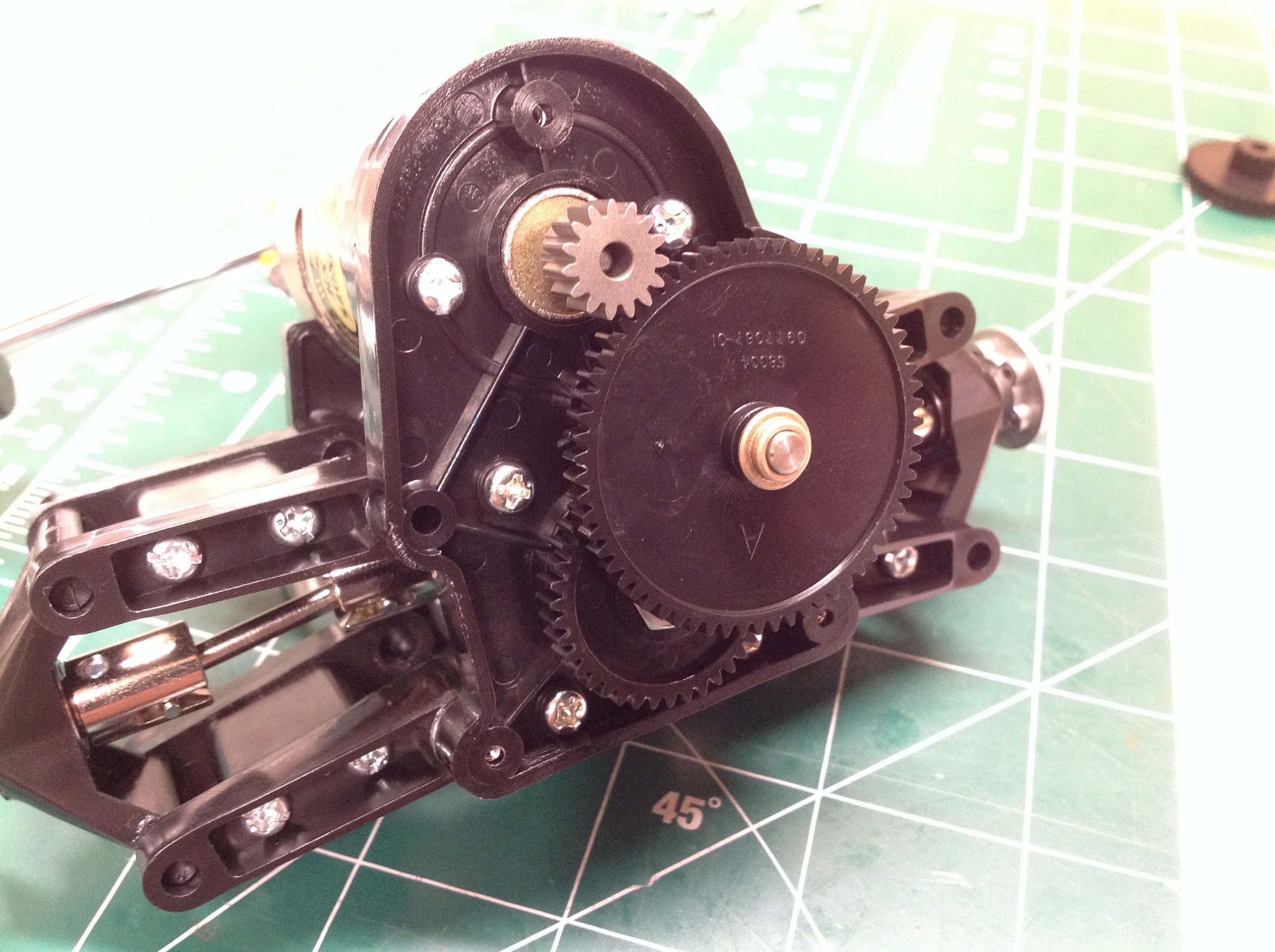
The motor is cradled directly above the rear axle and faces aft.
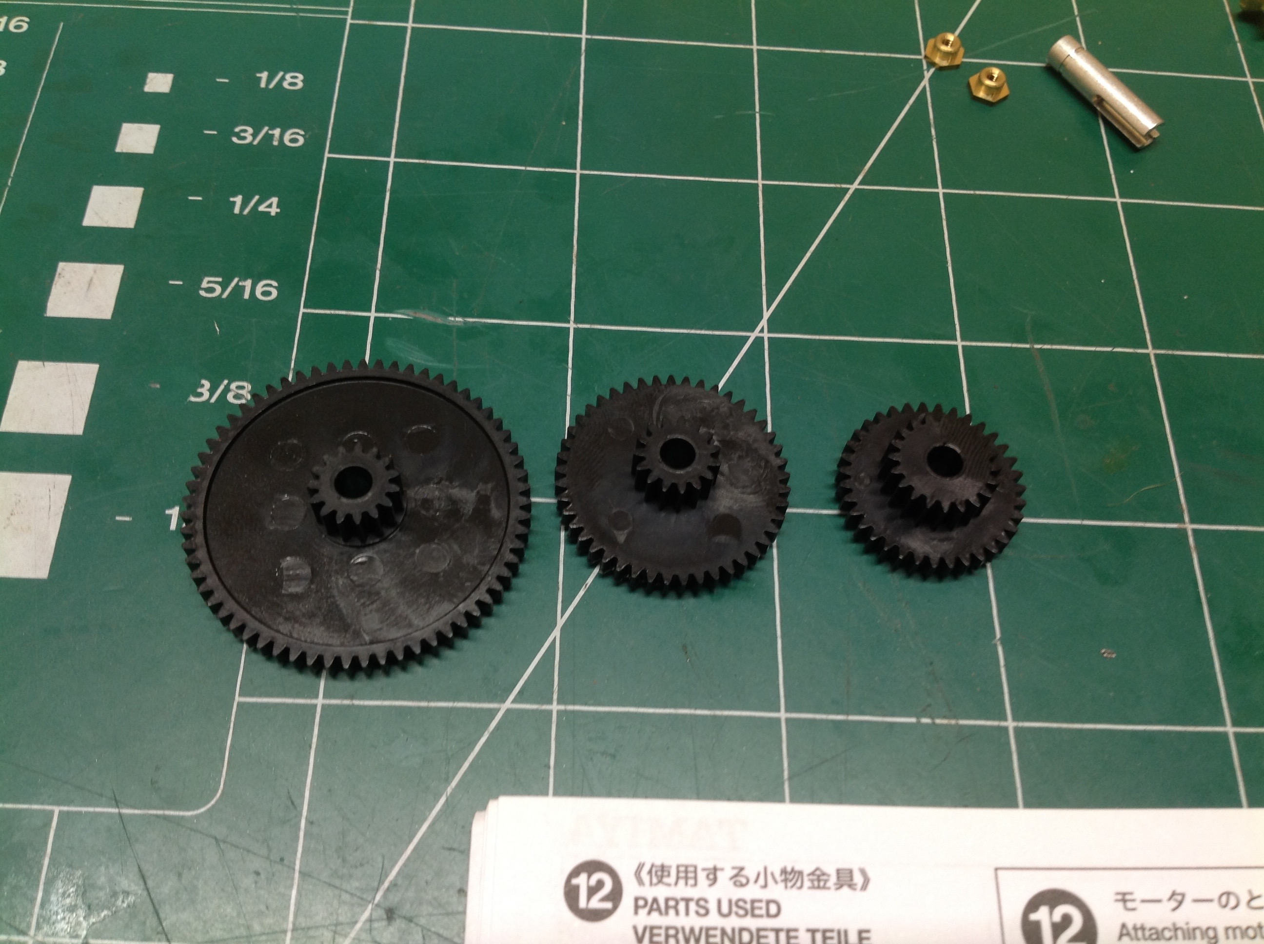
The kit comes with 3 pinion gears which allow 3 different speeds.
They are labeled A, B, and C which are slow to fast, respectively.
Note that the number of teeth on the outside of the pinion are not the
only thing to change. The integral drive gear at the center also
varies. This means that both gear stages are variable which drives
a pretty big difference in available ratios. Let's take a look
assuming a 15 tooth motor pinion and a 40 tooth output drive gear.
The number of teeth is never shown in the instructions so I had to
count them manually. Hopefully I got it right.
- Gear Set A: 63:15 x 40:15 = 11.2:1
- Gear Set B: 45:15 x 40:15 = 8:1
- Gear Set C: 35:15 x 40:20 = 4.67:1
So this shows you that there is a 2.4x difference between the high
and low gearing options. The mesh is not adjustable.
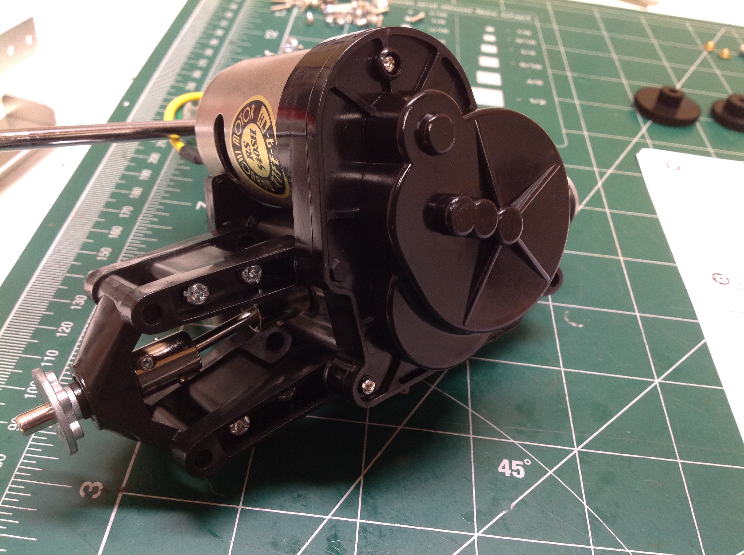
Instead, each gear size fits into a different axle support hole in the
gearbox housing. I'm using a standard silver can 540 motor which
is more than adequate for a model of this size. You wouldn't want
anything more powerful if you want to keep the model intact.
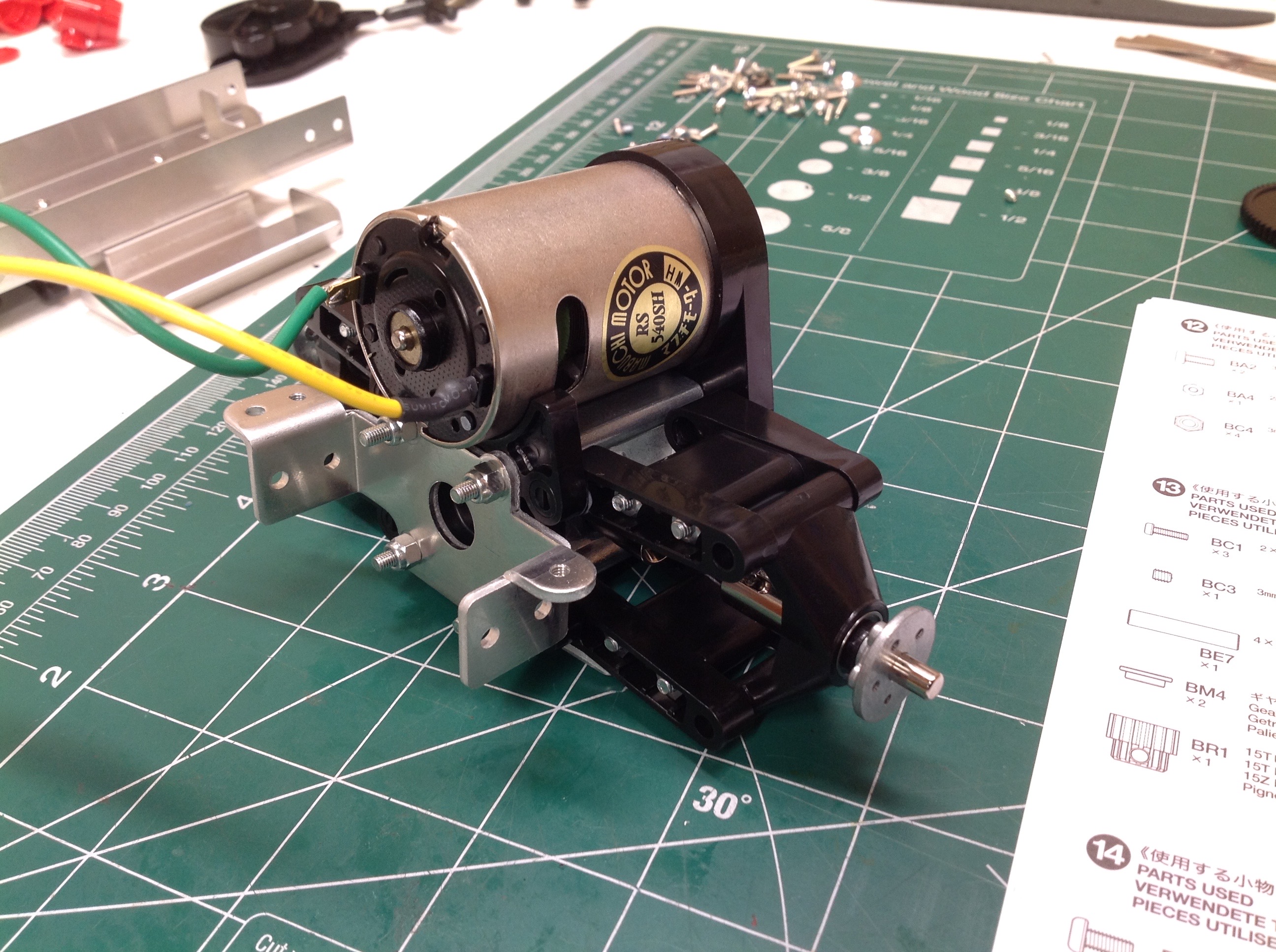
I started by assembling the gearbox with the A gear which is the slowest
speed (highest gear reduction). The motor pinion is aluminum but
the A gear and the drive gear are plastic. As previously
mentioned, the ring and pinion of the locked axle are metal. Once
the plastic cover is installed as shown on the right, you can see the 3
round blisters which represent the bearing supports for the 3 different
gear sets. They are arranged in an arc with the motor pinion so
they will all mesh without any adjustment. It is a clever and
reasonably fool proof system.
The rear torsion bars are installed just like the front but must be
preloaded quite a bit more because of the weight of the motor in the
back. Don't forget to install the battery before adjusting the
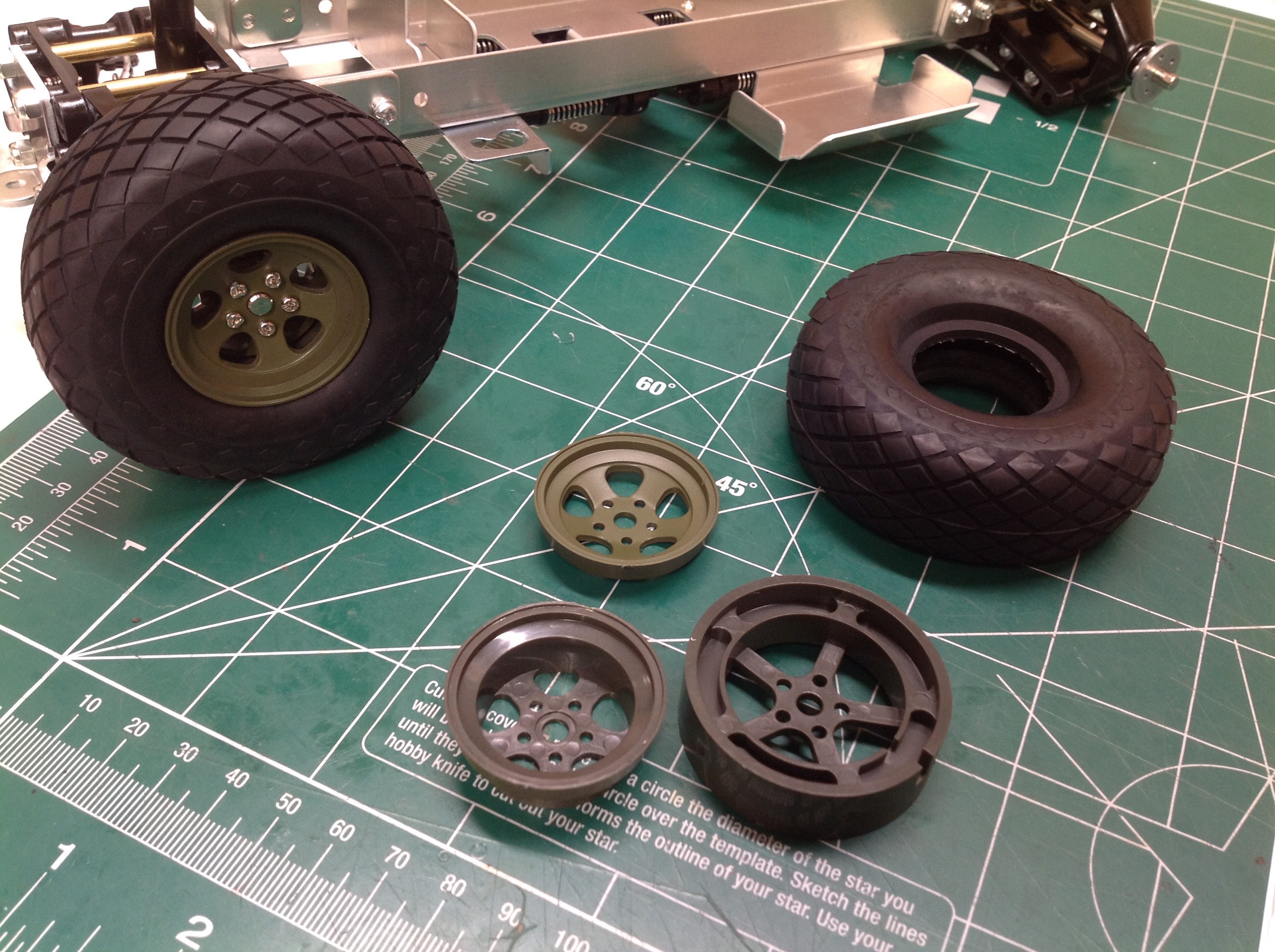
preload because it is a huge component of the overall weight. The
wheels are a 3 piece design which must be assembled directly to the
axle. There is no way to remove the wheel without also taking it
apart. It is not exactly a beadlock since it doesn't clamp tight
on the bead, but it does provide good support and, most importantly,
eliminates the need for tire glue. I love the profile and tread
pattern on these tires.
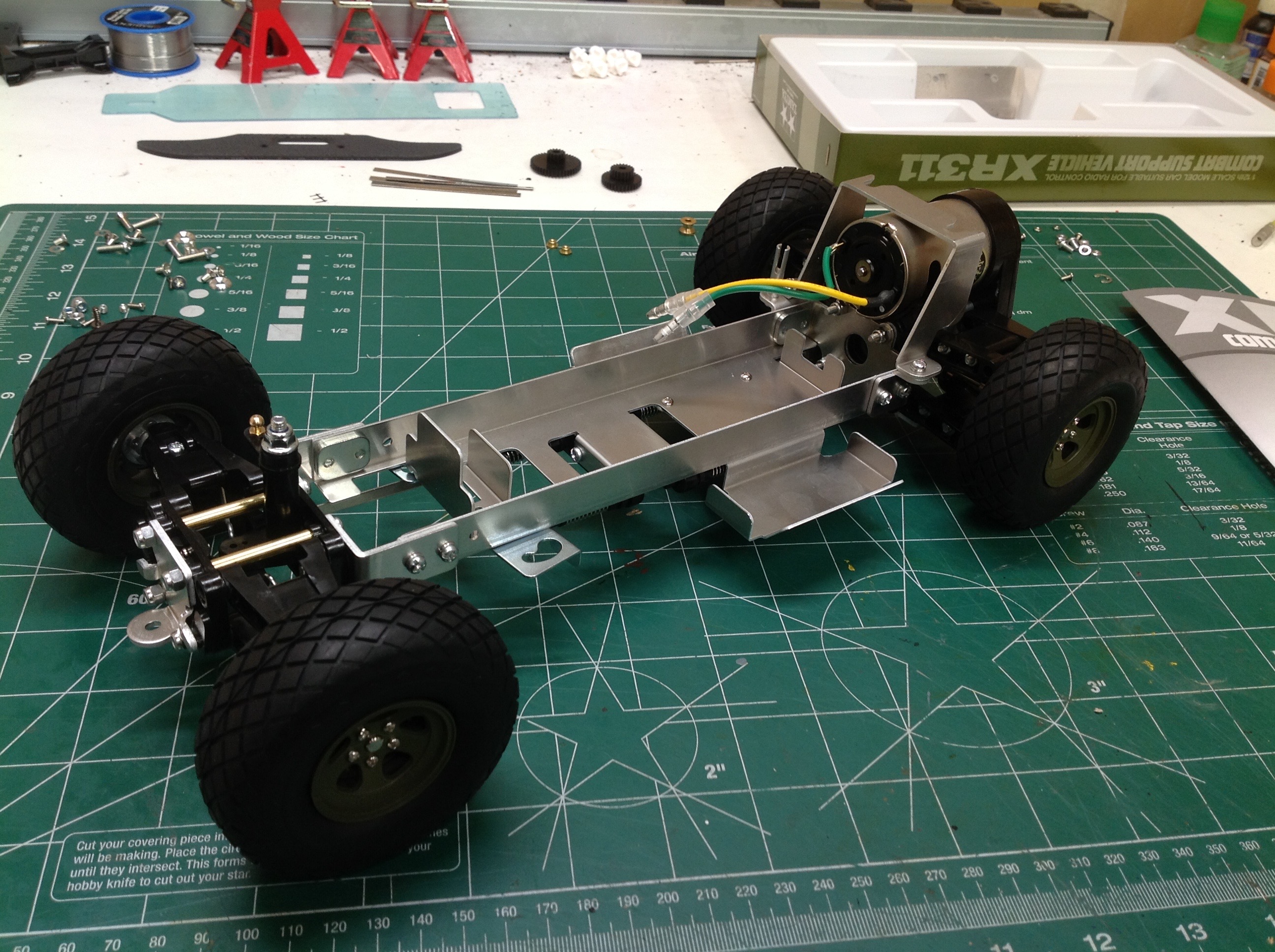
Here's the completed rolling chassis. Note that everything between
the axles is metal. The right hand image shows the installation
of the durable front bumper. There's really not that much going on
here mechanically or structurally, but the model is very sturdy.
The same can't be said for the body.
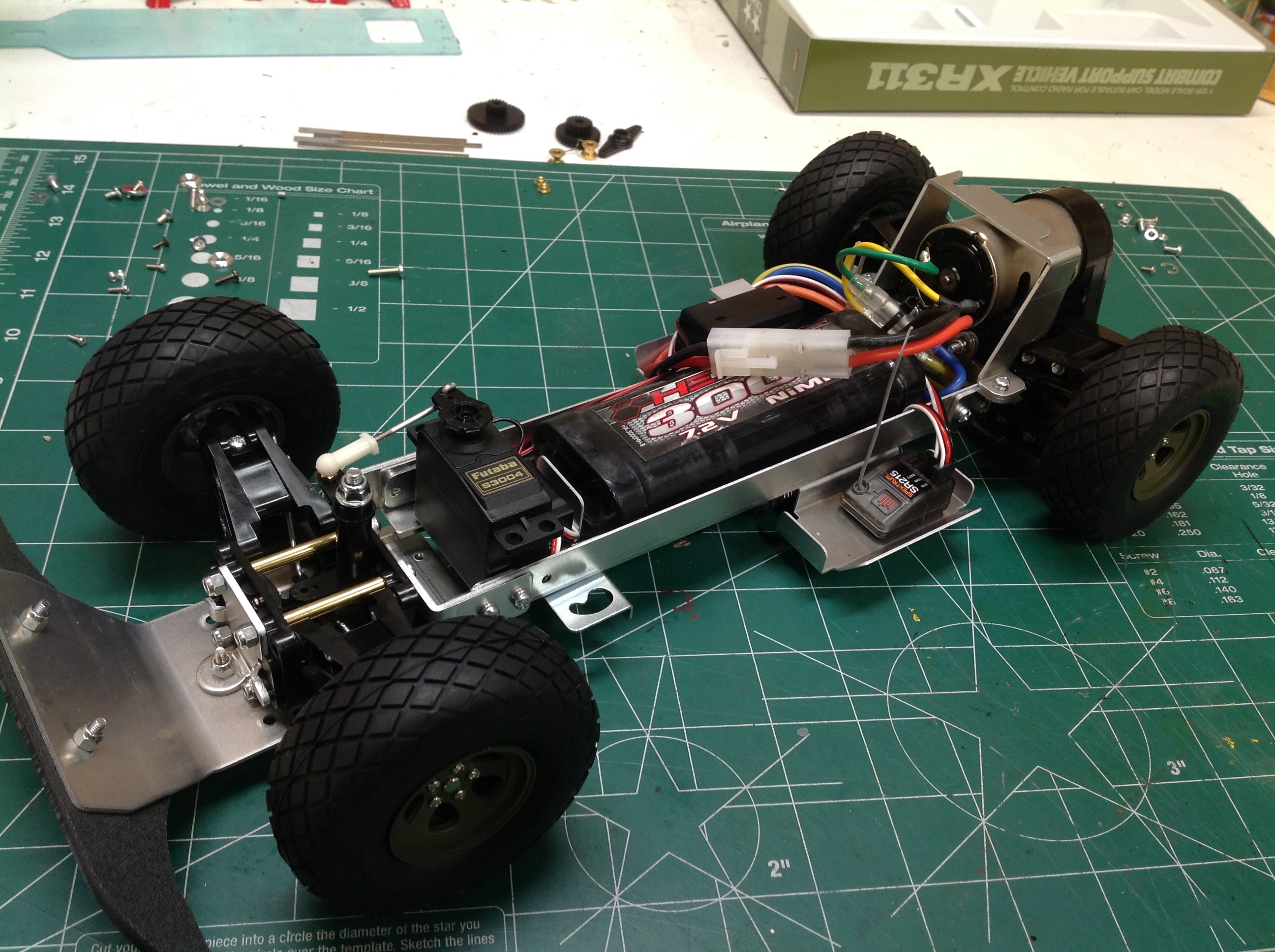
The original needed to make room for both a steering and a throttle
servo as well as the associated MSC, but we have more space to play with
here. The steering servo attaches up front with servo
tape and is connected to the steering crank with a short rod. The
rest of the main tub leaves room for a standard 6-cell battery
pack. The trays to either side have plenty of room for an ESC and a
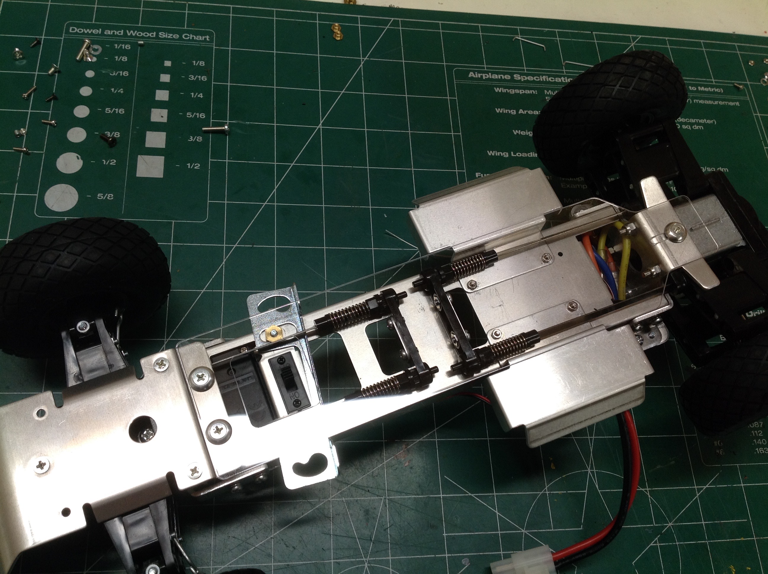
receiver. The last image shows the completed chassis from
below. Barely visible is the clear under tray which protects the
torsion bars from obstacle contact.
©2019 Eric Albrecht