Tamiya TRF 421 Project
Page 2: Assembling the Chassis
While writing about this build, I am going to concentrate on the
differences between this and the last chassis in the TRF line I built
(the TRF 420X).
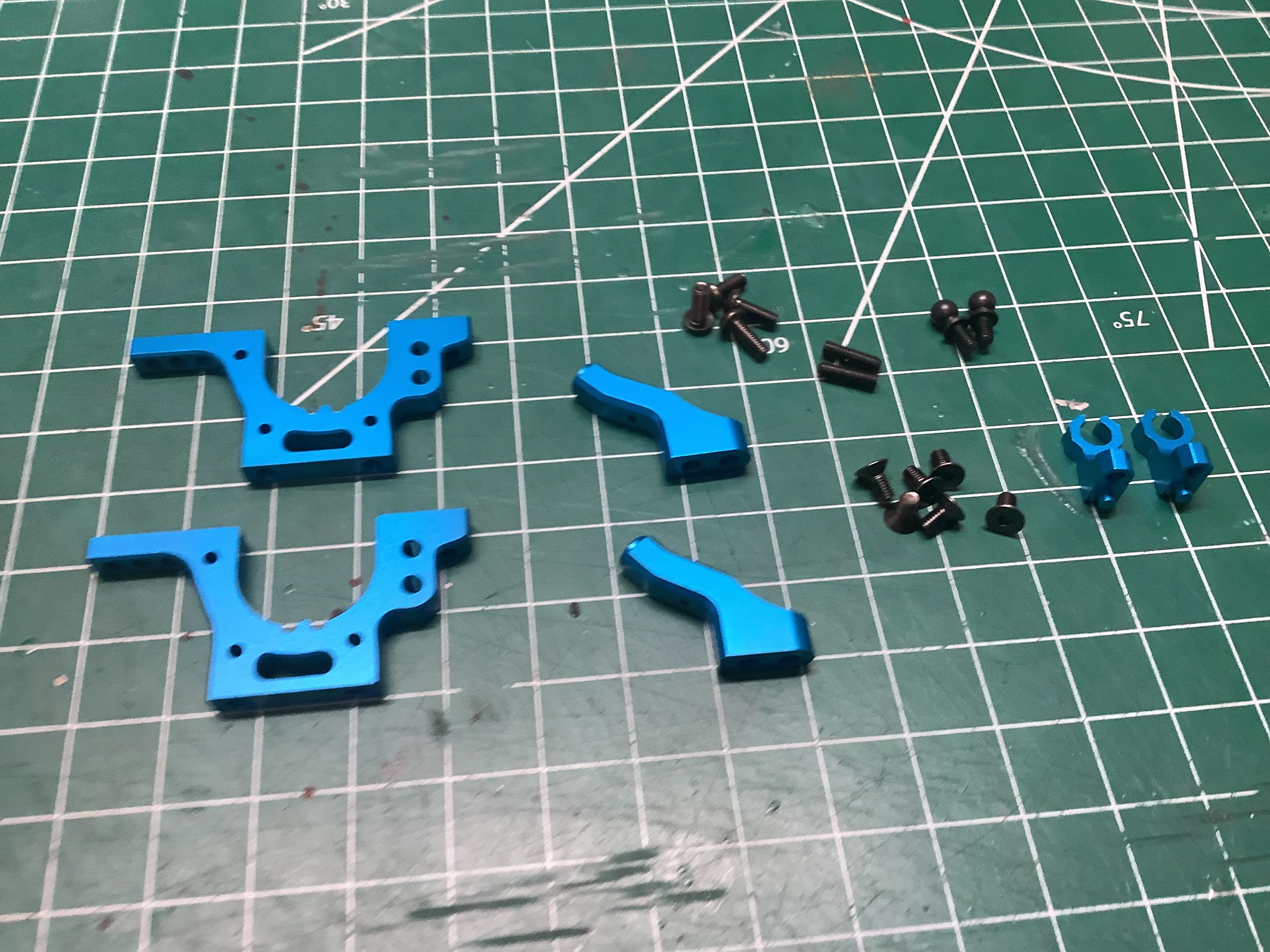
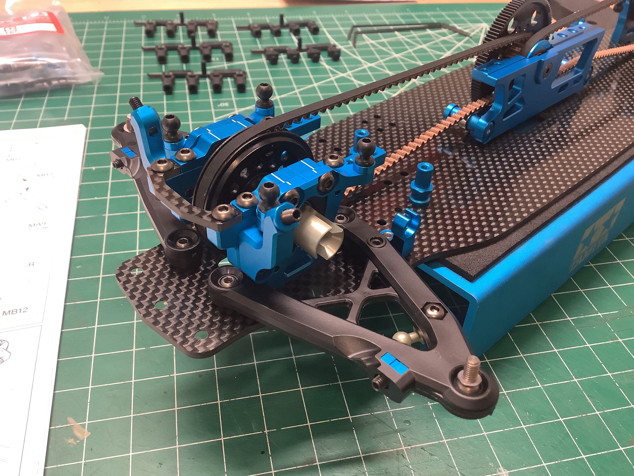
One of the things I noticed when starting Step 2 was that all four
bulkheads are identical (Step 1 is charging the battery). This is
nice from a spare parts point of view (though I don't ever expect to
need one), and also makes it nearly impossible to screw up the build by
using the wrong one. On the right I've added the new shock mounts
to the front bulkheads. This is the first TRF chassis to omit the
carbon shock towers entirely and instead use these aluminum mounts which
are installed laterally. Adjusting shock angle and position is
accomplished by adding spacers at the top end and using different
inserts on the suspension arms (discussed later). This setup
requires the use of extremely short dampers, but also leaves room for
very low profile bodies.
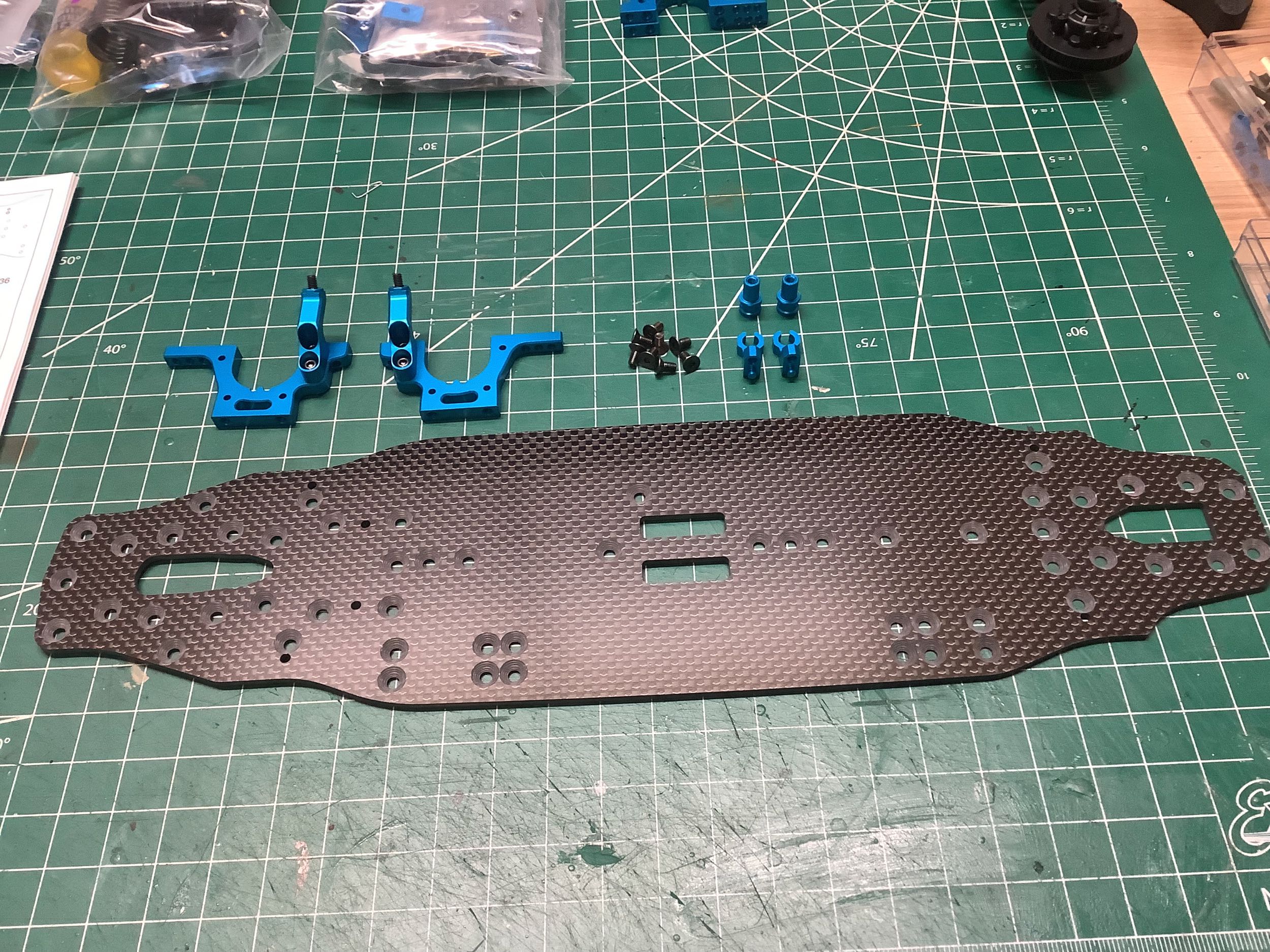
The 2.25mm thick carbon chassis is significantly narrower than
before. Sadly the manual does not offer any plan views of the
chassis so I have no easy way to make an image comparing it to the one
from the TRF 420. The TRF 421X switched to an aluminum lower deck
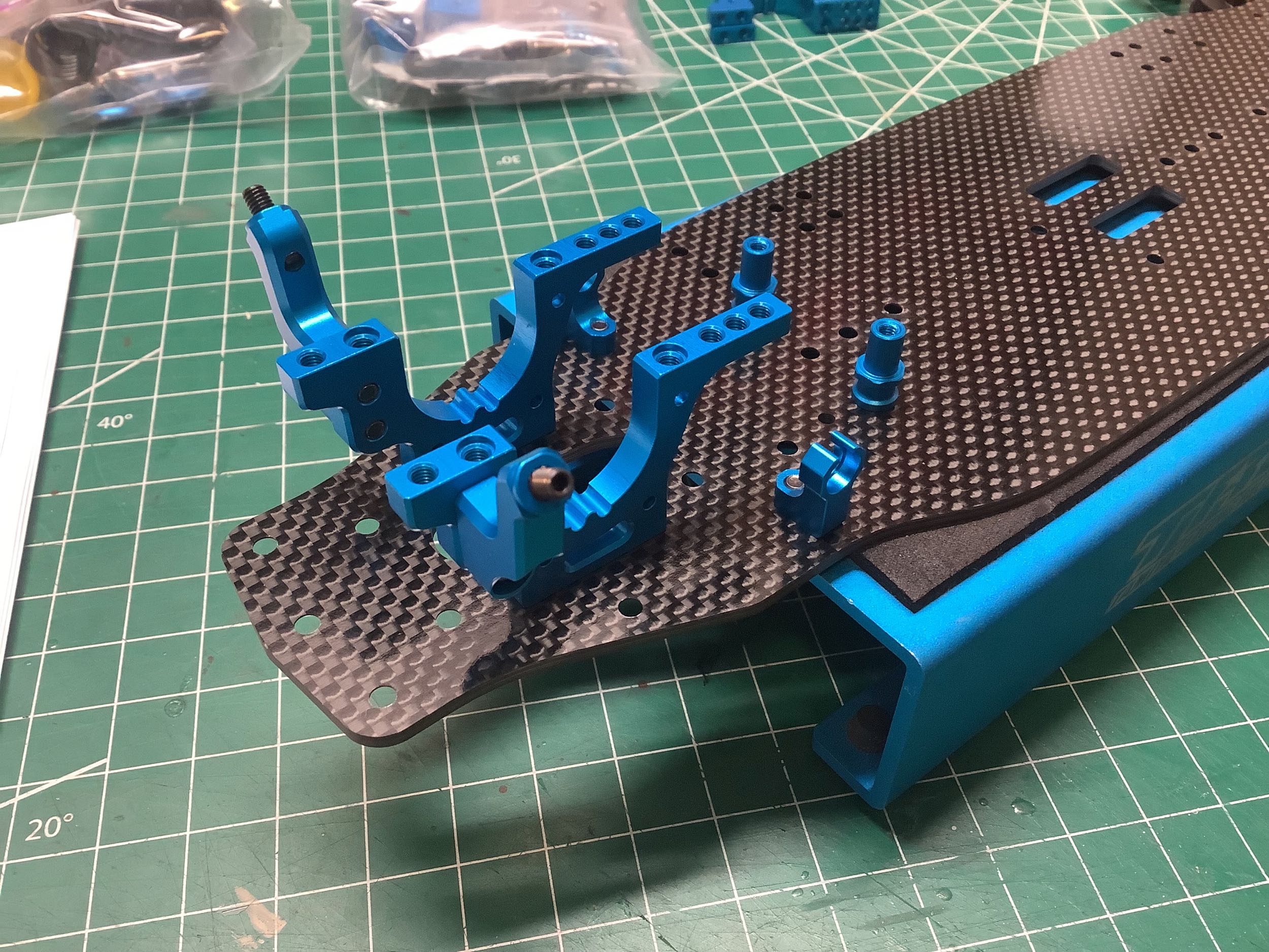
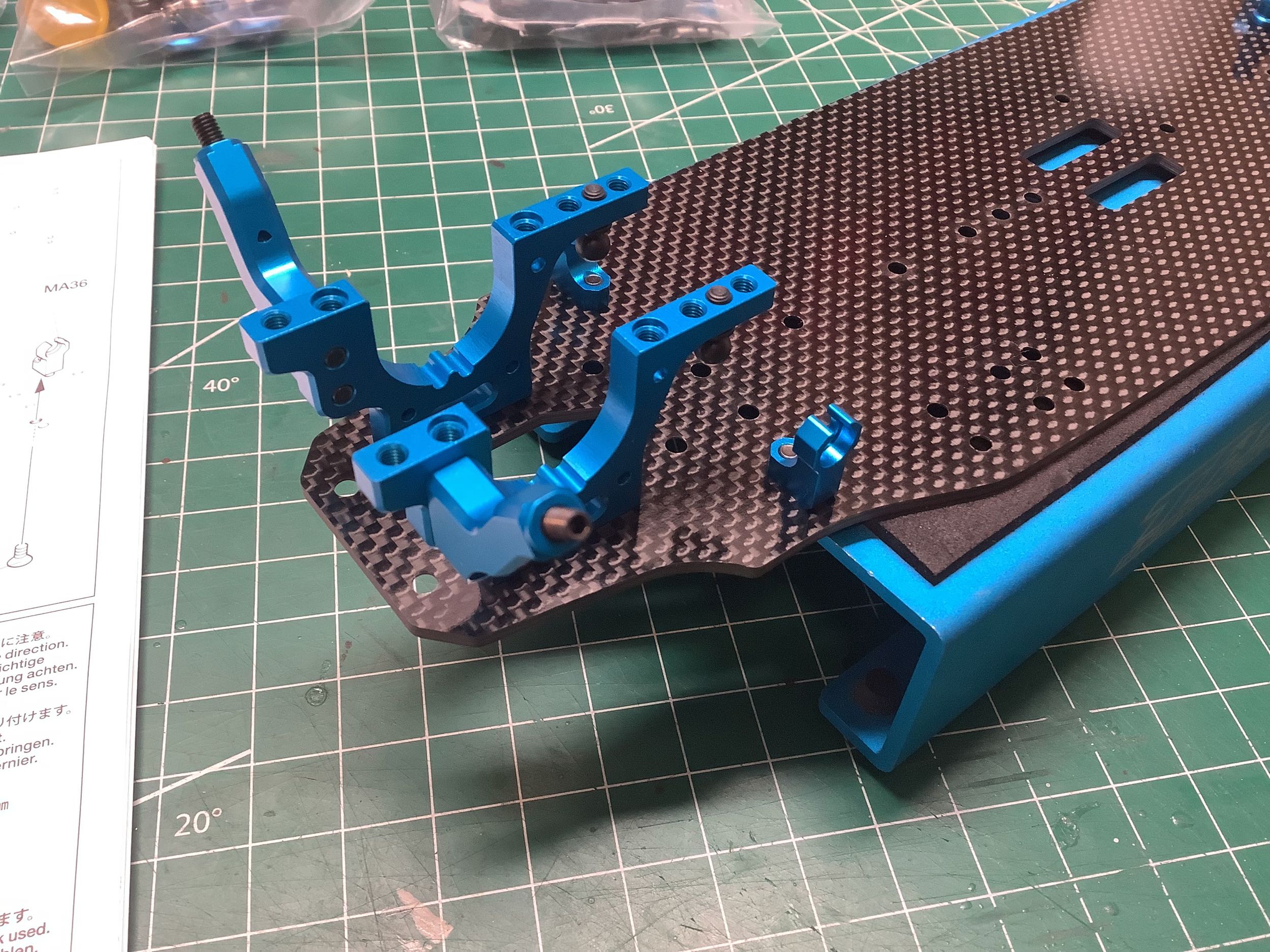
(which was optional on this model). Step 3 installs the forward
bulkheads to the chassis and also includes the steering posts and new
stabilizer mounts. The TRF 420 had introduced a new method of
pivoting the sway bars on ball bearings which was a huge improvement,
but the ball bearing mounts were integrated with the bulkheads which put
the sway bars ahead of the suspension. That won't work here
because of the way the shocks mount. Instead the stabilizer
bearing mounts are separate parts mounted behind the bulkheads to the
chassis as shown. The stabilizer mounts have guide pins to
guarantee they are aligned with the chassis (and each other). The
TRF 421X added similar guide posts to the bulkheads as well.
The rear goes together almost exactly like the front. The
non-obvious difference is in the shape of the damper stays which are
slightly longer in the rear. Step 4 assembles them to the
bulkheads and installs it all on the chassis. Those set screws you see
sticking down from the rear bulkheads will be used to attach the toe
links for the rear suspension.
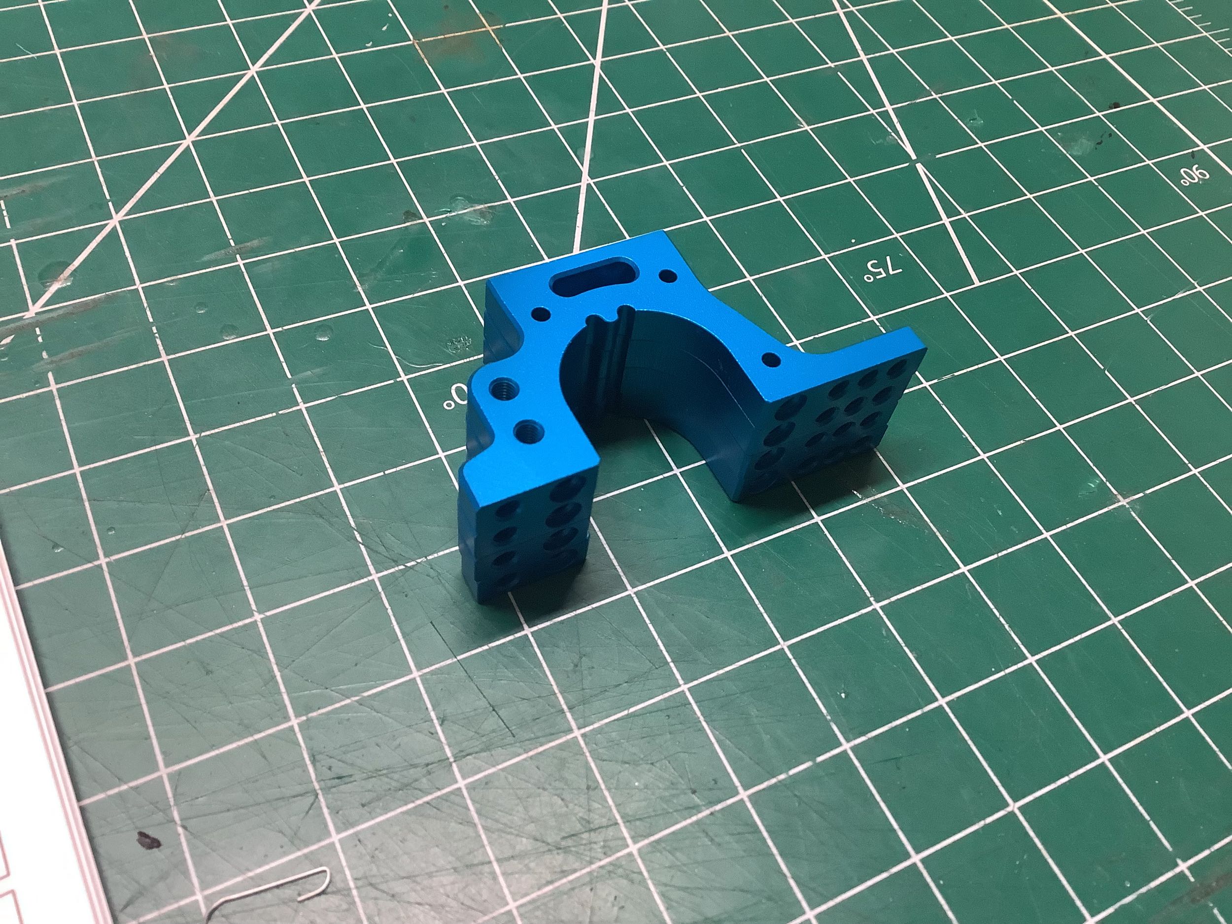
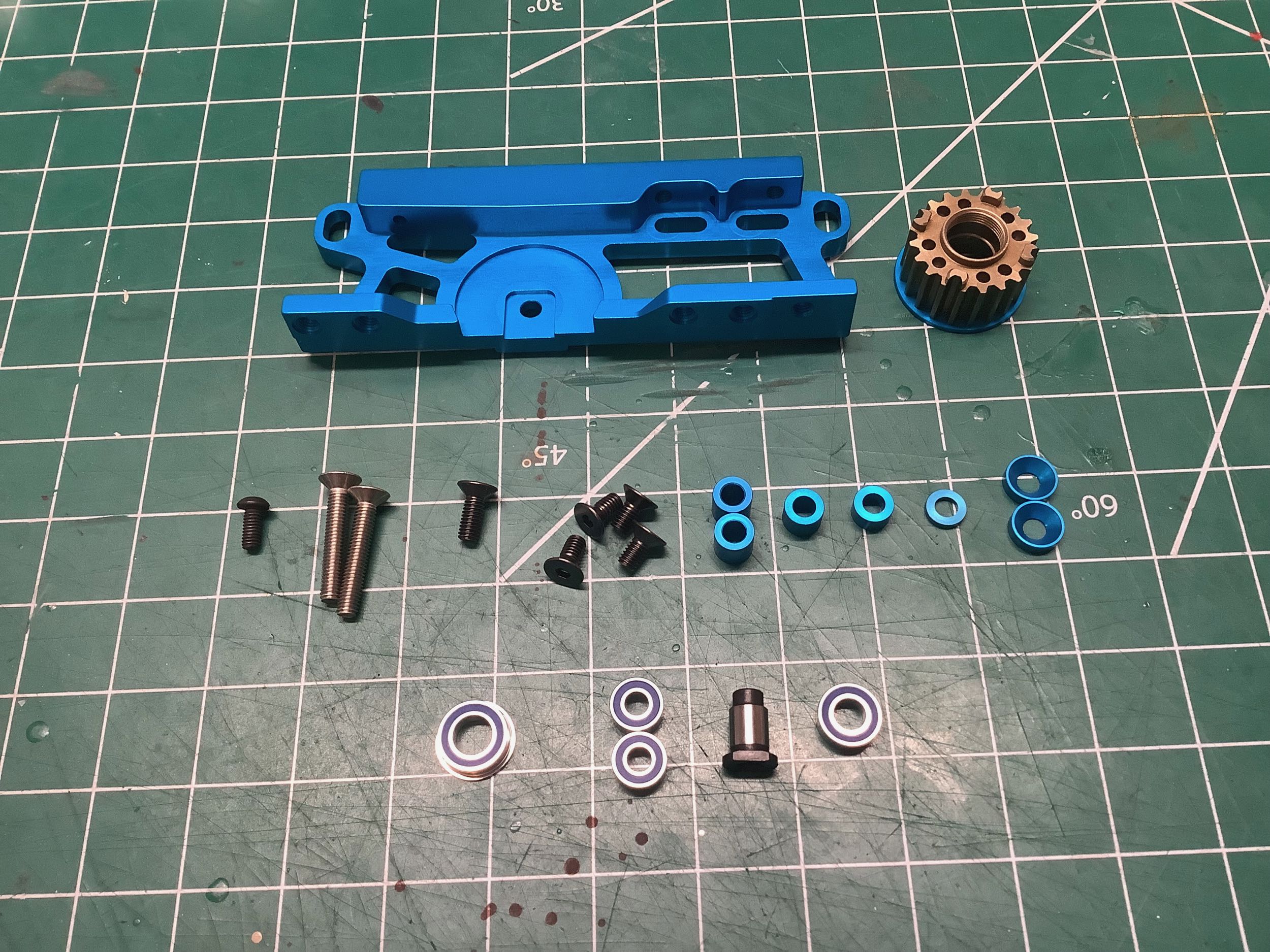
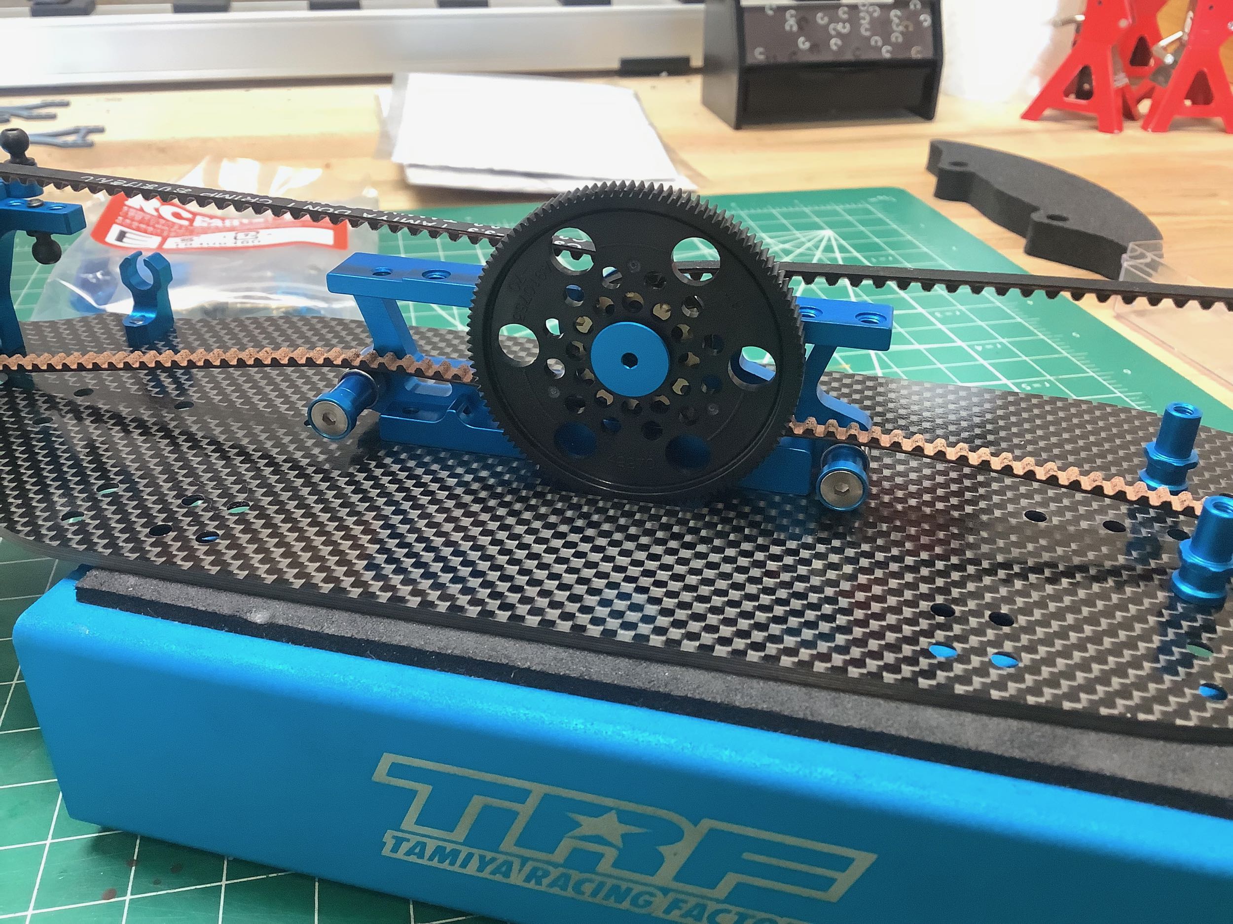
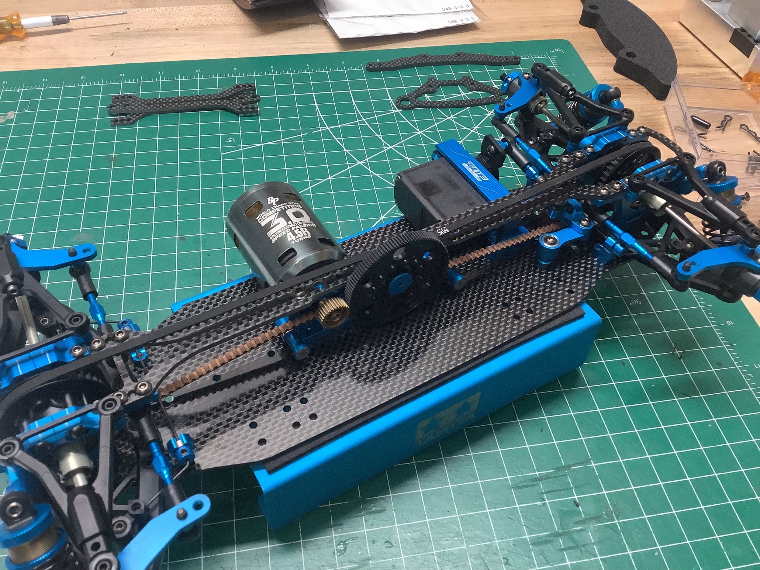
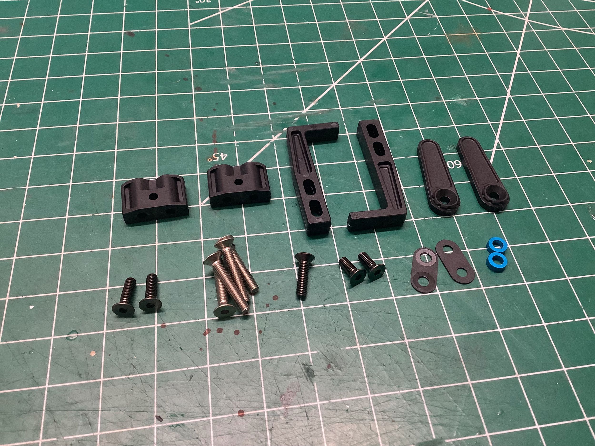
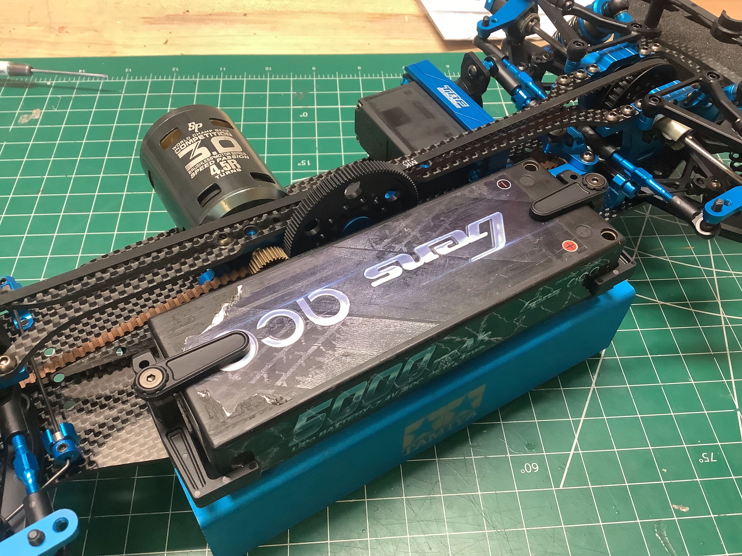
Step 5 builds the motor mount which is a very complex machined part
which will house the center pulley, the spur gear, some belt rollers,
battery stops, and support the upper deck. The front and rear
belts share the same 20T hard anodized pulley and put both belts on the
same side of the spur gear. This is a first for the TRF line, and
it means the spur gear will not be centered in the chassis and the motor
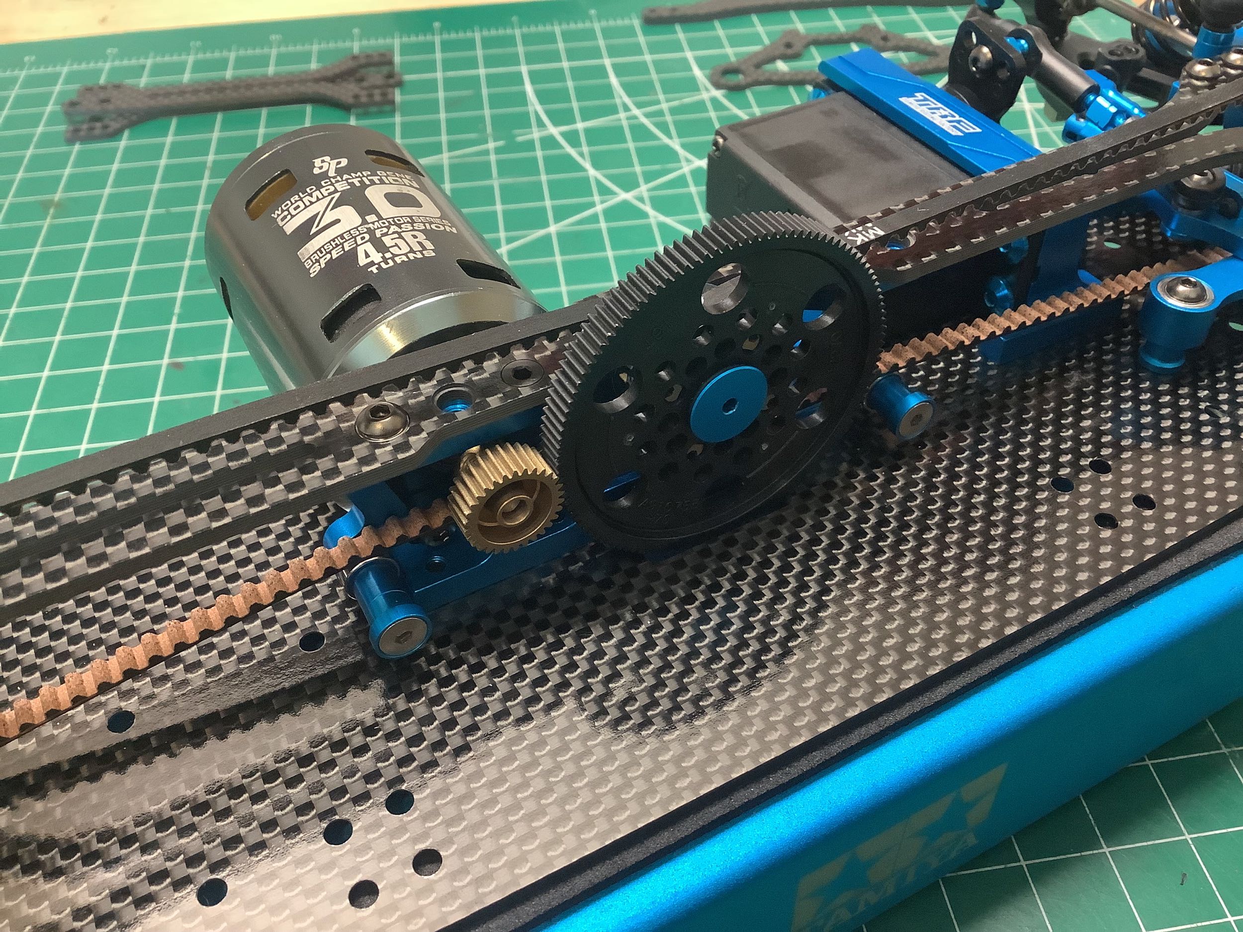
will be located a bit more outboard to match. There are ball
bearing rollers to accomplish minor belt tensioning (they can be
adjusted up and down to add more support). On the ends of the
roller posts are washers which serve as stops to keep the battery away
from the spur gear. Different parts are used for Tamiya Li-Fe
batteries versus the ones everyone else in the world uses. The
screws which support the rollers and battery stops appear to be
titanium. Most of the screws in the model are steel, and it is not
obvious why these are different. The TRF 421X used a slightly
different motor mount which lowered the motor by 1.04mm and required a
relief cut in the chassis.
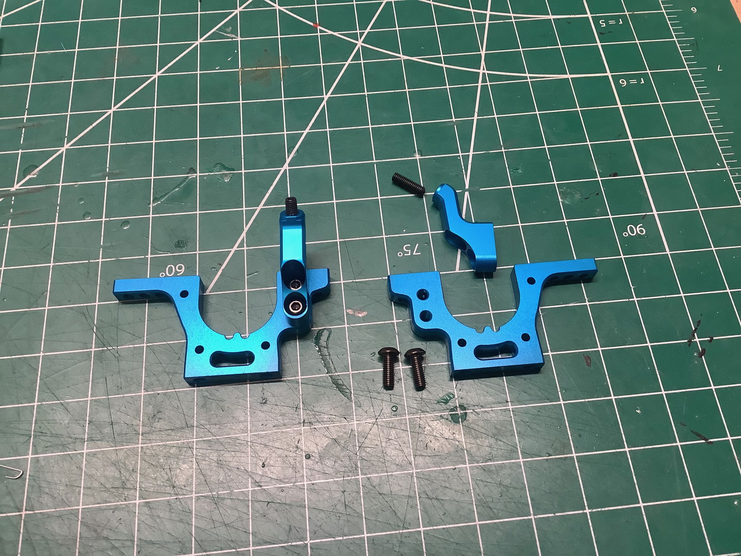
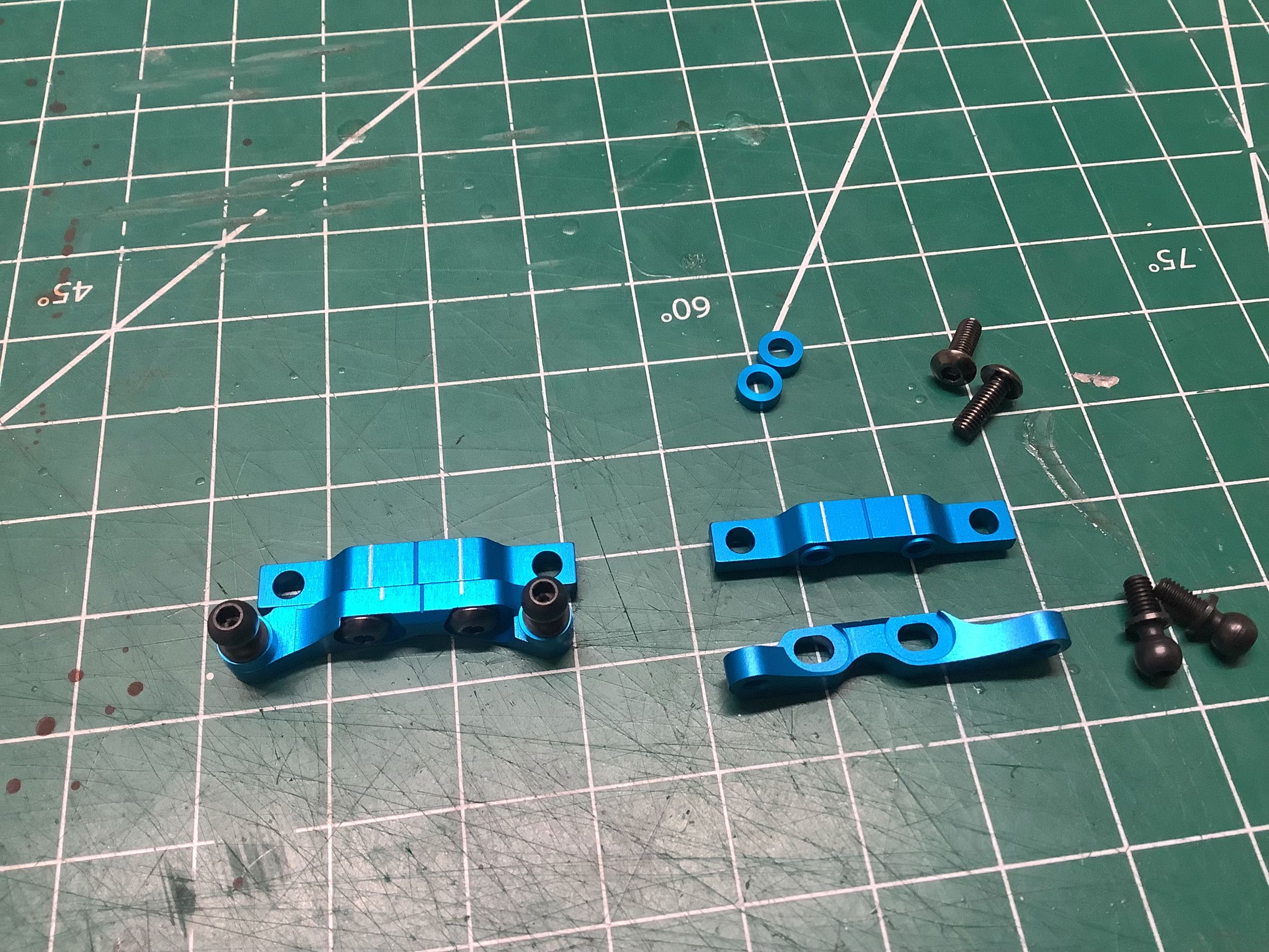
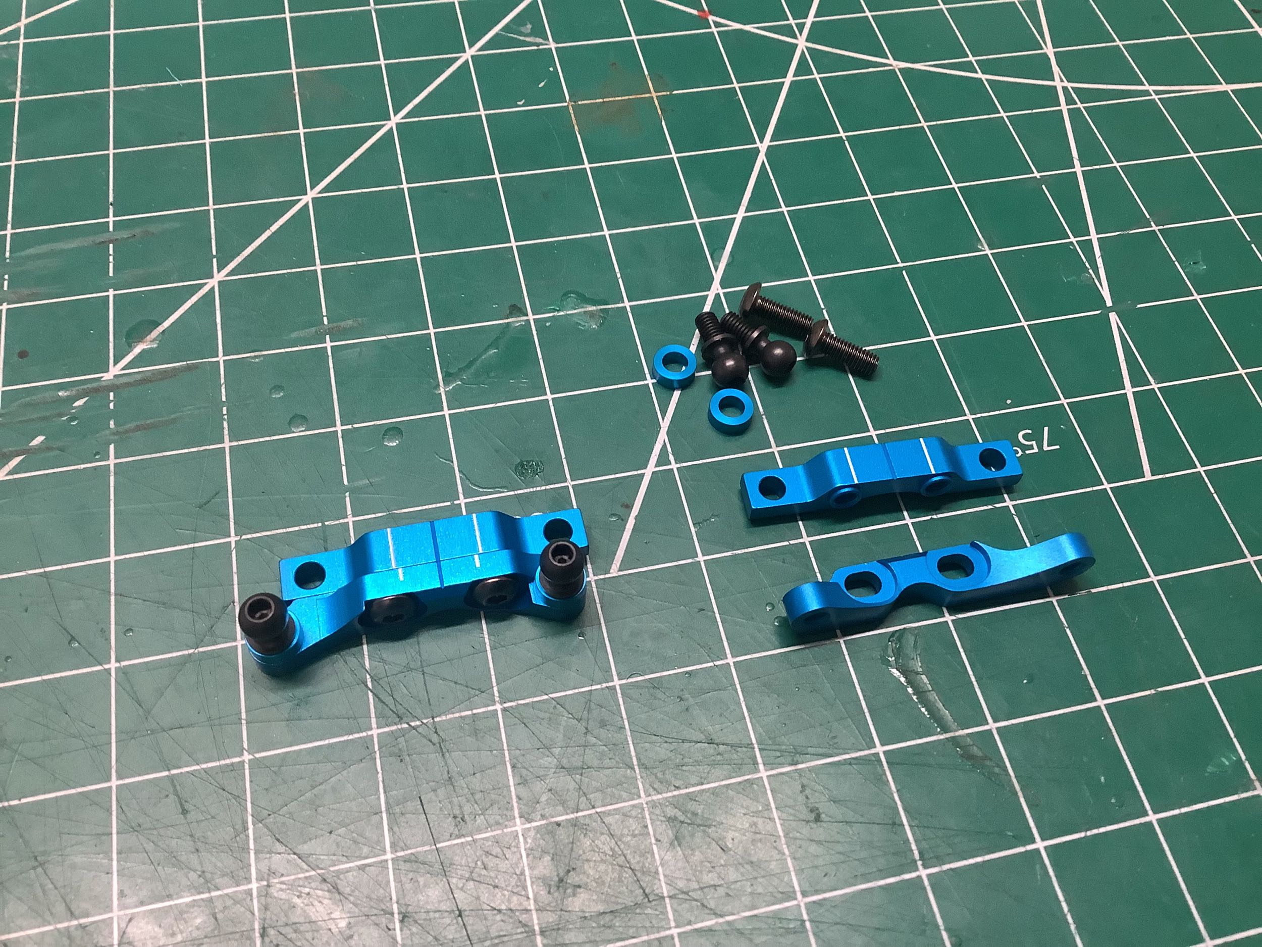
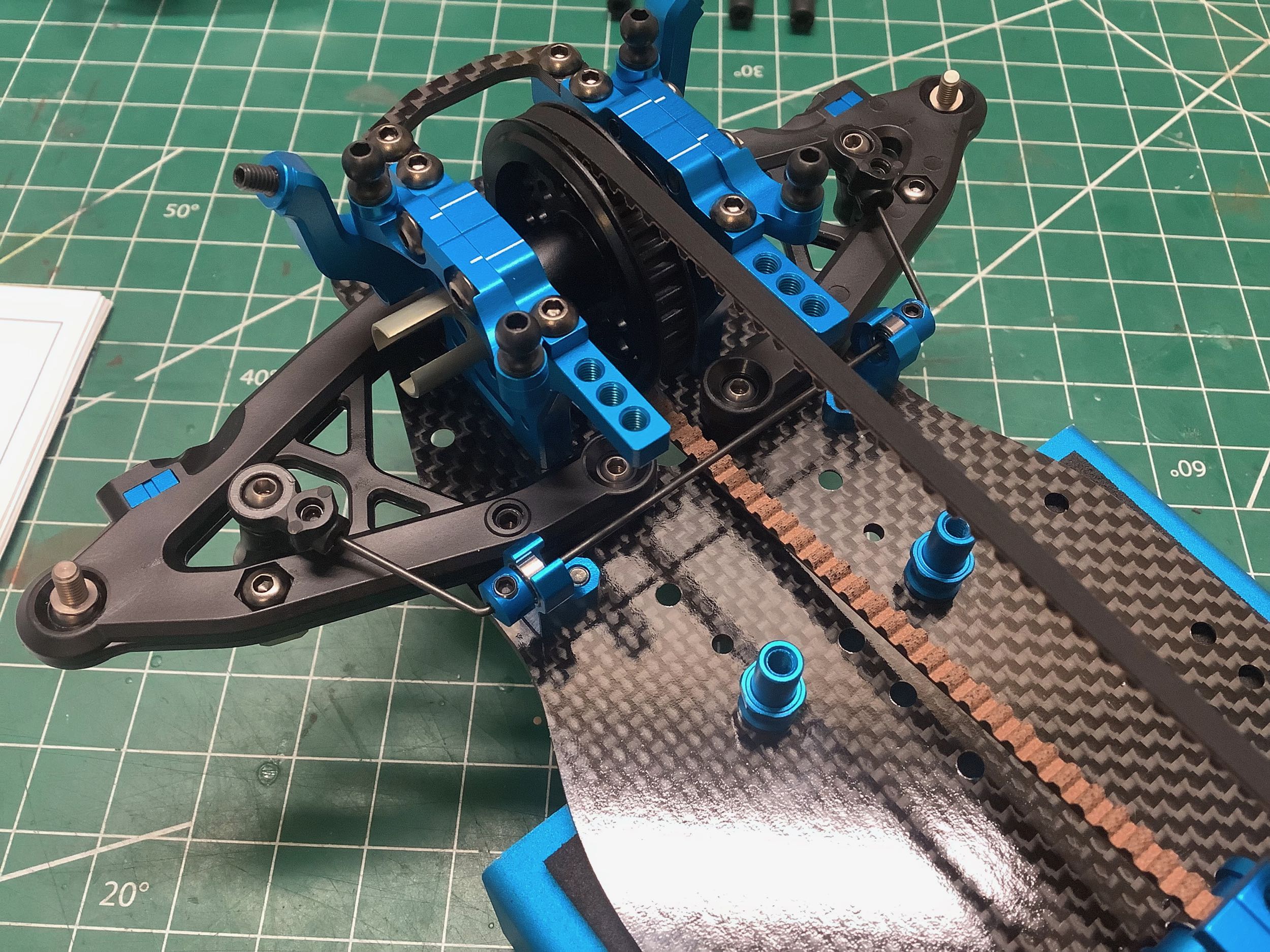
Step 6 builds the rear upper bulkheads (left) which include the upper
suspension arm mounts. The parts shown at the top of the pictures
are the upper bulkheads which will lock the differential into place once
installed. The parts have two white lines etched into them
centered above two slotted holes. The parts shown at the bottom of
the pictures are the upper suspension arm mounts. They have two
5mm ball joints on them to support the new wishbone shaped upper
arms. When attaching these parts, they can be slid in the slots on
the bulkheads to either align with the white lines or move slightly
forward of or behind them. This will move the longitudinal
position of the upper arms with respect to the lower and result in a
caster angle (the upper and lower kingpins will not be vertically
aligned). On the rear, the options are 0.5°, 1.5°, or 2° (you
don't want much caster on the rear). The default setting is the
minimum 0.5°. The right hand picture shows the front assembly from
Step 10. They are the same parts used on the rear, but because of
the position they are installed on the chassis you end up with 3°, 4°,
or 5° of caster. The nominal 4° is used by default. Changing
the height of the spacers under the ball joints affects how the toe
angle changes as the suspension is compressed. The default setup
uses 2mm spacers. The TRF 421X moved the upper arm support 1mm
further inboard with modified suspension arm mounts.
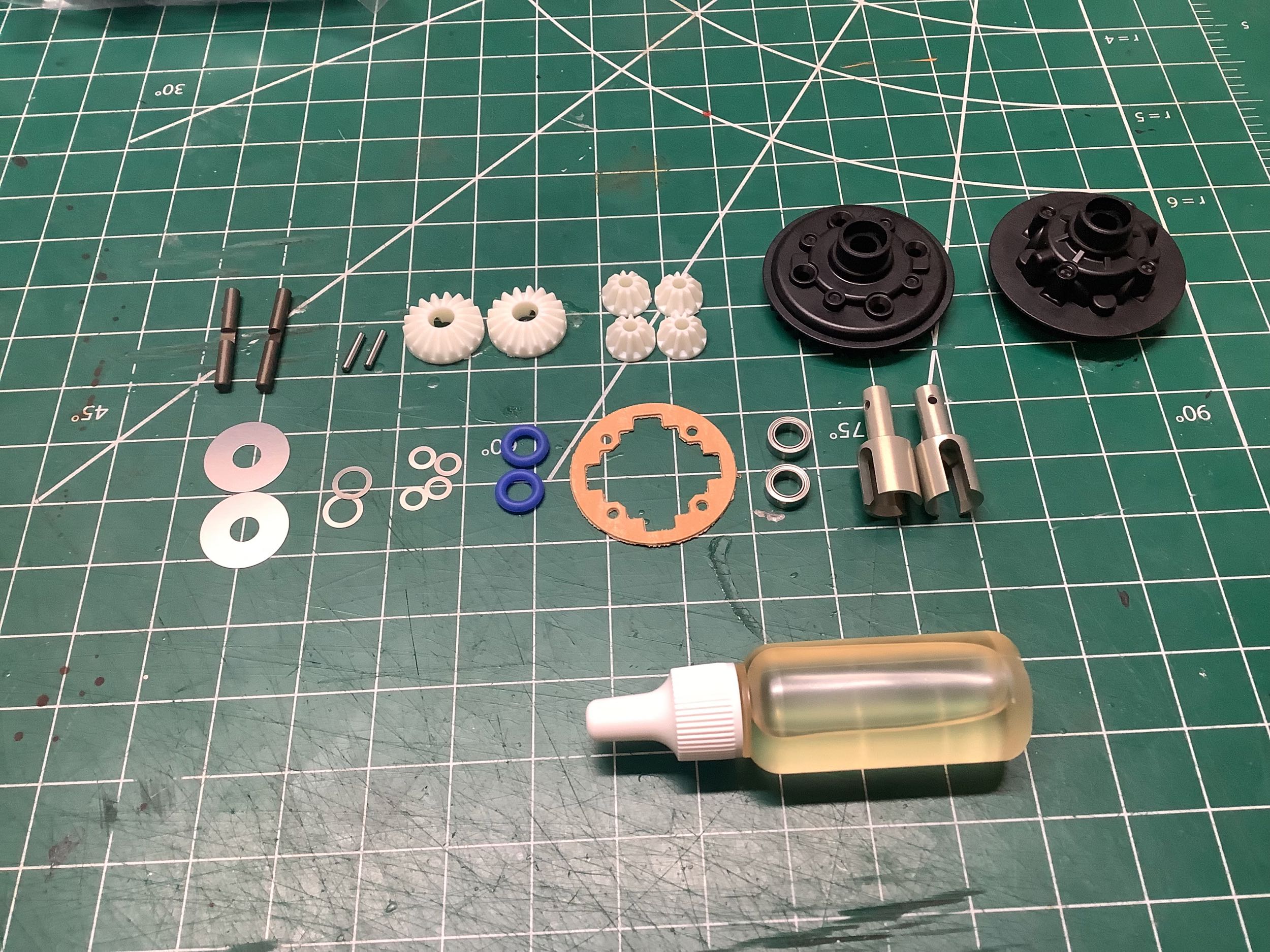
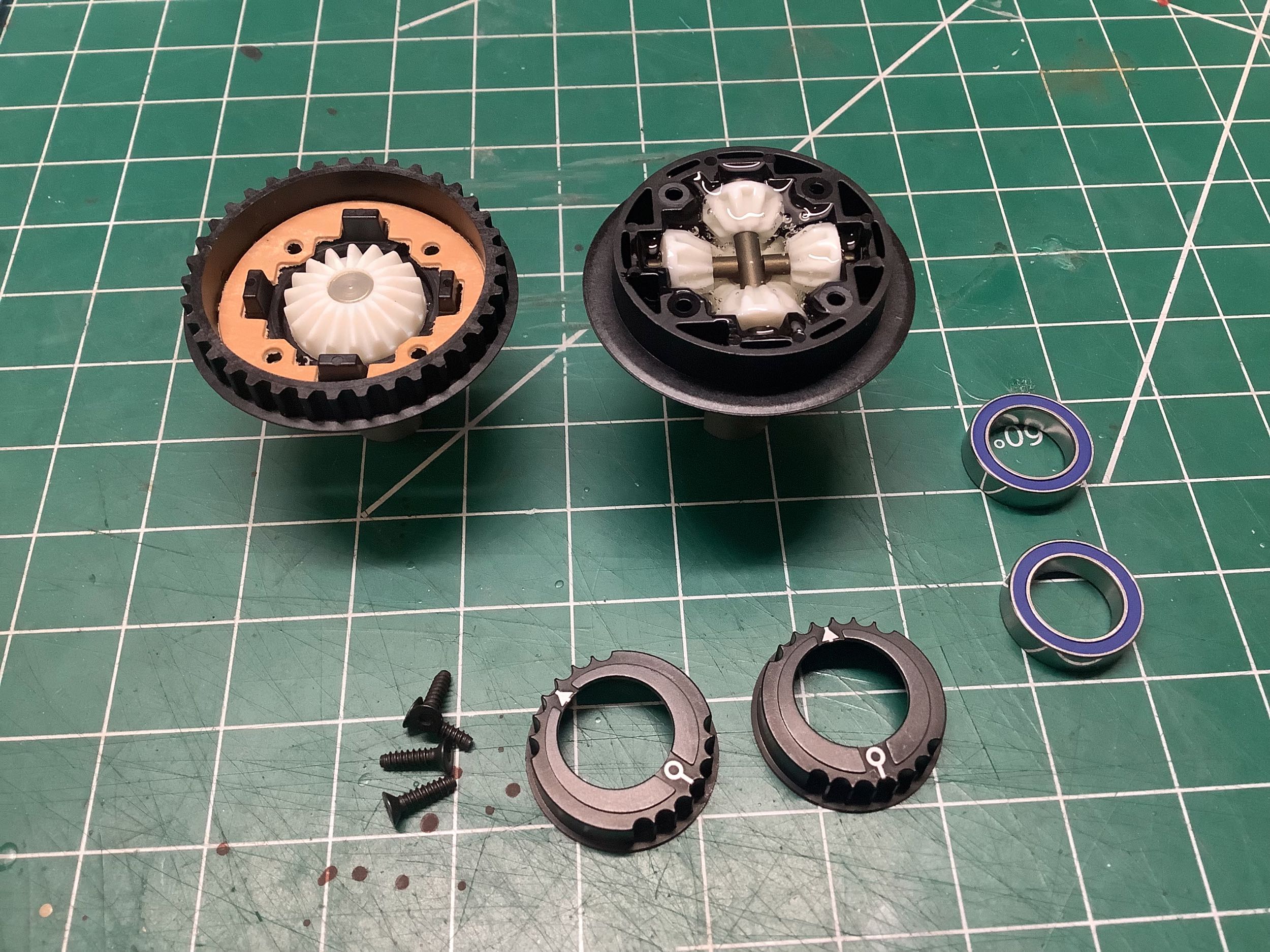
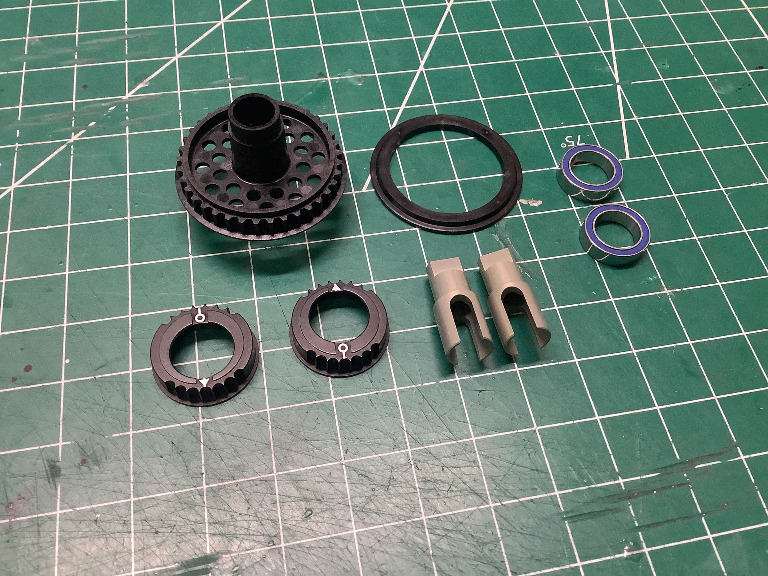
The rear sealed gear differential is built in Step 7. While it
appears to be the same as the one from the TRF 420 (and the TRF 419
before that), it has been changed slightly. The 37T pulley has
been moved closer the center of the chassis (less offset). This
means that the deep side of the differential housing has gotten slightly
shallower while the pulley side has gotten slightly deeper. The
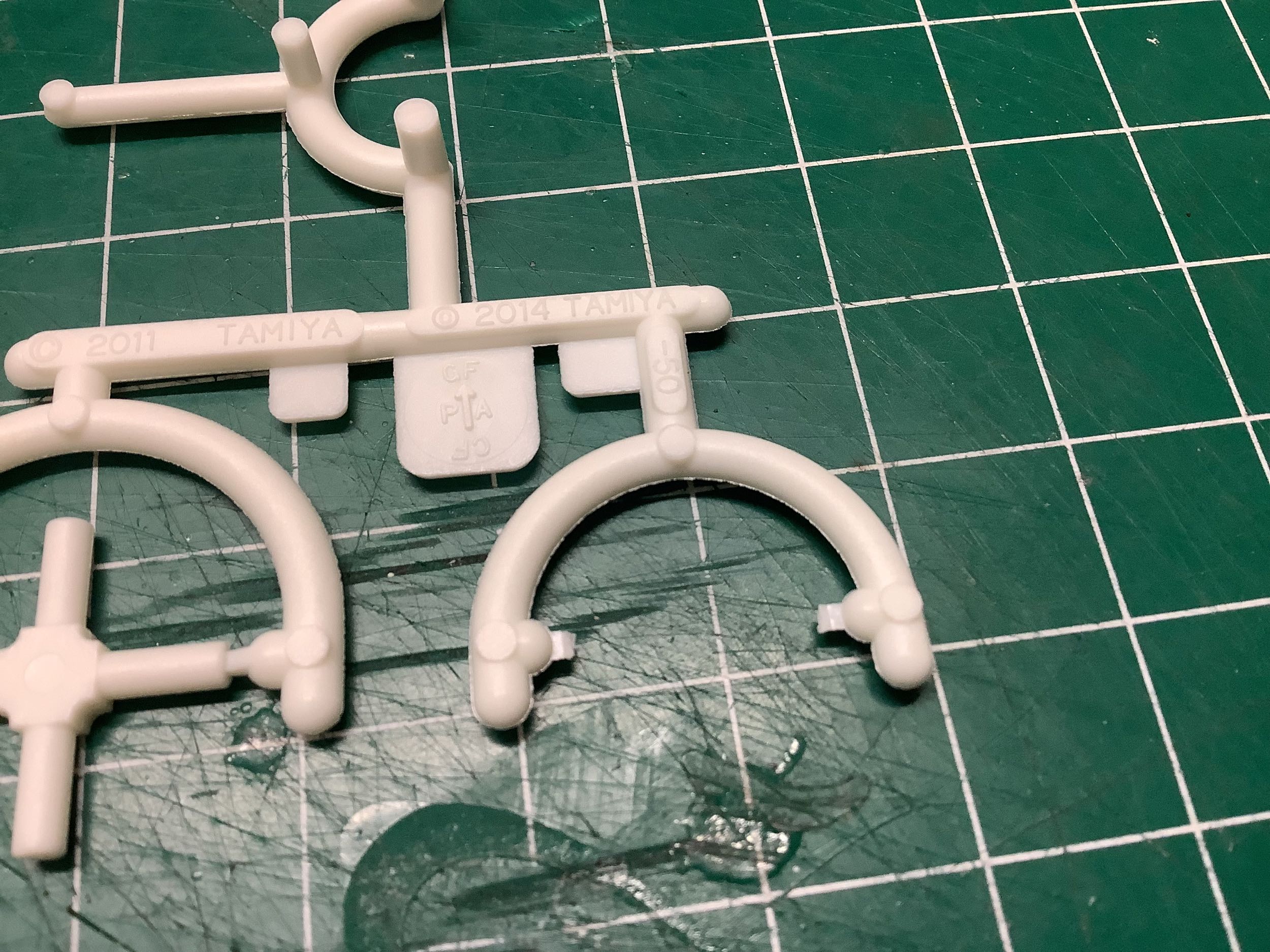
picture on the right shows that the white gears which I had previously
assumed were Delrin are actually glass filled Nylon. So why does
the sprue have both 2011 and 2014 stamped on it? The original GV
parts tree came from the TA-06 in 2011. In 2014 it was modified
for the TRF 419 to include larger diameter gears but retained the cross
for supporting the spider gears on cheaper models (the TRF line uses
metal supports). The color was changed from black to white to
distinguish them since the gears cannot be mixed.
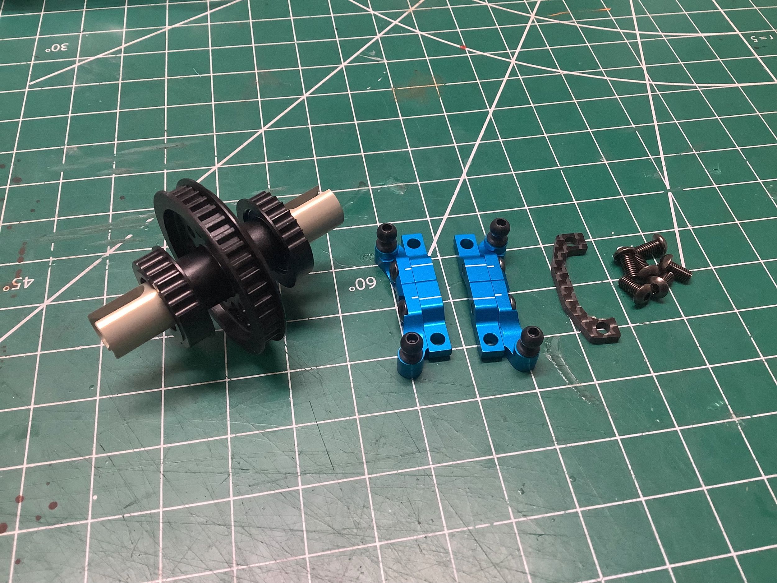
Step 8 fills the differential with 3000 weight oil and installs the
bearings and bearing holders. For the first time, the eccentric
bearing holders are machined aluminum instead of plastic. Note
that bearings are blue rubber shielded instead of fluorine shielded like
the TRF 419 and older. This might appear like a downgrade, but
apparently the newer rubber shields have been improved by Tamiya in some
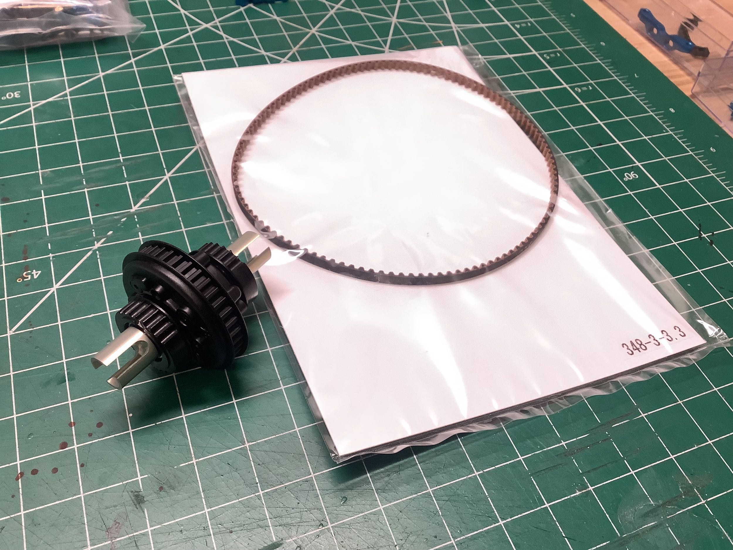
way. The belt is shown on the right. This model uses two
identical belts for front and rear which is new for the TRF 421.
Ever wonder what that code on the belt actually means? 348 is the
length in millimeters. The second number is the pitch, one tooth
per 3mm of length for a total of 116 teeth. The third number is
the width, 3.3mm.
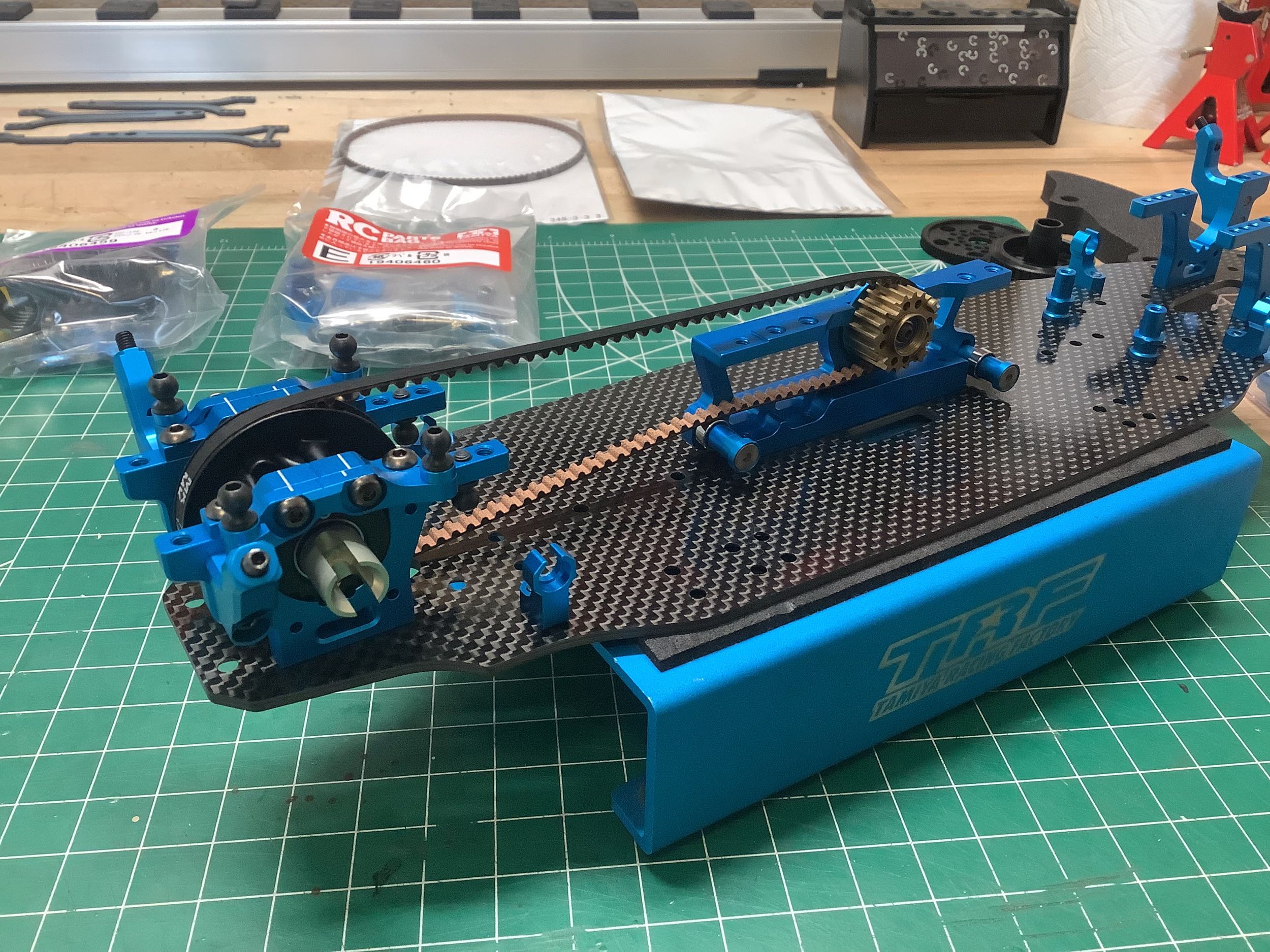
Step 9 installs the rear differential, upper bulkheads, and belt on the
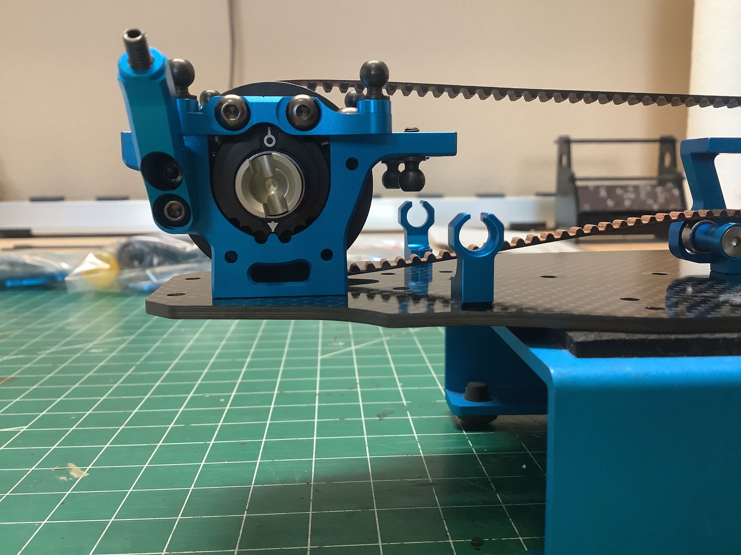
chassis. The picture on the right is taken directly from the side
showing the eccentric bearing holders. These bearing holders have a
0.8mm offset (the bearing is 0.8mm off
center). Since they are centered by default, this means that up to
0.8mm of belt tension can be added or removed by rotating them. It
also
means that flipping them upside down will change the height of the
differential by
1.6mm. Optional 0.5mm offset bearing holders are available.
The front uses a direct coupling rather than a differential which has
been standard since the TRF 417. Step 11 assembles it. The
drive cups appear to be aluminum which reduces the rotating mass of the
assembly. The plastic pulley flange snaps into place on the 37T
pulley and does not need to be glued like some older models.
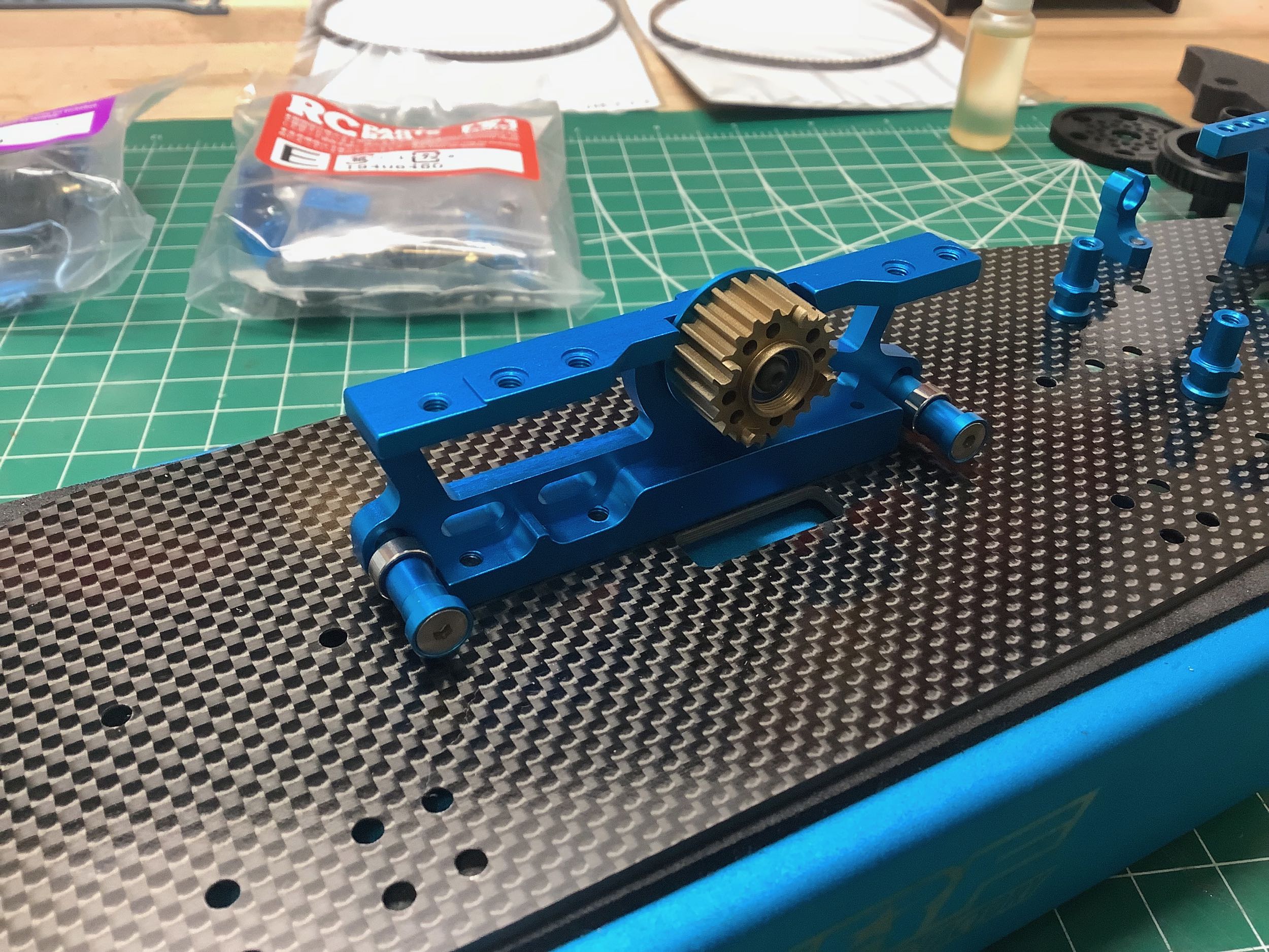
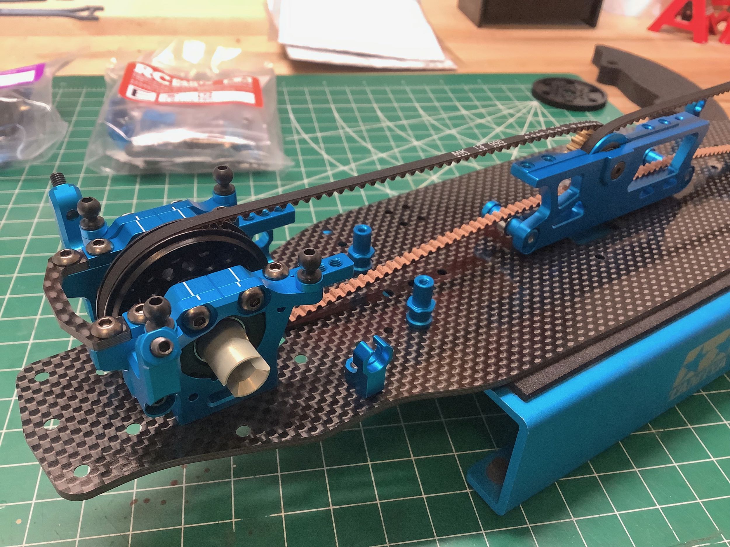
Step 12 attaches the front pulley assembly to the chassis along with a
little U-shaped front stiffener to tie the left and right bulkhead
together and keep them properly spaced. The rear will be connected by a carbon body mount later.
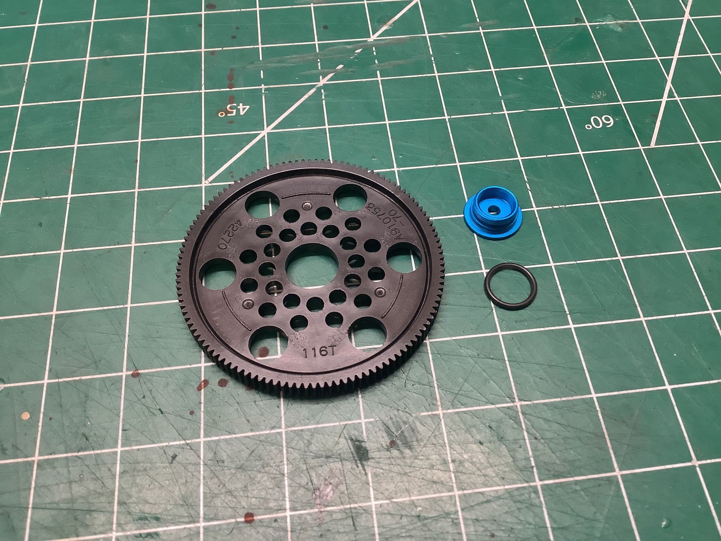
Step 14 installs the 116T, 0.4 mod spur gear. It presses onto the
center pulley which uses 4 tabs to grab meting holes on the spur
gear. There is a slight interference to keep this fit tight.
Instead of using a screw to retain the spur gear, this model uses an
aluminum gear nut which threads directly into the center pulley.
It uses an o-ring to provide a tight fit and prevent loosening.
But wait, what happened to Step 13? I totally missed that
one. It installs part K3, a spacer that fits behind the spur gear
to retain the belts. I got back to it later. Everything up
to now has only got us through hardware Bag A!
Now that the belts are installed, we can open hardware Bag B and start
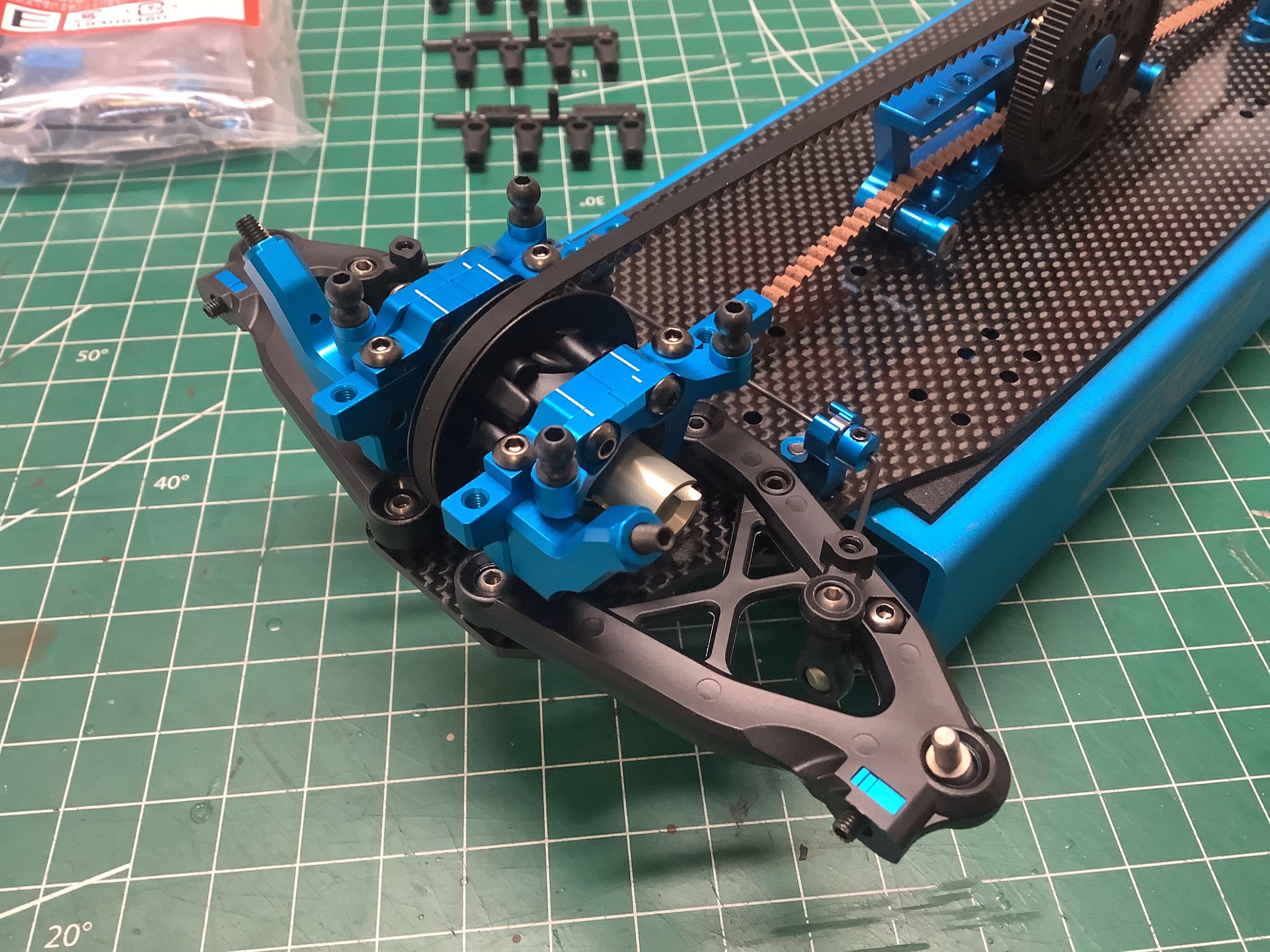
on the suspension with Step 15. The lower arms are very obviously
new for this model and feature a wishbone shape and connect to the
chassis with ball joints. This is a great departure from prior
models which used narrower arms pivoting on hinge pins and supported by
suspension blocks. Those suspension blocks could use different
inserts to alter the arm height, roll center, skid angle, track width,
and sweep angle. All of that has been replaced with these simple
ball joins. Roll center and skid angle can still be adjusted by
placing spacers under the ball joints, but track width and sweep angle
are fixed. The ball joints are located closed to the center of the
chassis than the hinge pins used to be which means the suspension arms
need to be longer to compensate. The long distance between the
balls requires wider arms which provides more stability. Those
little blue inserts provide the location for the set screw which will
support the bottom end of the dampers. Different inserts (not
included) can be used to move the lower support inboard or
outboard. There are also aluminum balls which bolt to the arms to
connect to the sway bars later. The kingpins are 5.8mm balls which
snap into the arms. Step 16 installs the front arms onto the
chassis.
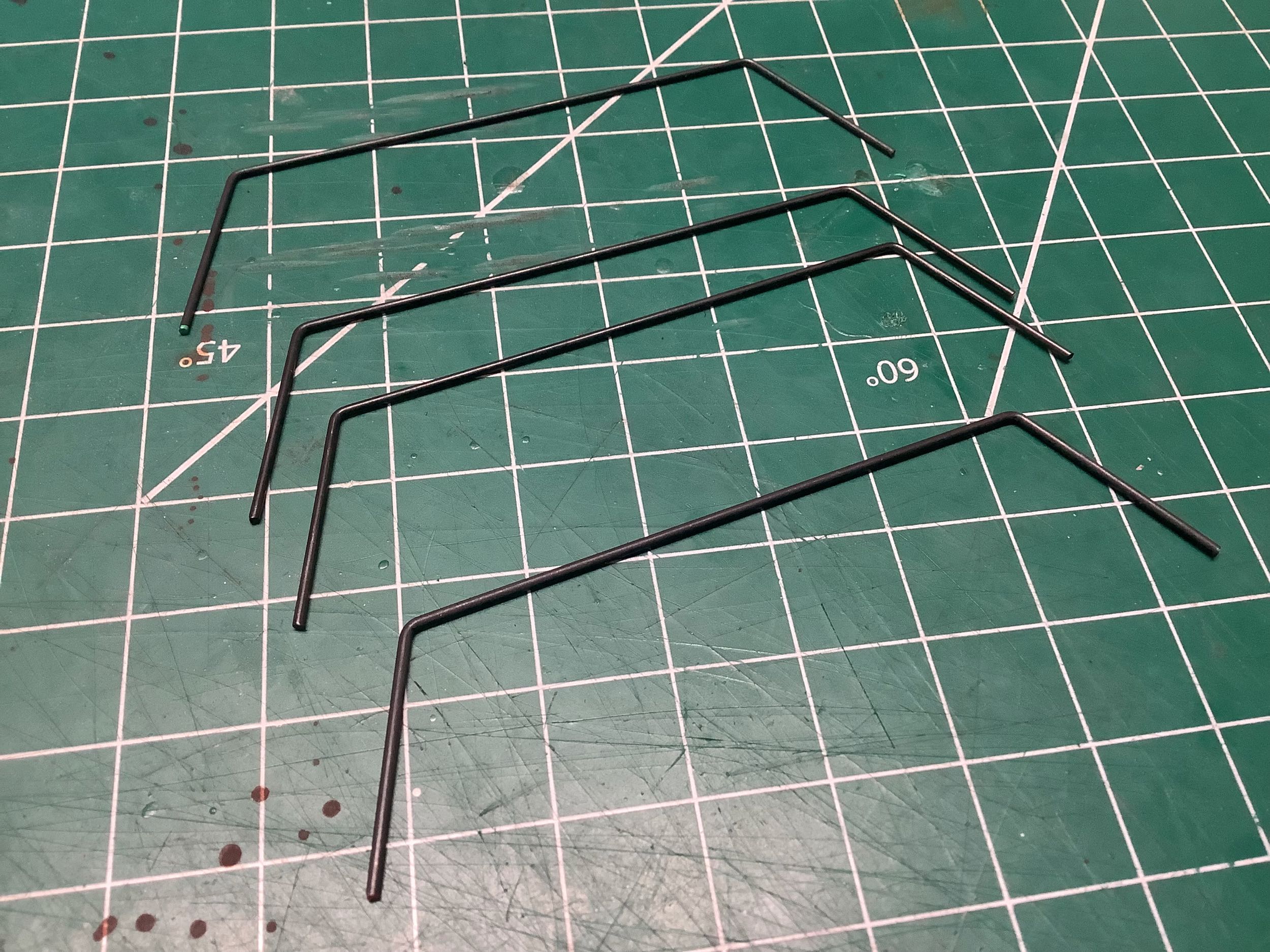
There are 4 sway bars included in the kit: one 1.0mm super soft, two
1.1mm soft, and one 1.2mm medium stiffness option. The default
settings use the soft on both front and rear. Step 17 builds the
front sway bars by installing the rod ends, stoppers, and bearings, and
then Step 18 installs them onto the chassis as shown on the right.
This works extremely well and effortlessly transfers motion from one
side to the other. This is good because many previous models didn't do
this well at all.
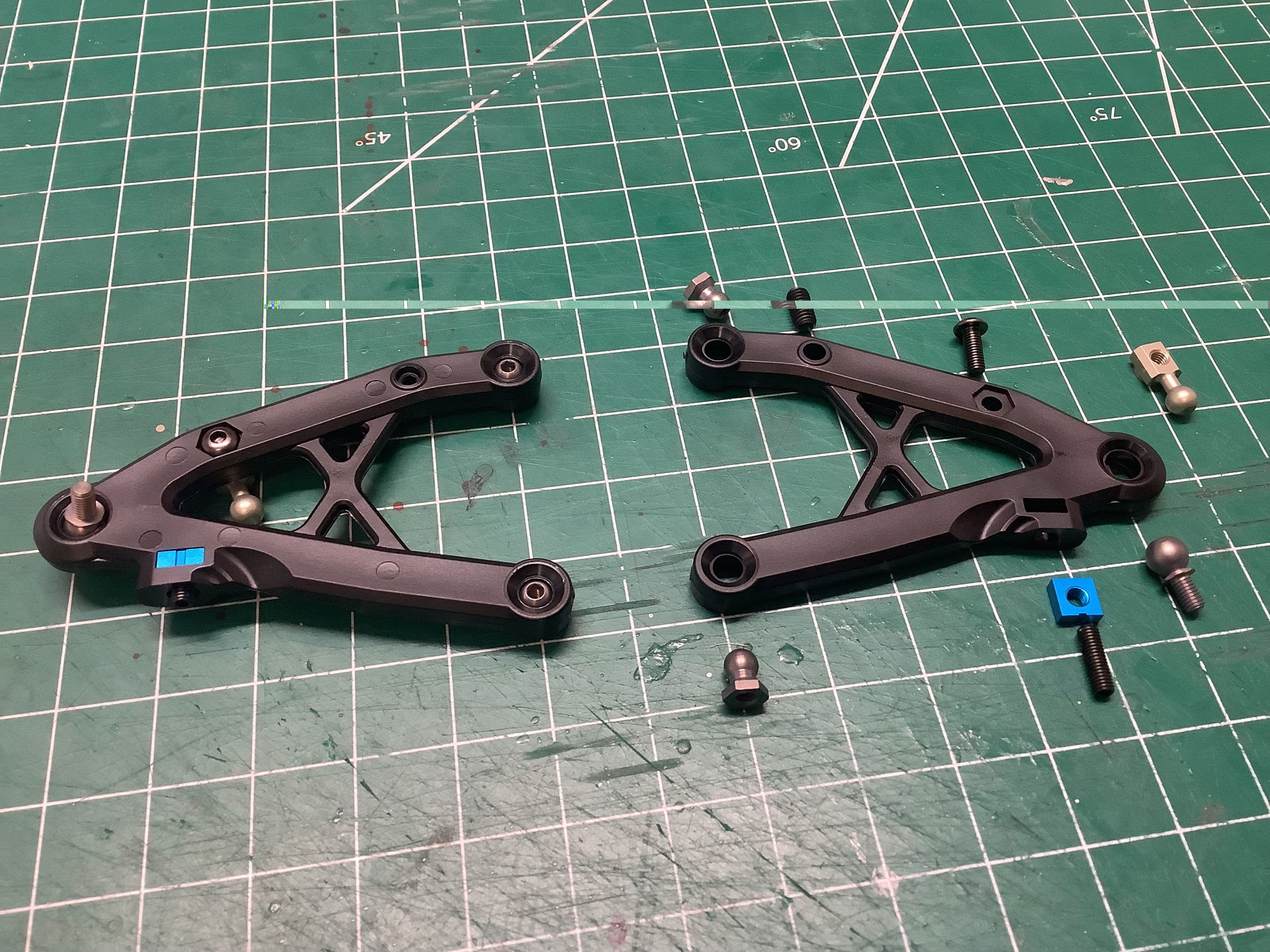
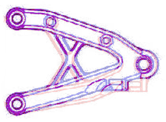
Steps 19, 20, 21, and 22 do exactly the same thing for the rear
suspension. The rear arms are not identical to the front.
The shock supports are located further outboard and the bushings are not
centered in the slots but biased toward the inboard end. The
picture on the right compares them directly. The front arms are
shown in blue, and the rear arms in red. You can see that the
overall width at the balls is the same, but the rear arms are slightly
shorter and are wider in the middle. Why? No obvious reason.
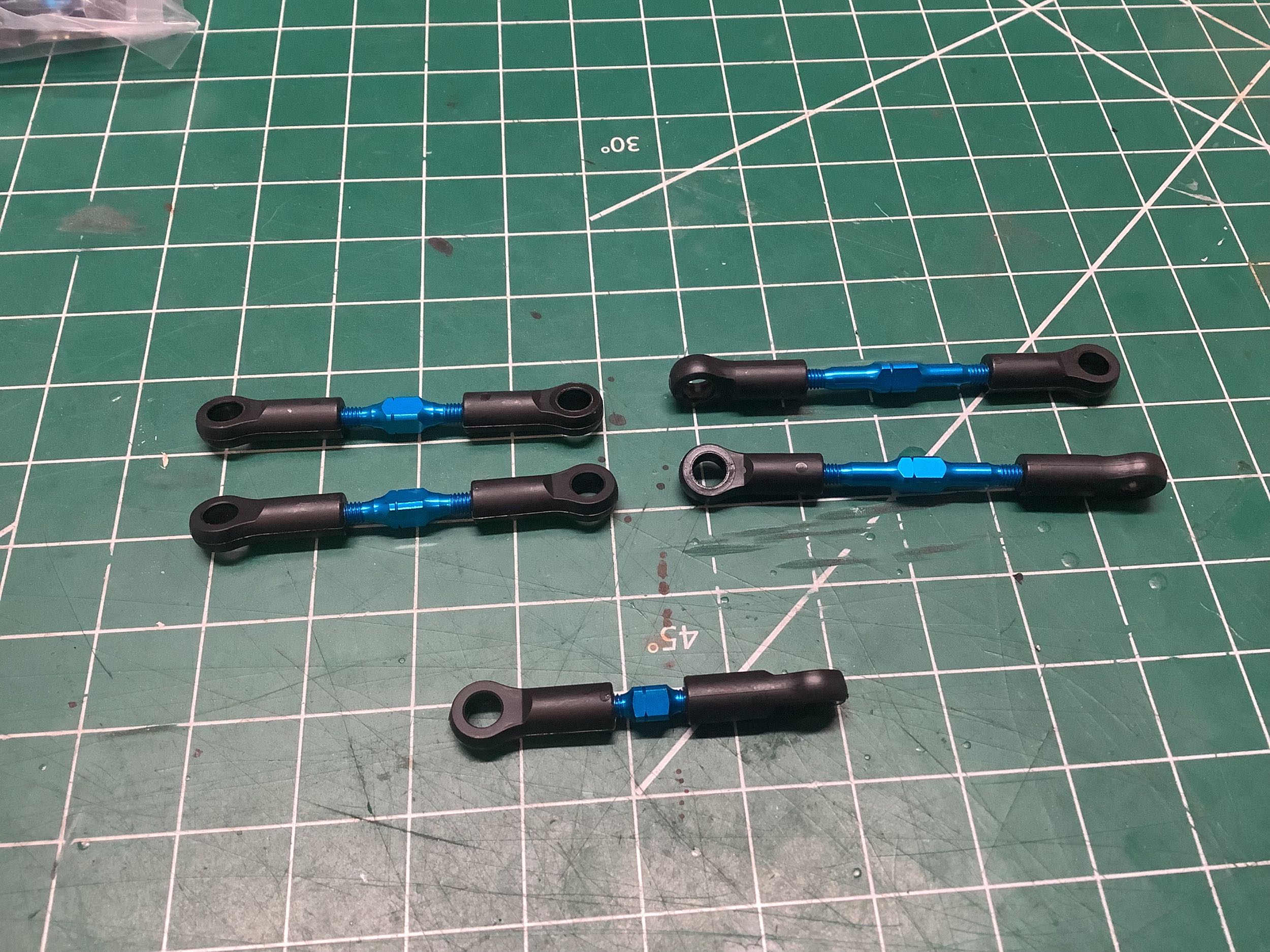
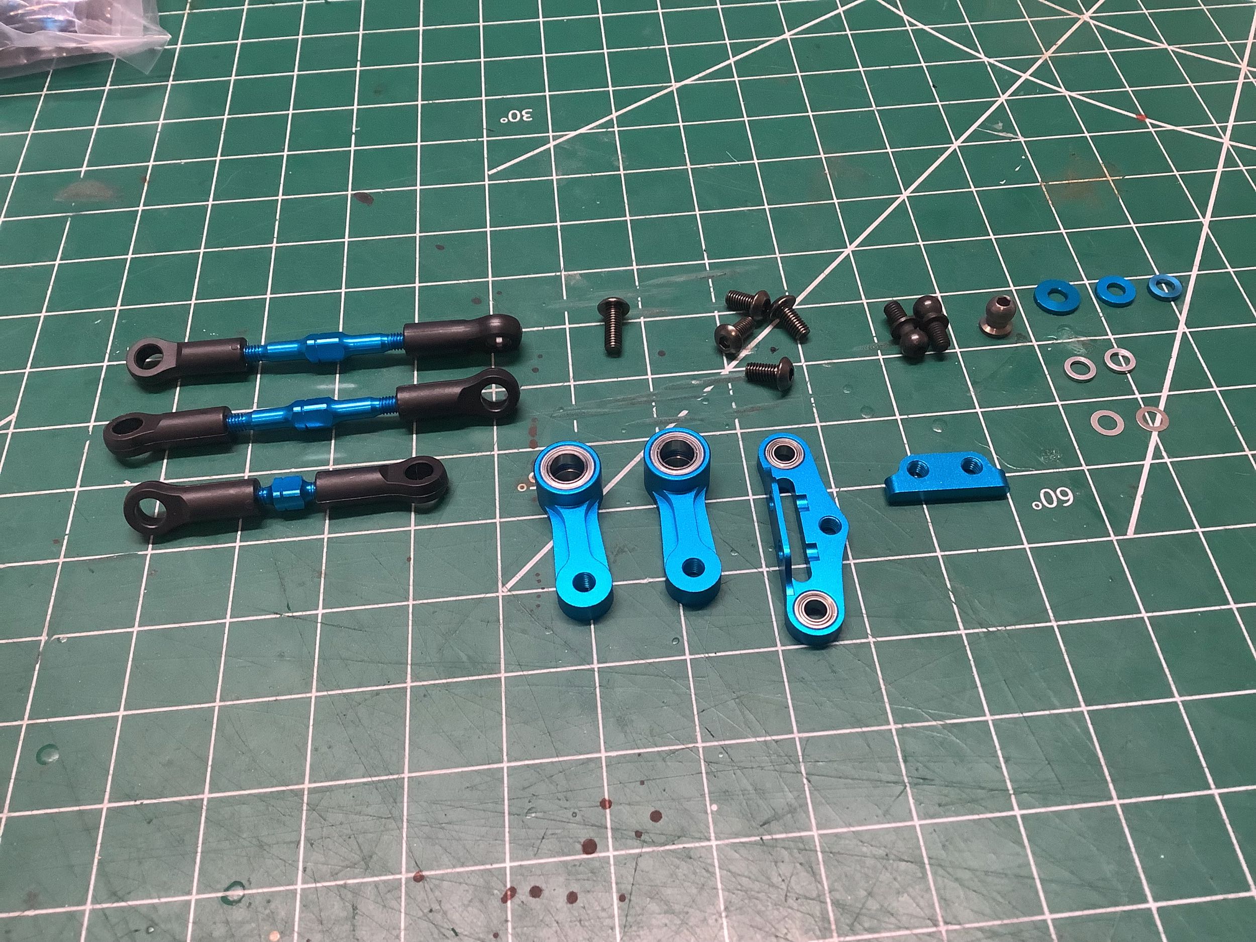
There are far fewer tie rods to make in this model compared to previous
(there are no camber links). There are two used for steering
links, one to connect to the servo, and two used to control toe on the
rear hubs. Steps 23 and 24 make all 5 links. These are
turnbuckles with one reverse threaded end. I've built them
intentionally short and then I'll adjust them to length once installed.
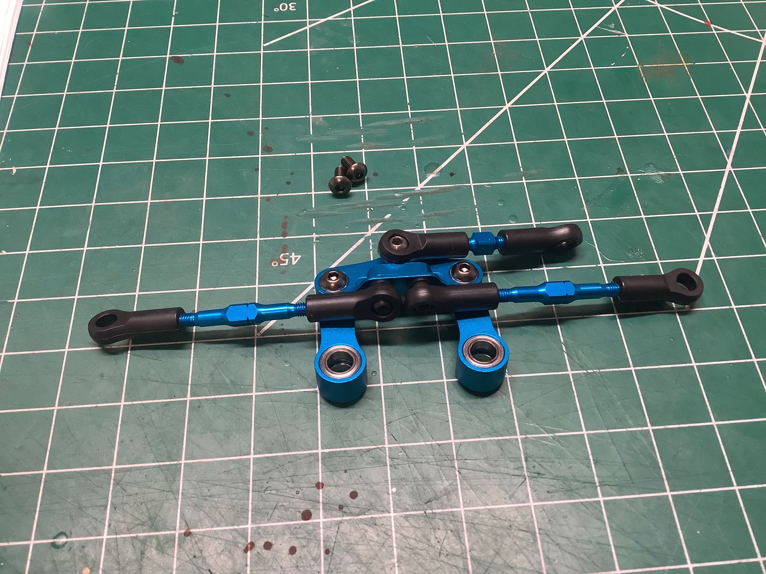
Step 25 builds the double bell crank steering system. This should
look very familiar by now as they are from the same system used on the
TRF 420 but with different options selected. The little insert is
called the steering pivot and has 8mm between the holes. Other
distances are possible. Likewise the steering bridge is available
with different offsets. The assembly is shown on the right (which
is subtly wrong as explained below).
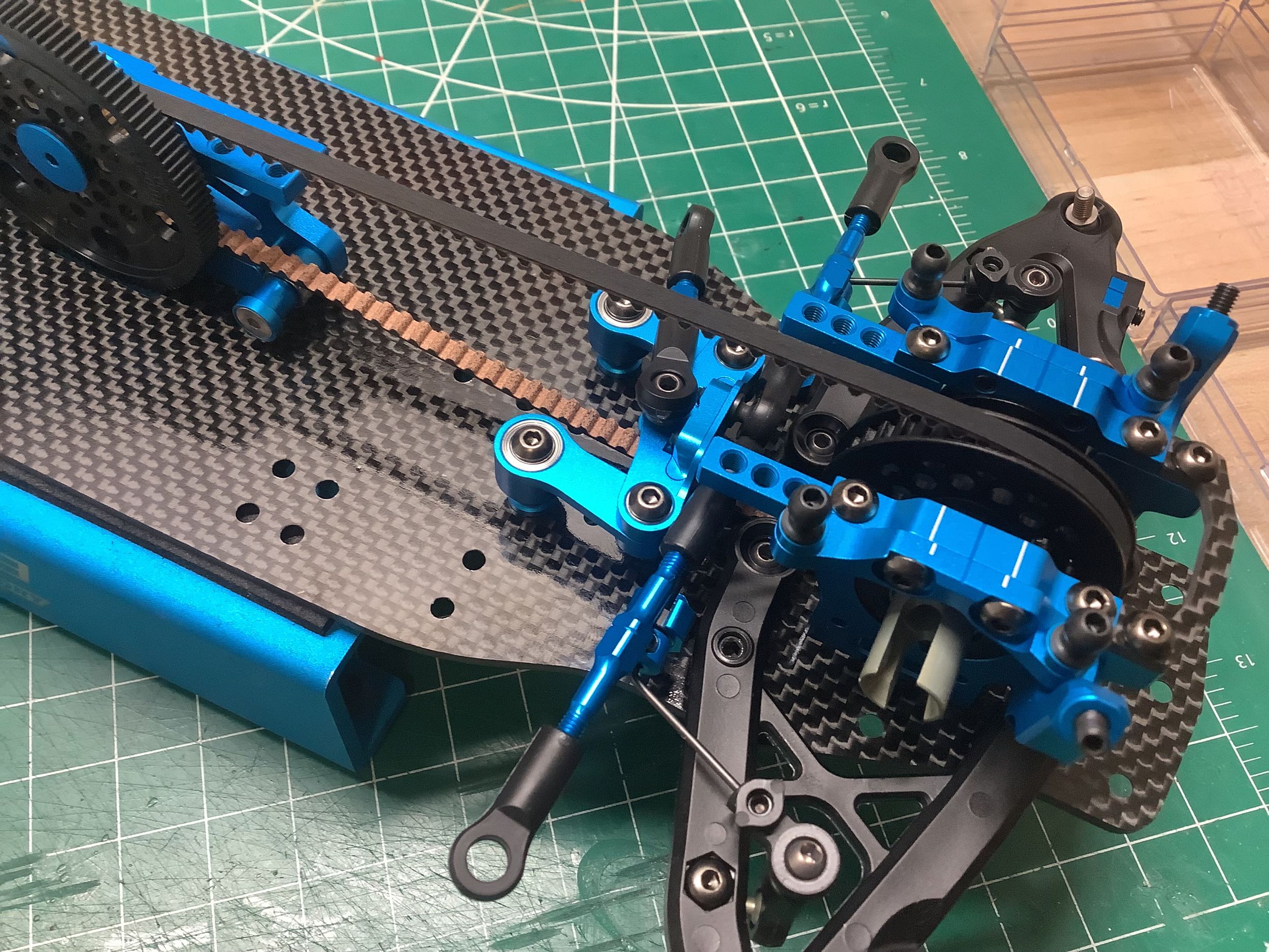
Here I've installed the steering on the chassis which is tricky to get
into place without fouling the belt or the bulkheads. You can see
that I've installed the turnbuckles backwards (right hand thread facing
the left side) which was hidden by the fact that the cranks were facing
the wrong
way in the previous image. I didn't notice until much later which
required quite a bit of disassembly. After all this time you'd
think I wouldn't make mistakes like this.
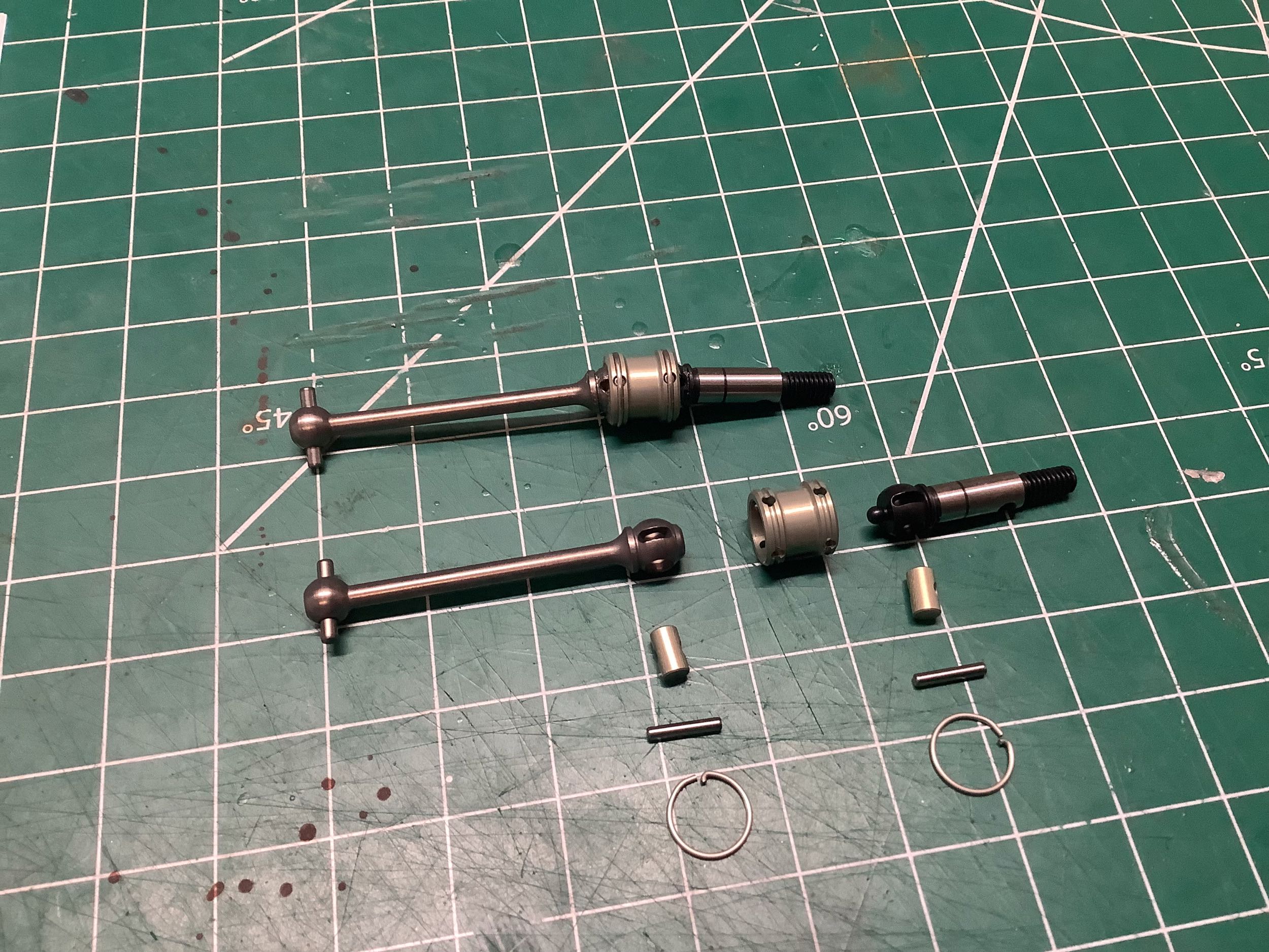
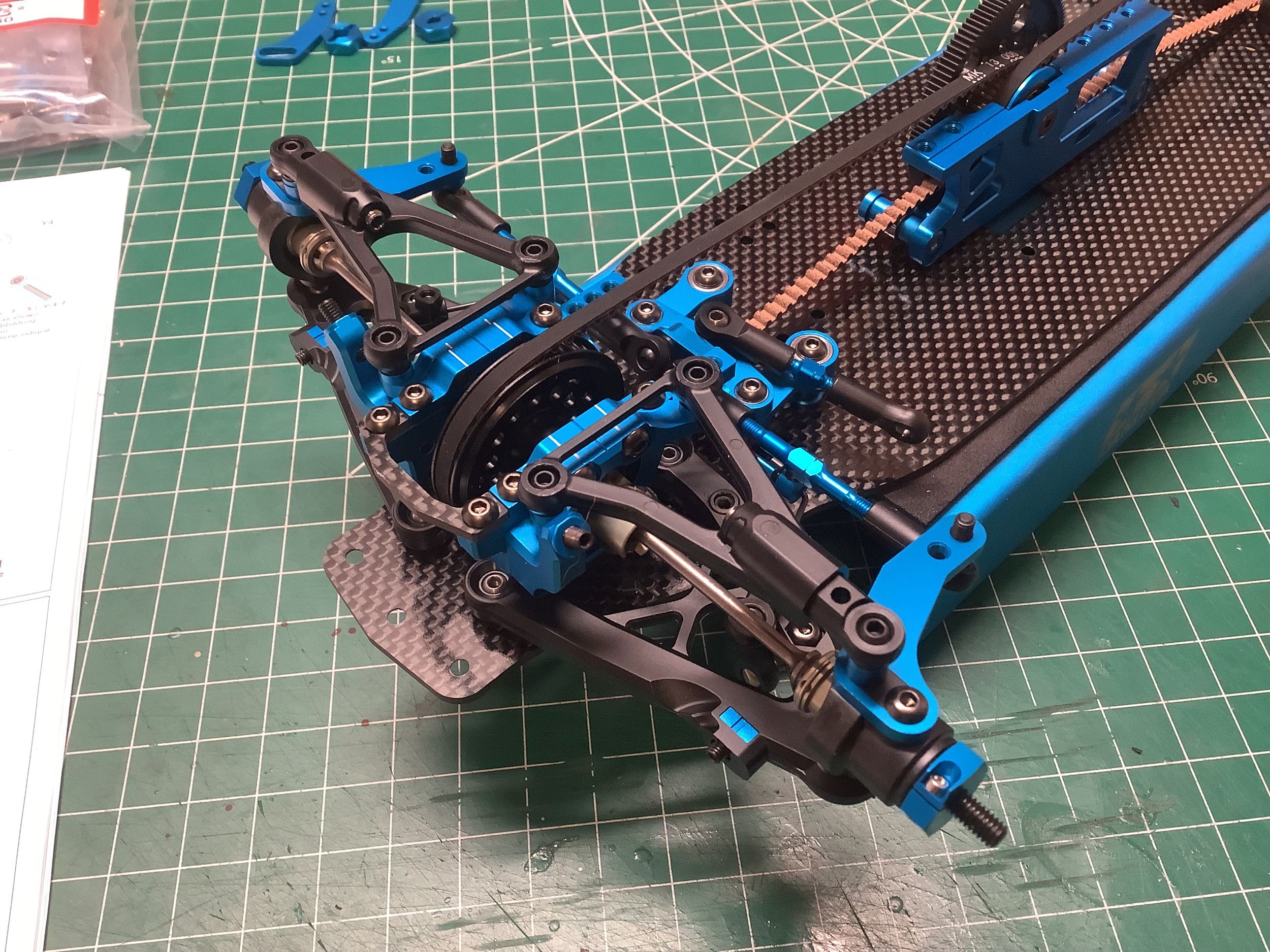
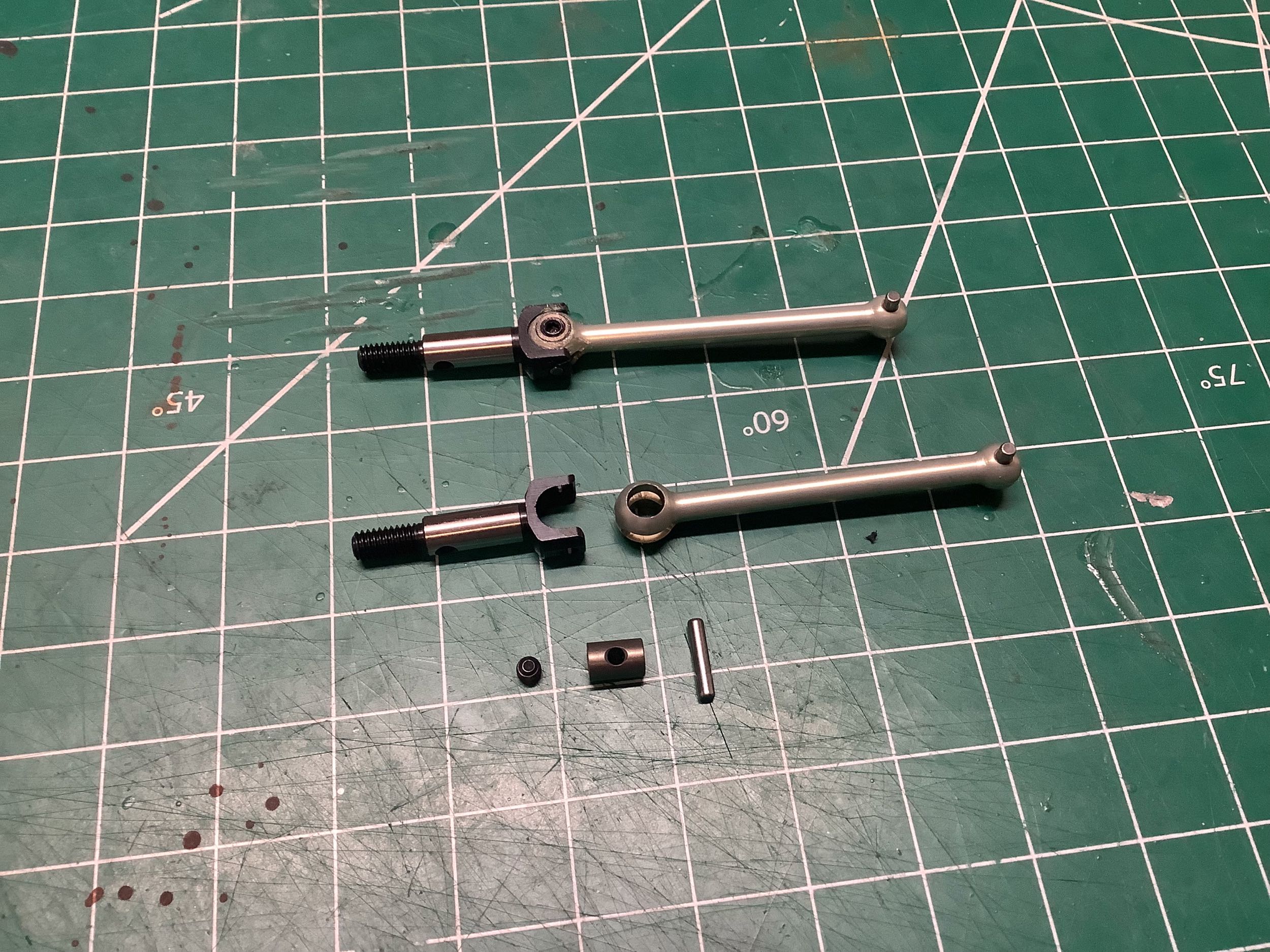
These front double cardan axles from hardware Bag C are almost just like
those from the TRF 420 except for being a millimeter longer. The
dogbone, axle, and barrels are steel and the collar is aluminum.
Step 26 assembles them on the left. The TRF 421X modified these by
replacing the plastic blade slider at the end (shown in the right hand
image) with little ball bearings instead. This allows the axle to
slide in and out of the drive cup without any friction during suspension
travel. Seems like a good efficiency upgrade, but also seems like
those tiny bearings will take a pounding since they are carrying all
the torque and braking forces. Time will tell if they are really
an improvement (but not for me since I don't have them). On the
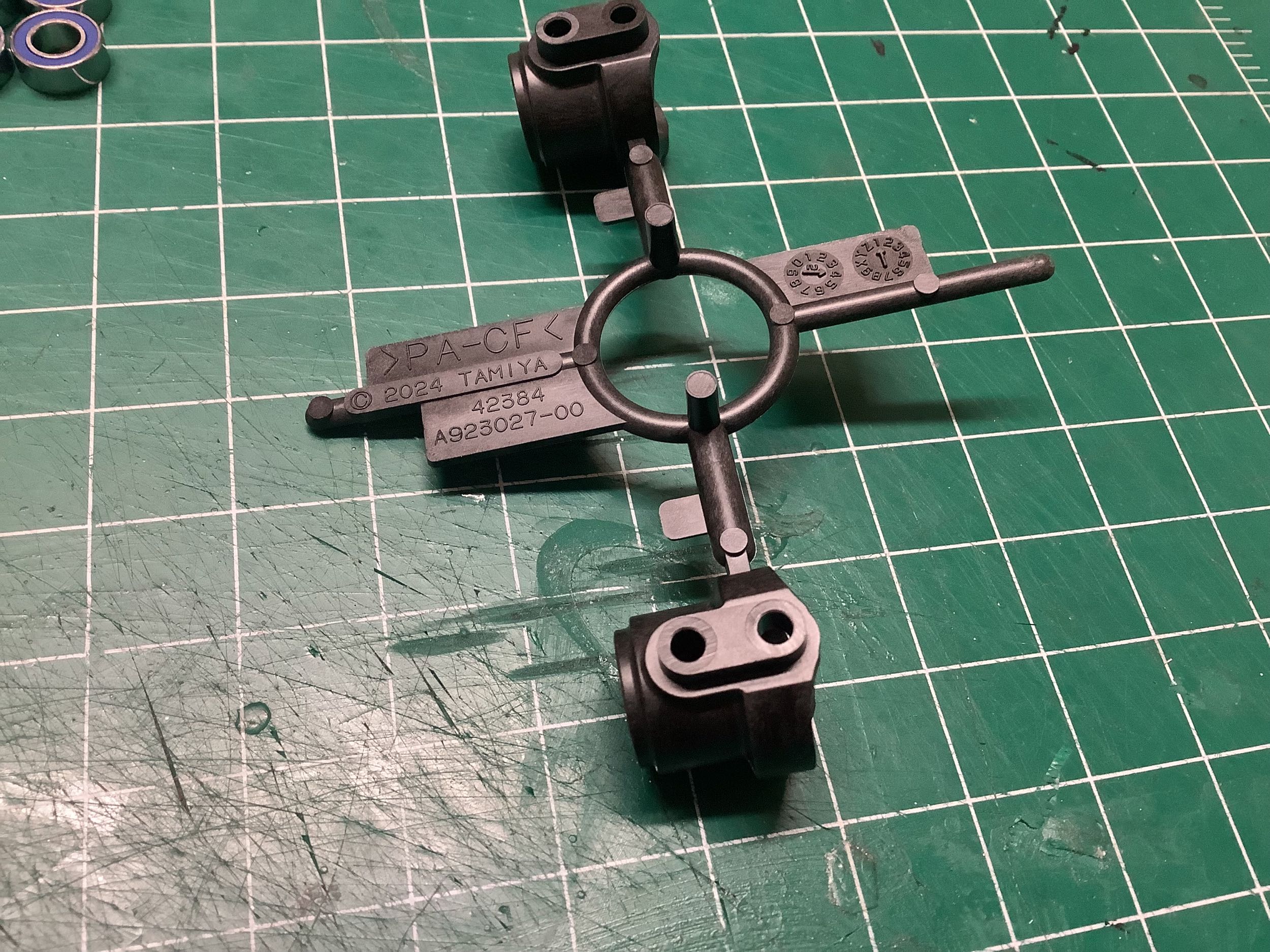
right is Step 27 (and part of Step 28) which assembles the front
steering knuckles. The uprights are the same part for all four
corners. The knuckle arms are separate aluminum parts which screw
into place and have two hole options for the steering link connection.
The outer one is used by default.
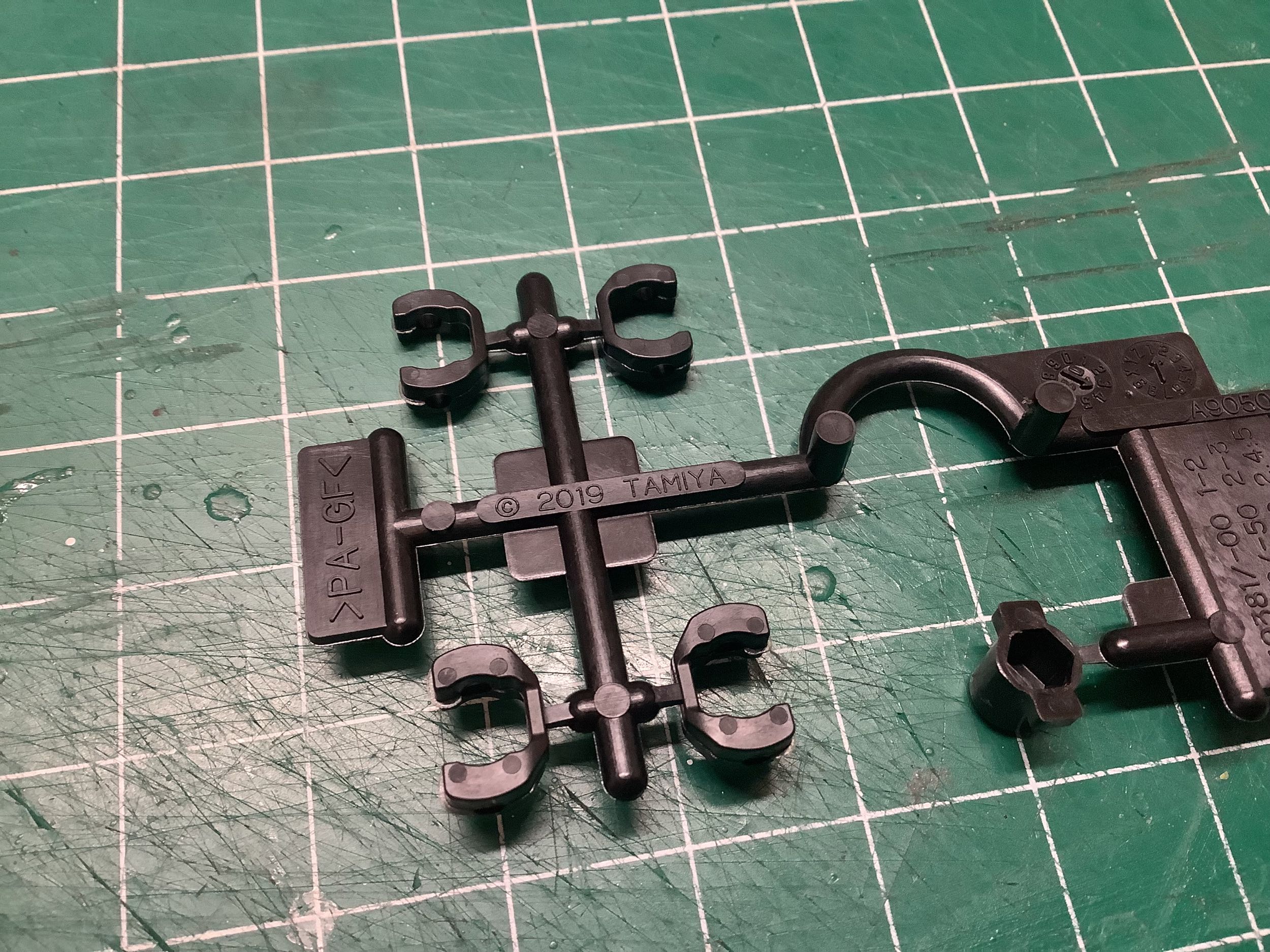
These little plastic parts that I call "blades" (I have no idea what the
proper name for them is) are made from glass filled Nylon while some
older models used Delrin. They fit extremely tight in the mating
drive cups. I had to sand them down to get them to slide at
all. The upright are carbon filled Nylon so they are nice and
stiff but hard to thread into.
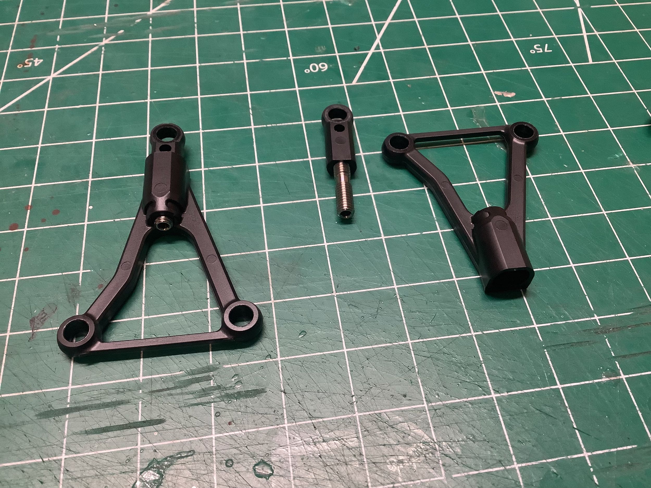
The upper arms are finally wishbone shaped! Why do I say
"finally"? Because no one would make a real car suspension the way
that RC touring cars used to do. By using a camber link that is
just pinned at each end, all thrust and drag forces need to be carried
by the lower arm. Since the axle is axle is above the lower arm,
this means the knuckle will always be trying to twist the arm (applying
torsion). This is a weak, sloppy way to design a suspension.
That's why real racing cars1 use
"double wishbone" with an upper and lower A-arm. This is not the
first Tamiya touring chassis to do such a thing though; the TC-01
chassis from 2020 did the same thing. Those upper arms, however,
were fixed length. The picture at the left shows how the length of
this arm can be adjusted with a 4mm screw (Step 28). This is
reverse threaded at one end and the rod end has flattened faces so it
can't spin inside the arm. The effect of this is that when you
insert a 2mm hex key into the screw from the back end of the joint, it
pulls both ends together. This allows both easy camber adjustment
and strong longitudinal support. Nice. Step 29 snaps these
arms onto the chassis, completing the front suspension. The ball
joints fit really tight, so using only your fingers is a
challenge. Using a tool will mar the parts though, so the
builder's body must be sacrificed for the greater good. Note that
camber, toe, and caster can all be adjusted without taking anything
apart. More subtle adjustments like roll center and toe gain must
be done with spacers. This is a nice suspension.
1I admit that cars with MacPherson strut
suspension have the same problem, so it does exist in the real
world. But no performance car would do this.
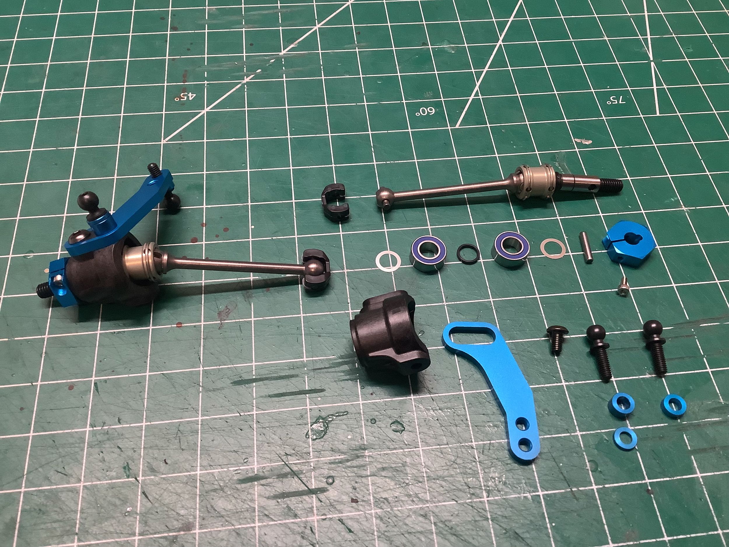
The rear axles have been modified since the TRF 420. Apart from
being 2mm longer, the axle stub now uses a C-shaped cup instead of a
hemispherical cup and a set screw instead of a cross pin. I
suppose this is a bit lighter. Unlike the front axles, these are
aluminum. Step 30 builds the axles, Steps 31 and 32 build the
knuckles, and Step 33 installs them. The rear uprights, knuckles,
and suspension arms are same parts used on the front suspension.
The only difference is that the inner steering link hole is used.
The rear could have used a fixed upright, of course, but that would have
required unique suspension arms that didn't match the front.
Using all the same parts makes carrying spares easier, and also makes it
easy to adjust rear toe without changing any parts.
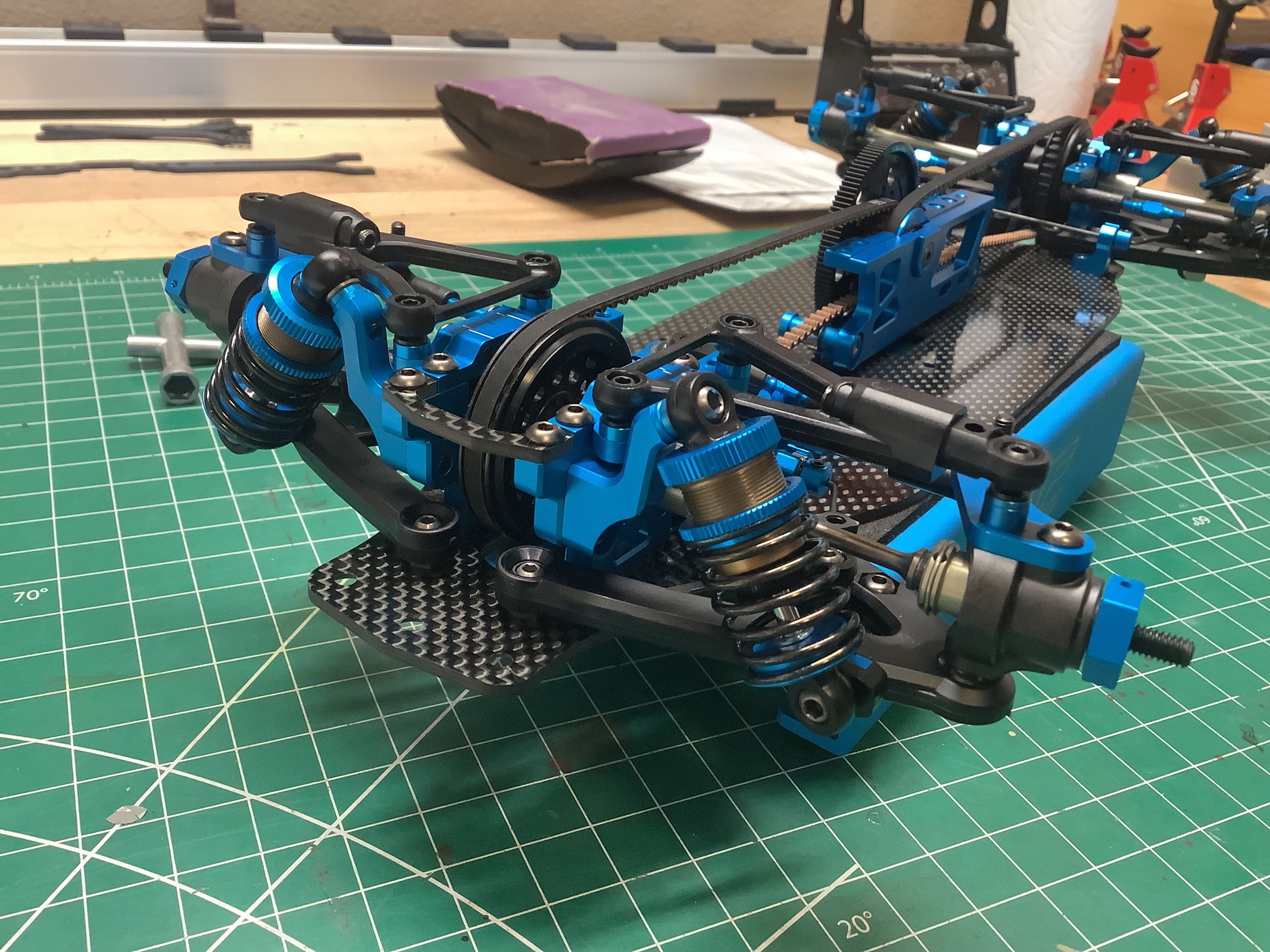
The "original" TRF shocks were 55mm in length and 10mm in inner
diameter. Too long and too skinny, you say? The "Short"
dampers went down to 51mm and the "Big Bore" dampers set the diameter up
to 10.5mm. These were two different damper sets though. The
TRF 419X went crazy and used "Super Short Big Bore" by decreasing the
length to 48.5mm and increasing the bore to 11.2mm. These were
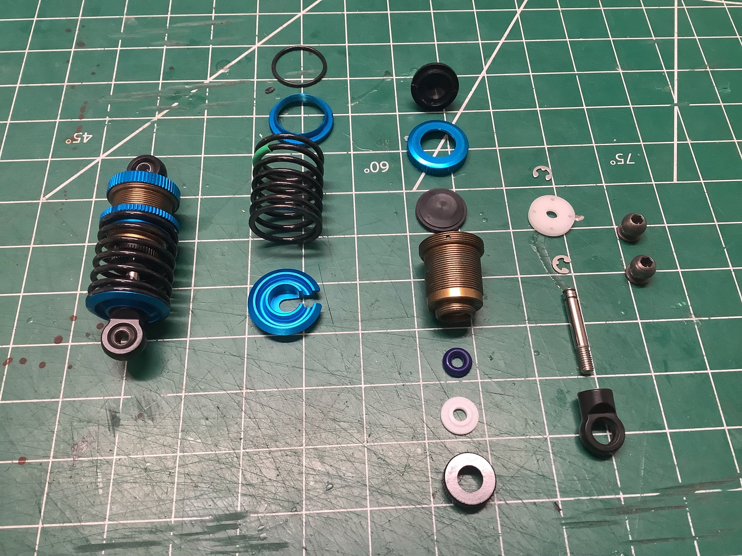
clearly the ultimate. Right? Wrong. The TRF 421
introduced the "Ultra Short Big Bore" which further decrease the length
to 43mm, while retaining the same 20mm springs. In the picture on
the left which shows an exploded view of the dampers (Steps 34-36 from
hardware Bag D), see how the lower spring perch needed to be designed
really flat with an inset for the rod end to add as little length as
possible. Another change is that the bladder seal actually sits
inside the bore instead of overlapping it, allowing the use of an
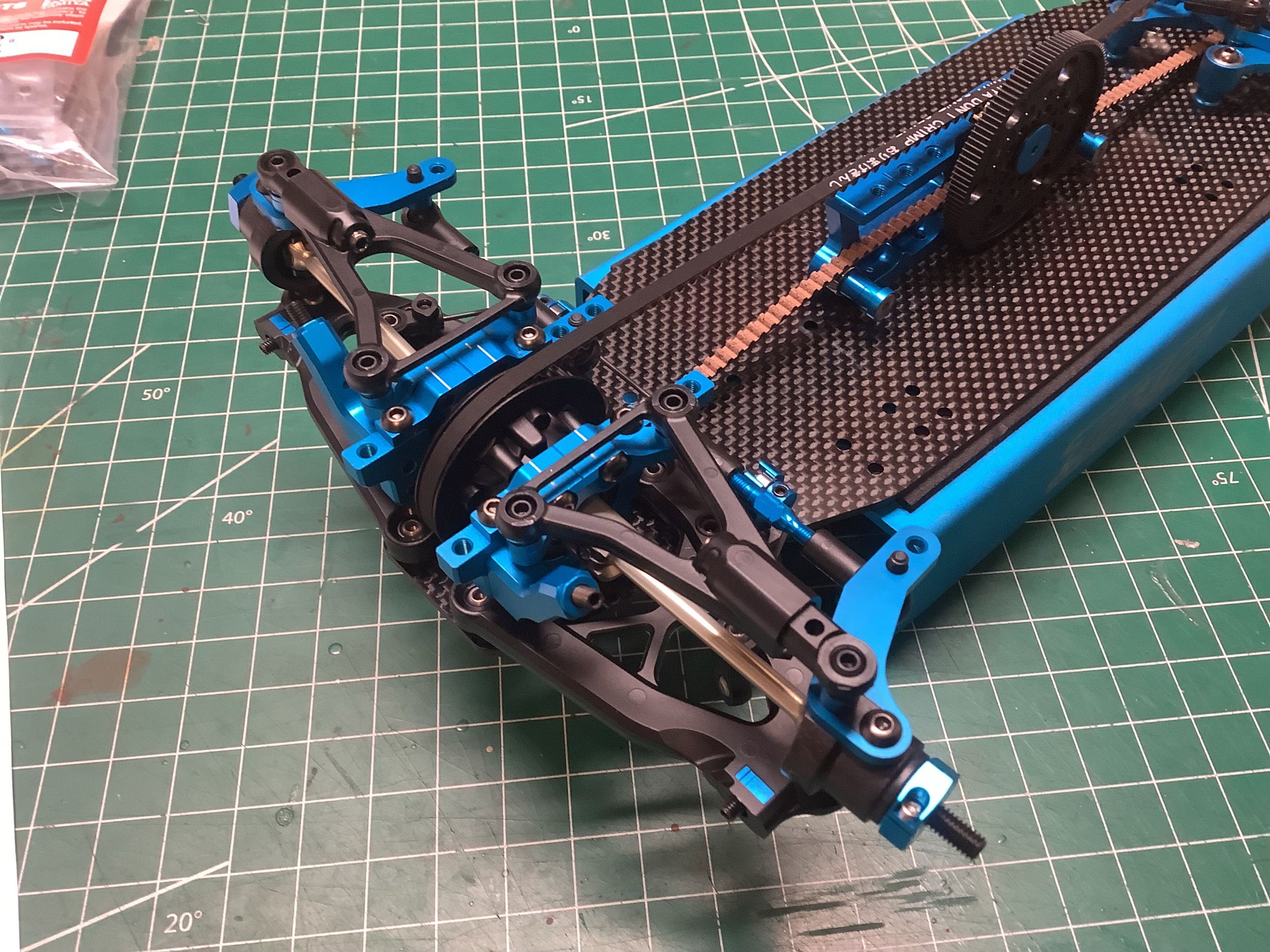
extremely flat cylinder cap. These dampers use the HL (High
Lubrication) coating on the cylinder, anodized aluminum spring perches
and caps, and Delrin pistons. The reinforced V parts (rod ends)
with 5.8mm balls are carried forward from the TRF 420. You can see
them installed on the right and note how they barely protrude above the
bulkheads. Very compact, but also very little travel. It's
my understanding that modern chassis use a combination of suspension
movement and chassis flex to absorb deviations in the road surface
rather than relying on the suspension alone. Maybe that's why this
works. The rear shocks are exactly the same as the front except
for the default preload adjustment.
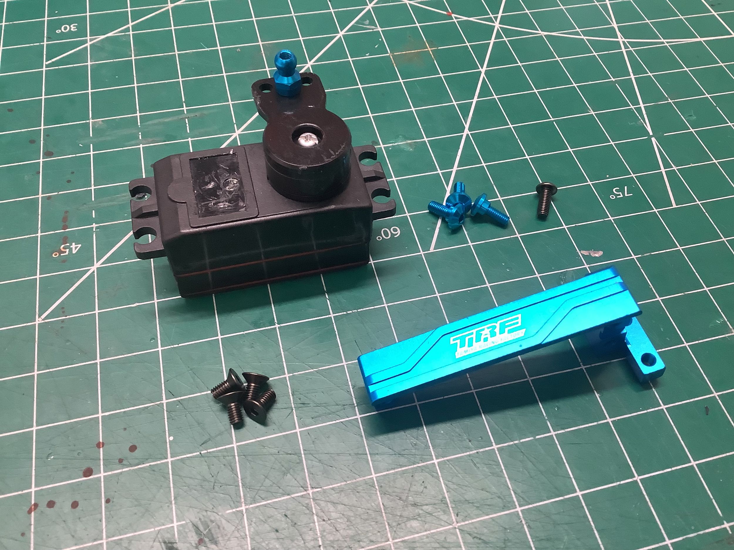
This chassis uses the now standard cantilevered servo mount introduced
with the TRF 417 V5, but the part itself is not common to any previous
models. Step 37 opens hardware Bag E and assembles the high torque
servo saver (but no aluminum horn) to a required low profile
servo. I was able to get away with a regular servo because I don't
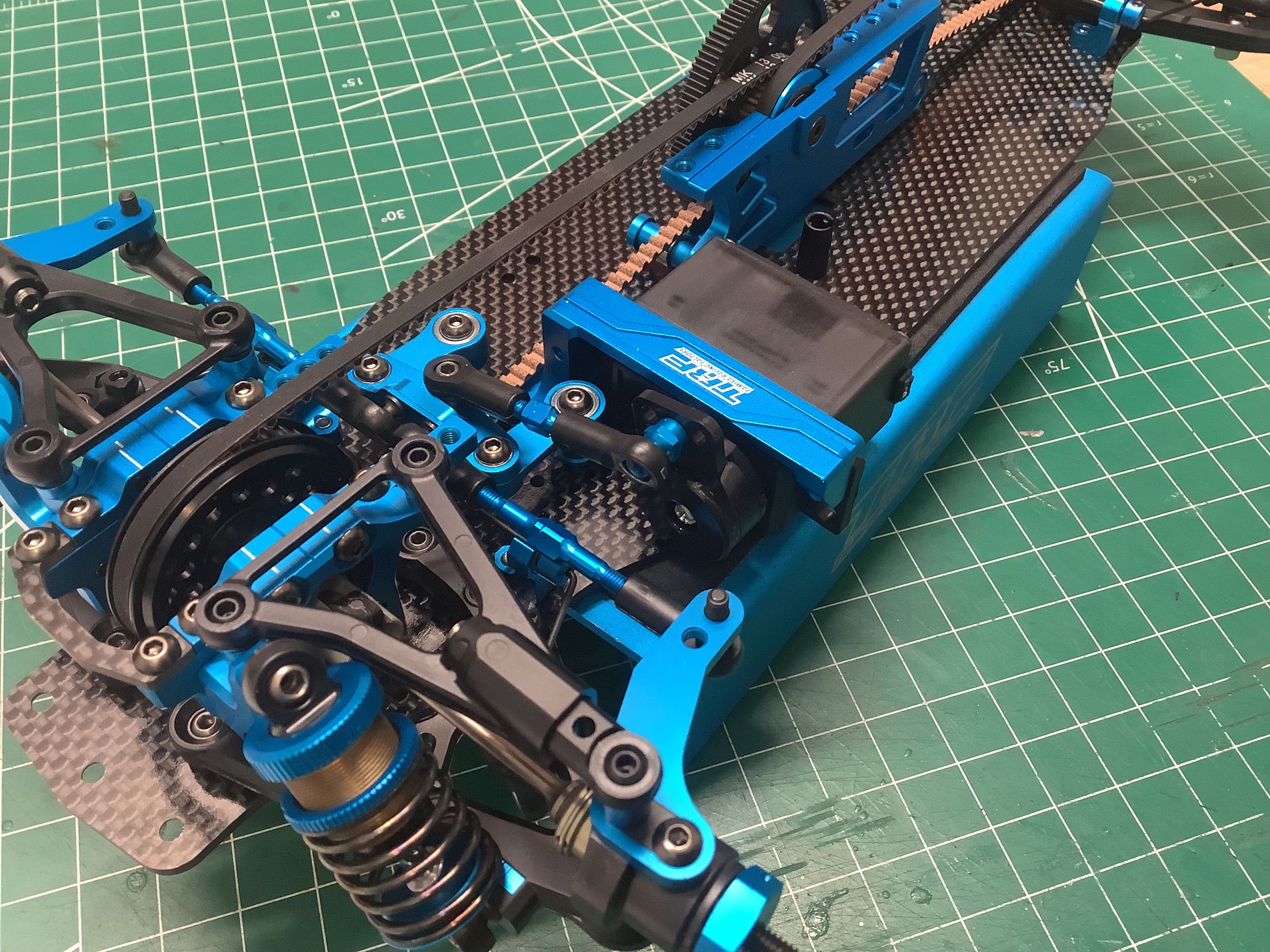
need room for any other electronics. Step 38 installs the servo
mount onto the chassis along with an antenna tube (which I later removed
to make way for the fan mount).
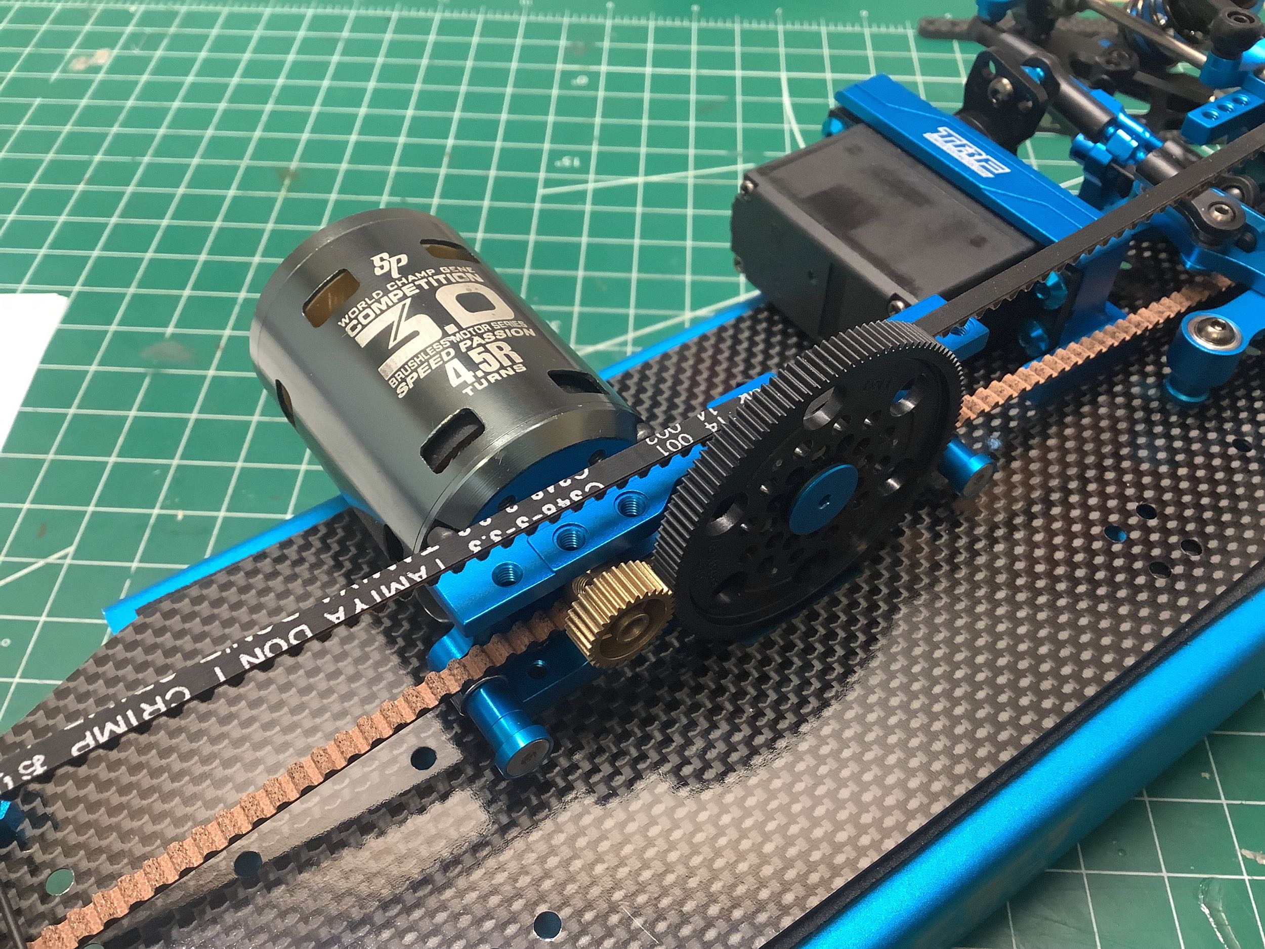
Step 39 installs the motor and the kit supplied 30T pinion. Only
brushless motors can be used because the mounting points are on the
bottom and line up with 2 adjacent screw holes in a 6 hole
pattern. With the default 116T spur, pinions from 26T-39T can be
accommodated. That's a pretty big range. Optional 113T of
111T spurs are available that push the pinion range up to 40T. The
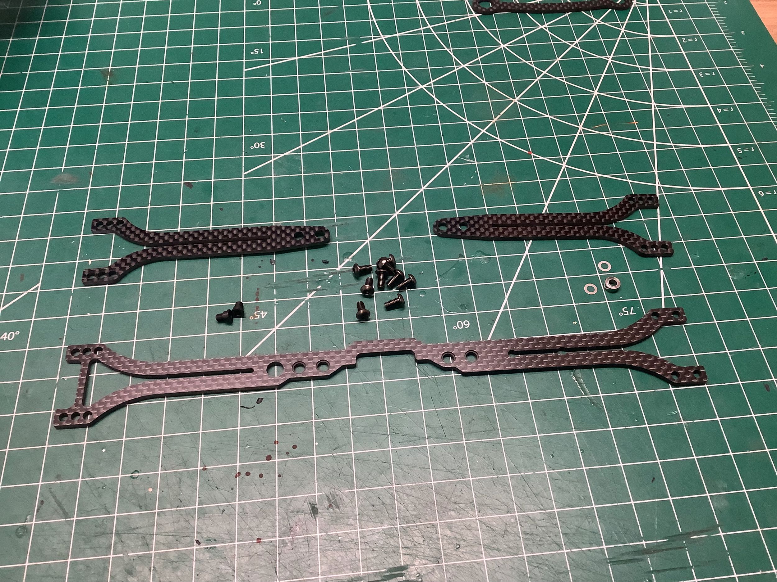
kit comes with two upper deck options: a single carbon plate that spans
the front and rear bulkheads, or a split deck that connects each end to
the center but does not span. I chose the single option. If
you zoom in on the picture, you can see the unique little step screws
that are used in the center bulkhead to attach the upper deck but still
allow it to pivot. The even larger hole used on the center
bulkhead uses a bearing for even more freedom.
Step 40 installs the upper deck and would also take care of the ESC and
receiver if I was using them. The picture on the right shows a
close-up of those special attachments of the upper bulkhead to the
center bulkhead discussed previously. The step screws can be
installed in optional hole locations or not at all.
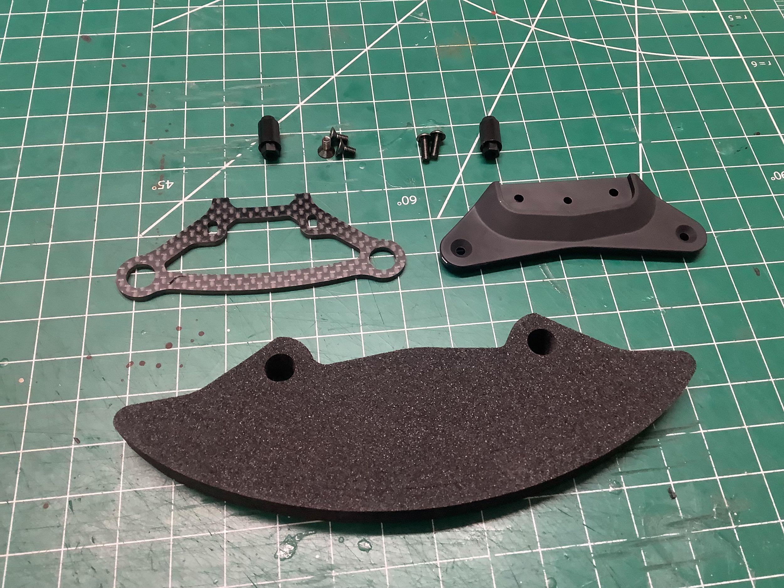
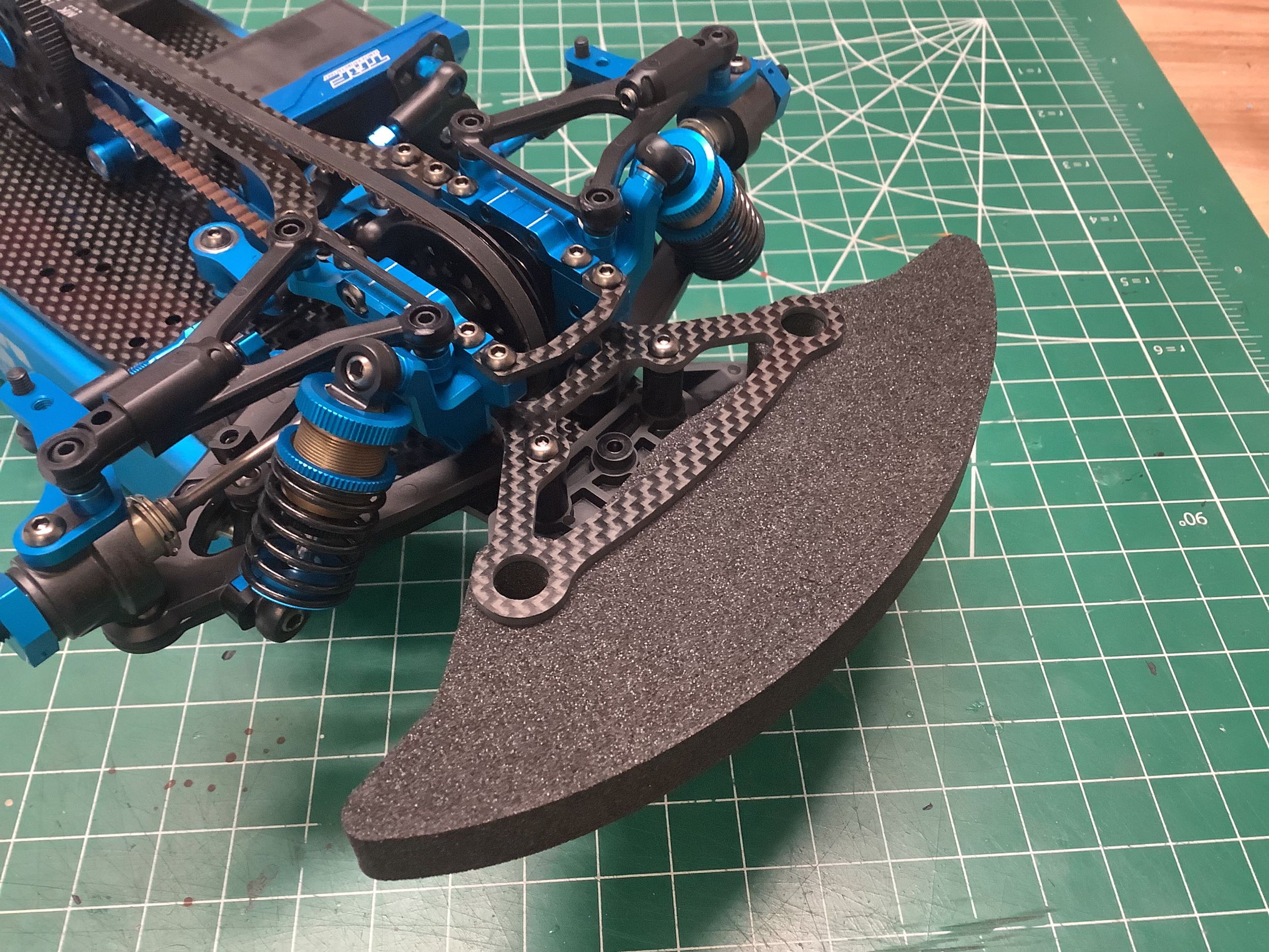
Steps 41 and 42 install the front foam bumper. The lower bracket
is plastic and the upper is carbon with holes for the body posts.
The foam bumper itself is similar in profile to the one from the TRF
420, but now has precut slots that be be punched out (see later photo).
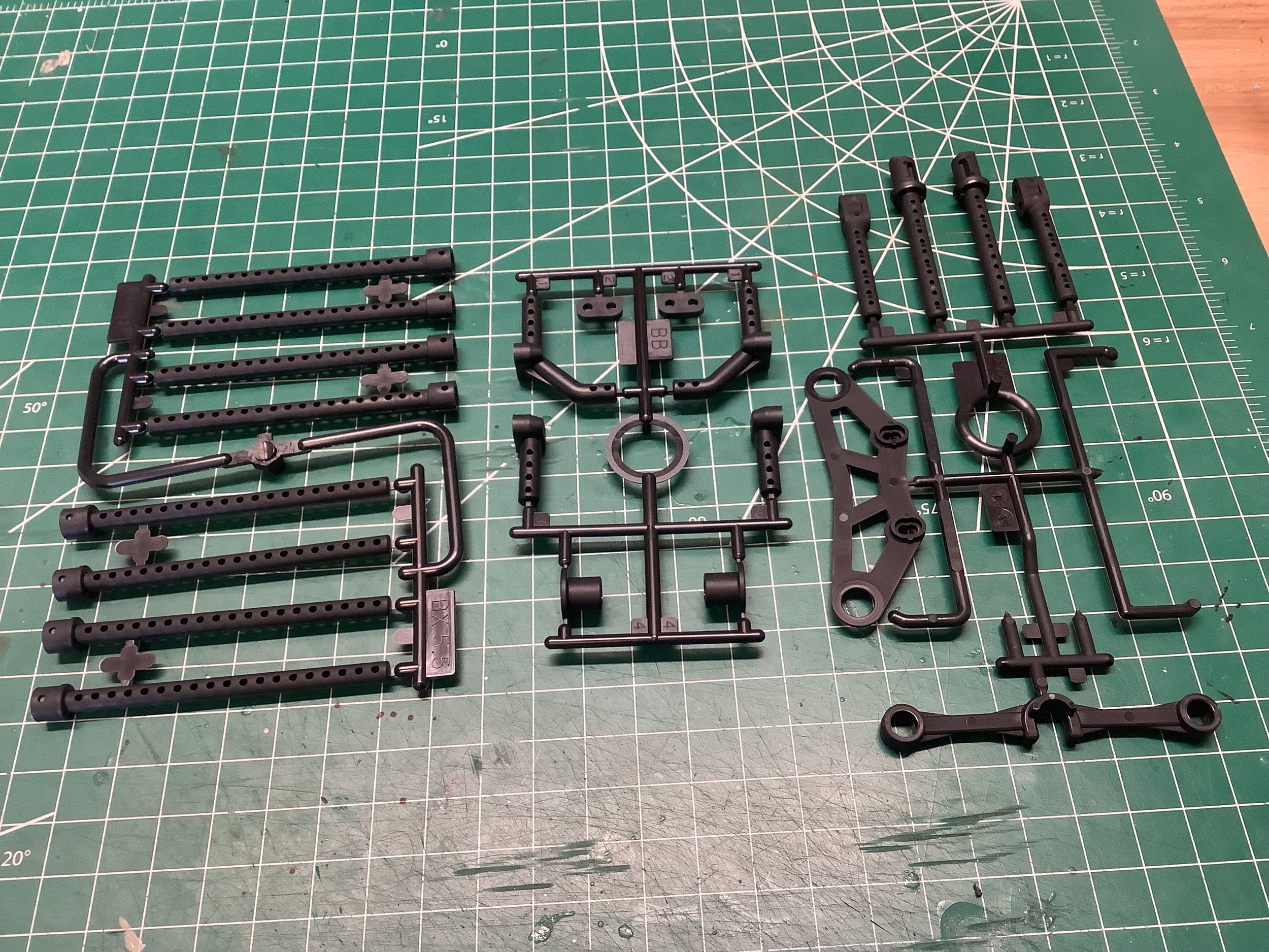
There are a lot of different body posts included with this chassis, but
most are not used. The B parts (far right) are used for the front
posts (Step 43). The BB parts (center) are used for the rear
facing posts which some modern bodies use. The BX parts (far left)
contain both 5.5mm and 6mm options for the rear posts. The larger
ones are used by default (2 of the 8 on the sprue).
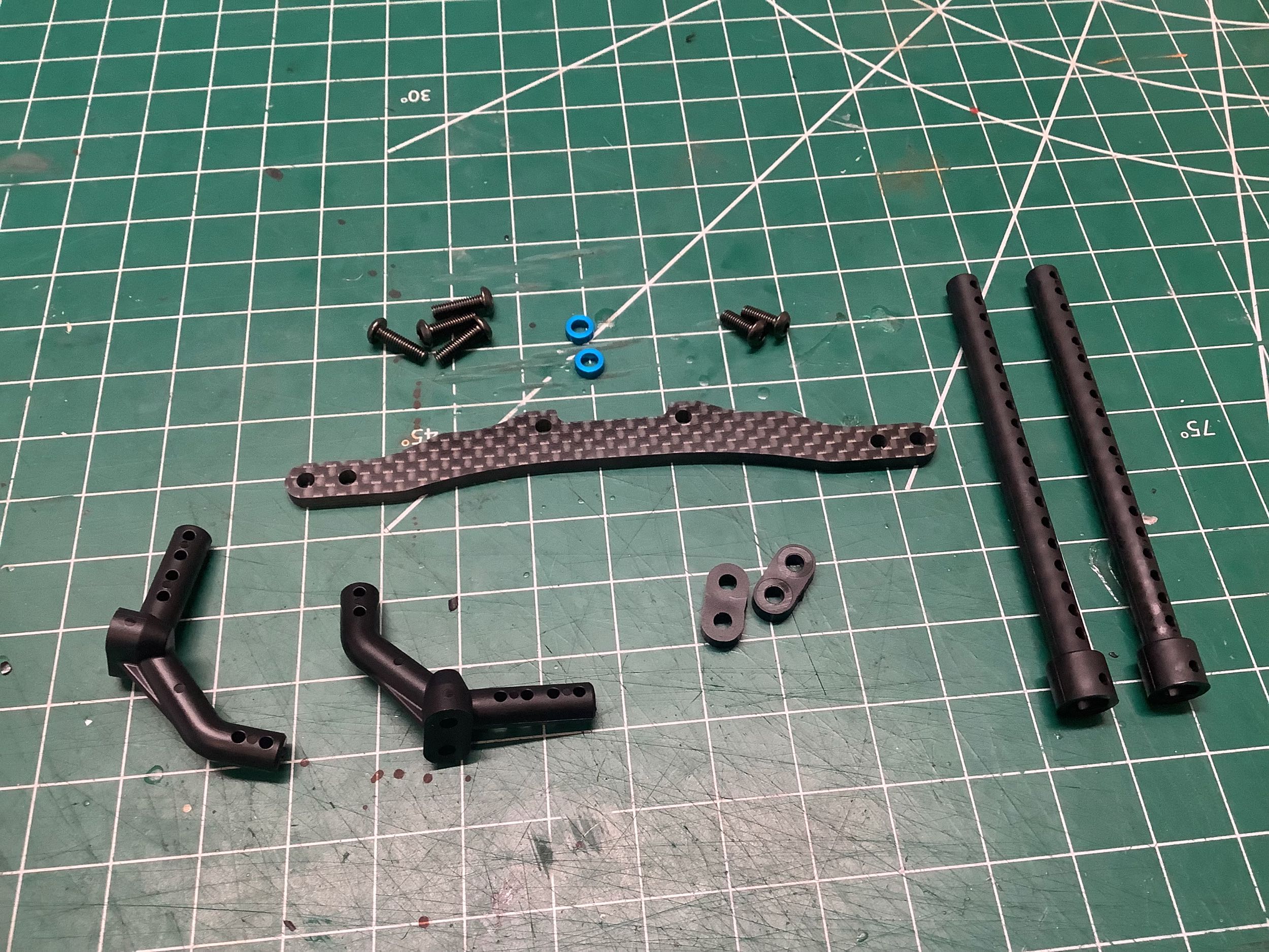
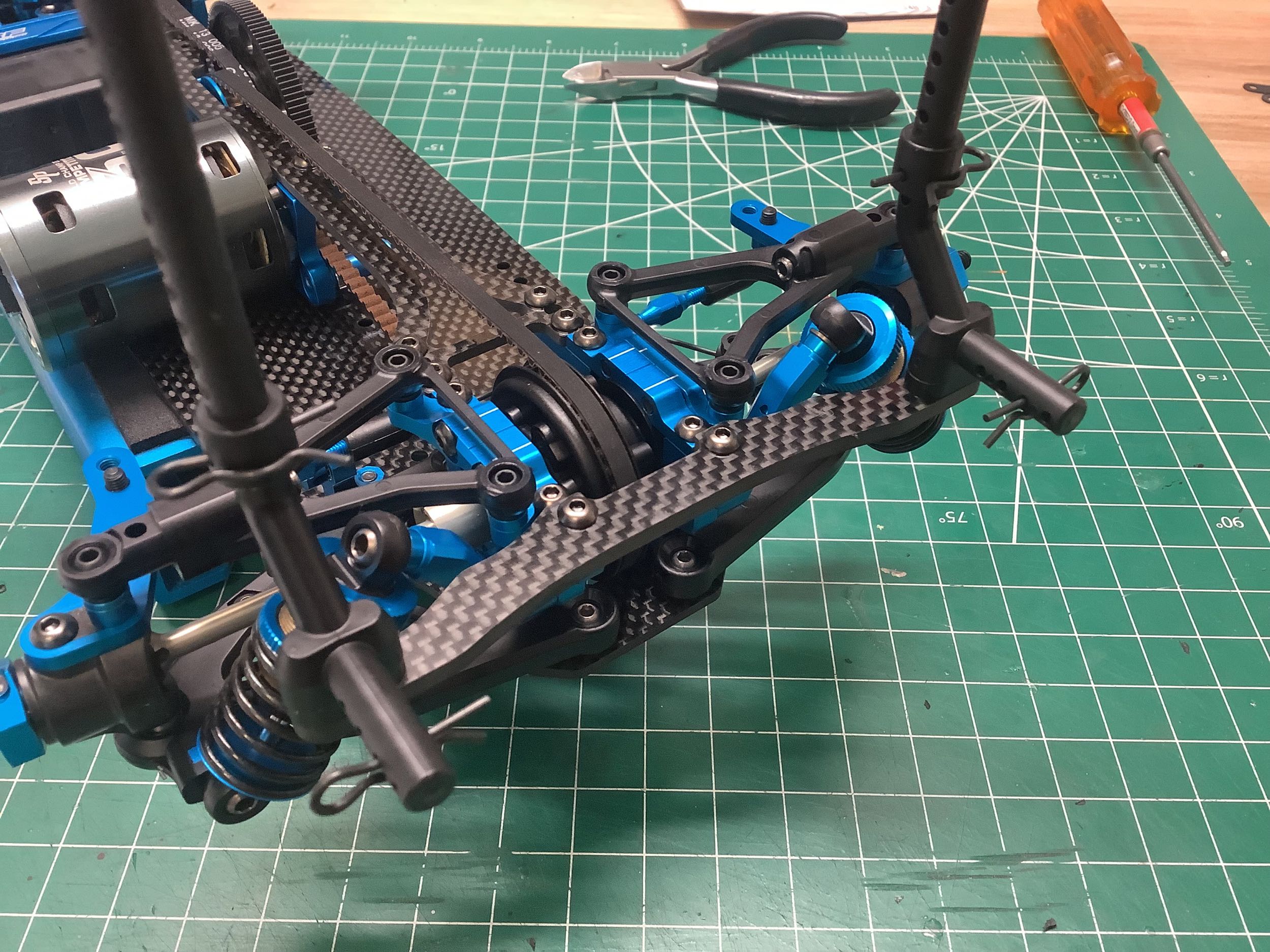
Step 44 assembles the rear body posts to the rear stay which also
doubles as a bulkhead cross member. The taller vertical posts are
optional if you are using a body that makes use of the rear posts.
Steps 46 and 47 install the battery clips. I'm very happy to see
that this chassis doesn't require any tape to install the battery,
something Tamiya did away with on the TRF 420X. The kit includes
parts for both the standard Tamiya Li-Fe battery and other more normal
types. Note that the configuration shown in the instructions did
not actually fit my standard hard pack though, so I had to do some
mixing and matching. Interestingly, the long screws used to secure
the battery clips are titanium.
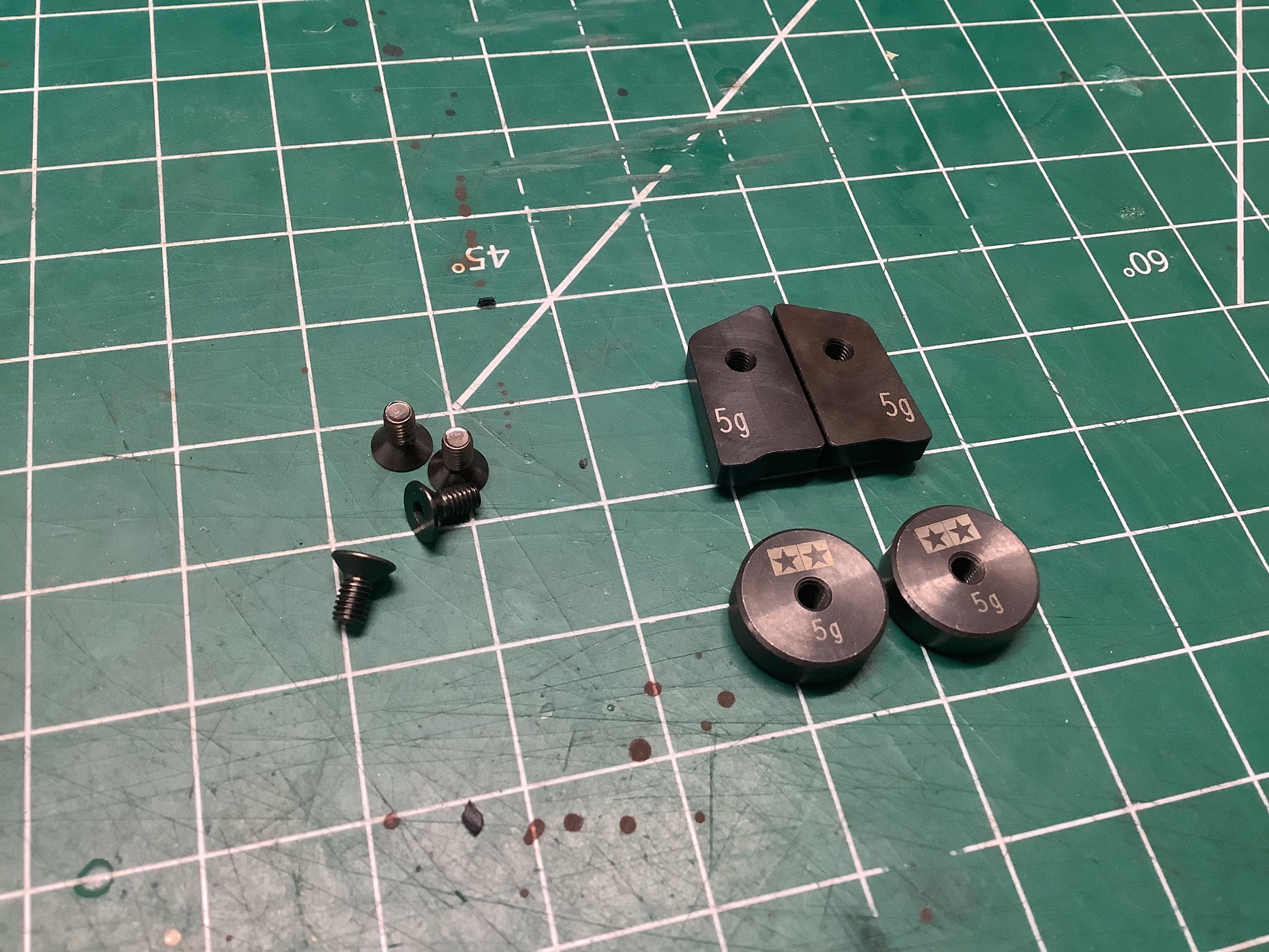
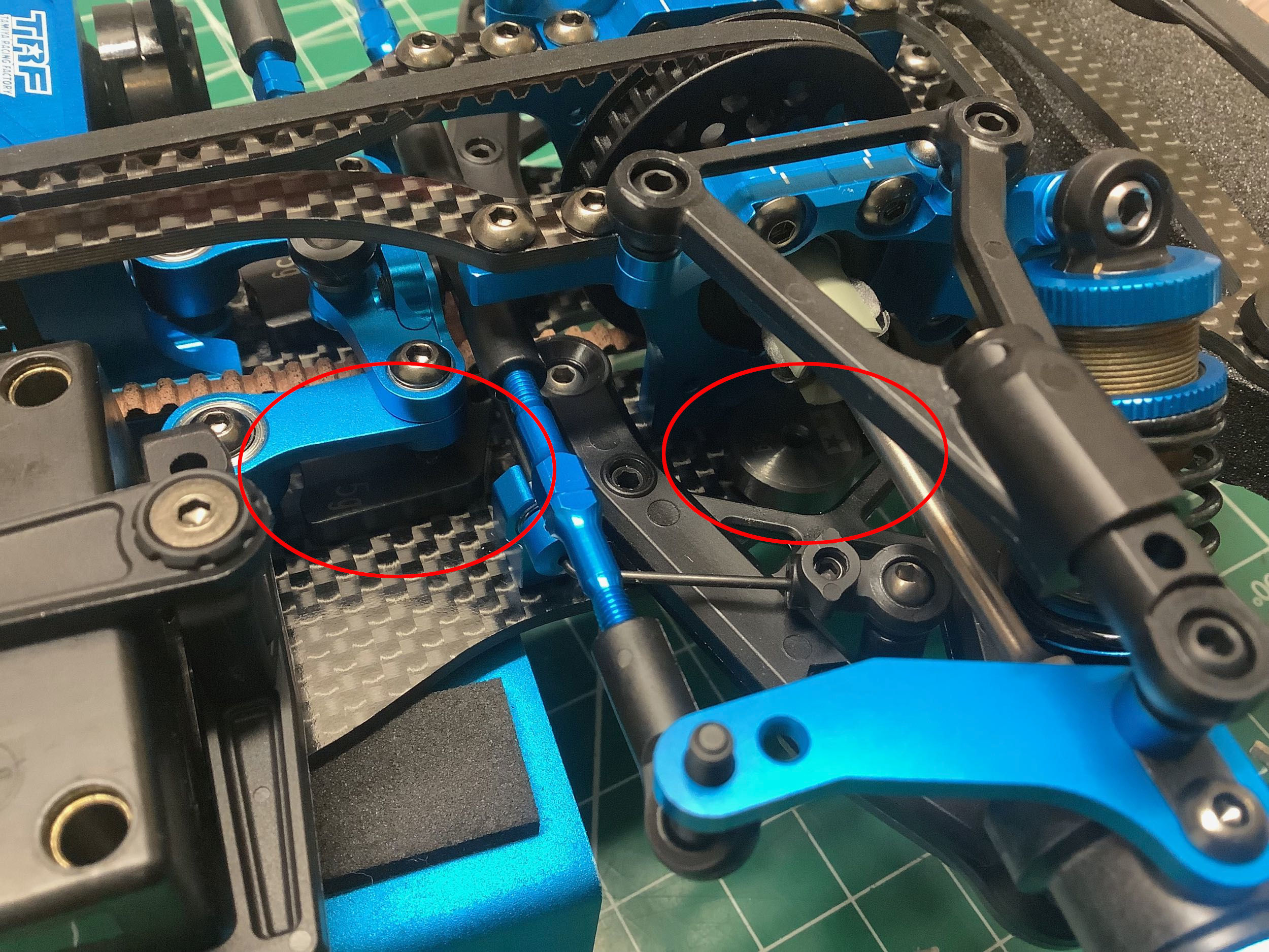
From this point one, everything I'm installing was optional. The
picture on the right shows the four different 5g ballast weights that
can be used. I've circled their locations on the right. The
round weights are hidden under the lower suspension arms, and the
trapezoidal weights go under the steering cranks. The TRF 421X
also added a battery weight for the lighter Tamiya batteries.
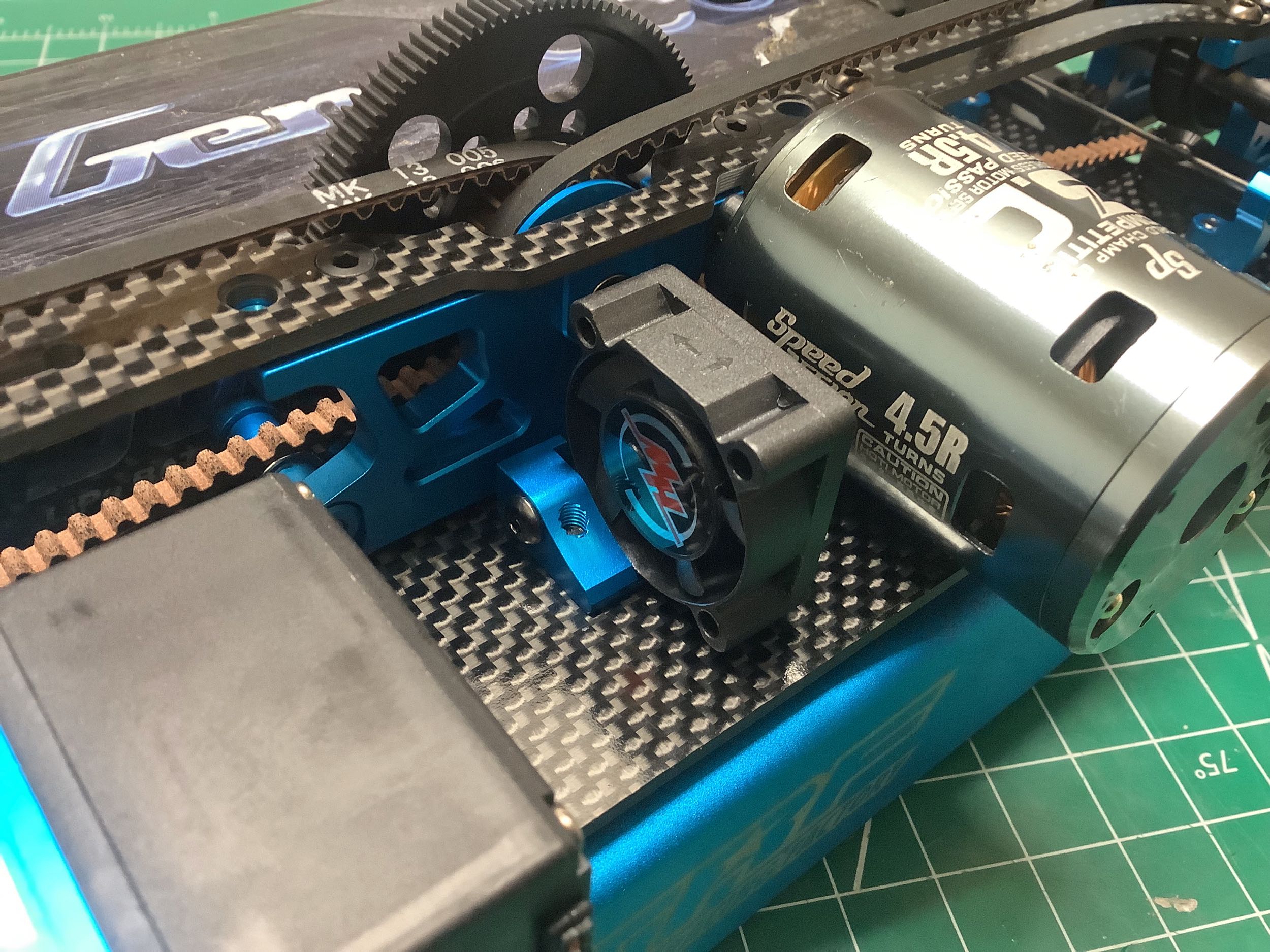
Here's an optional fan mount which I took the opportunity to
install. Using it further reduces the space for other
electronics. The TRF 421X replaced this with a version with an
integrated receiver tray. I also installed a transponder mount
between the front body posts as shown on the right.
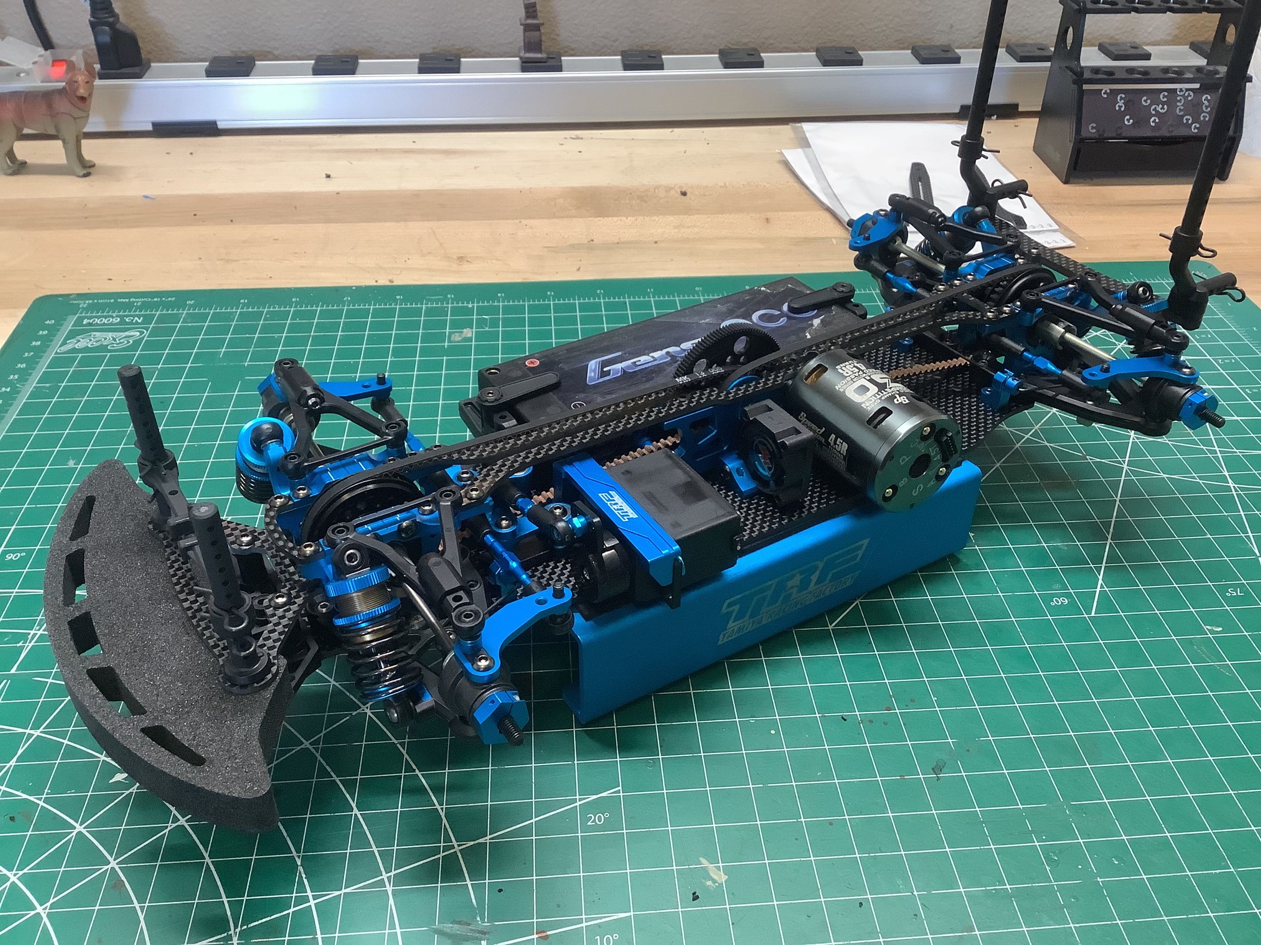
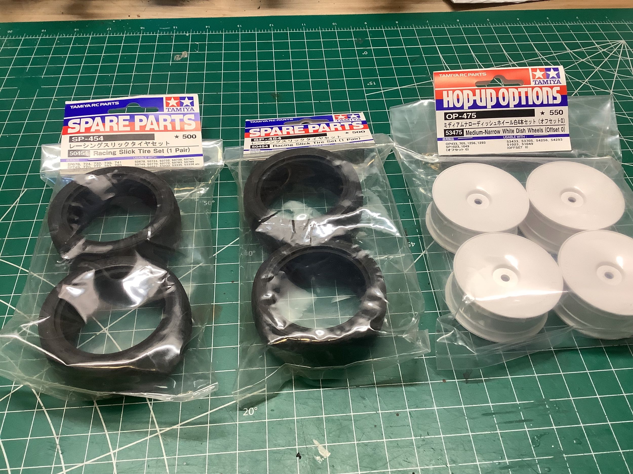
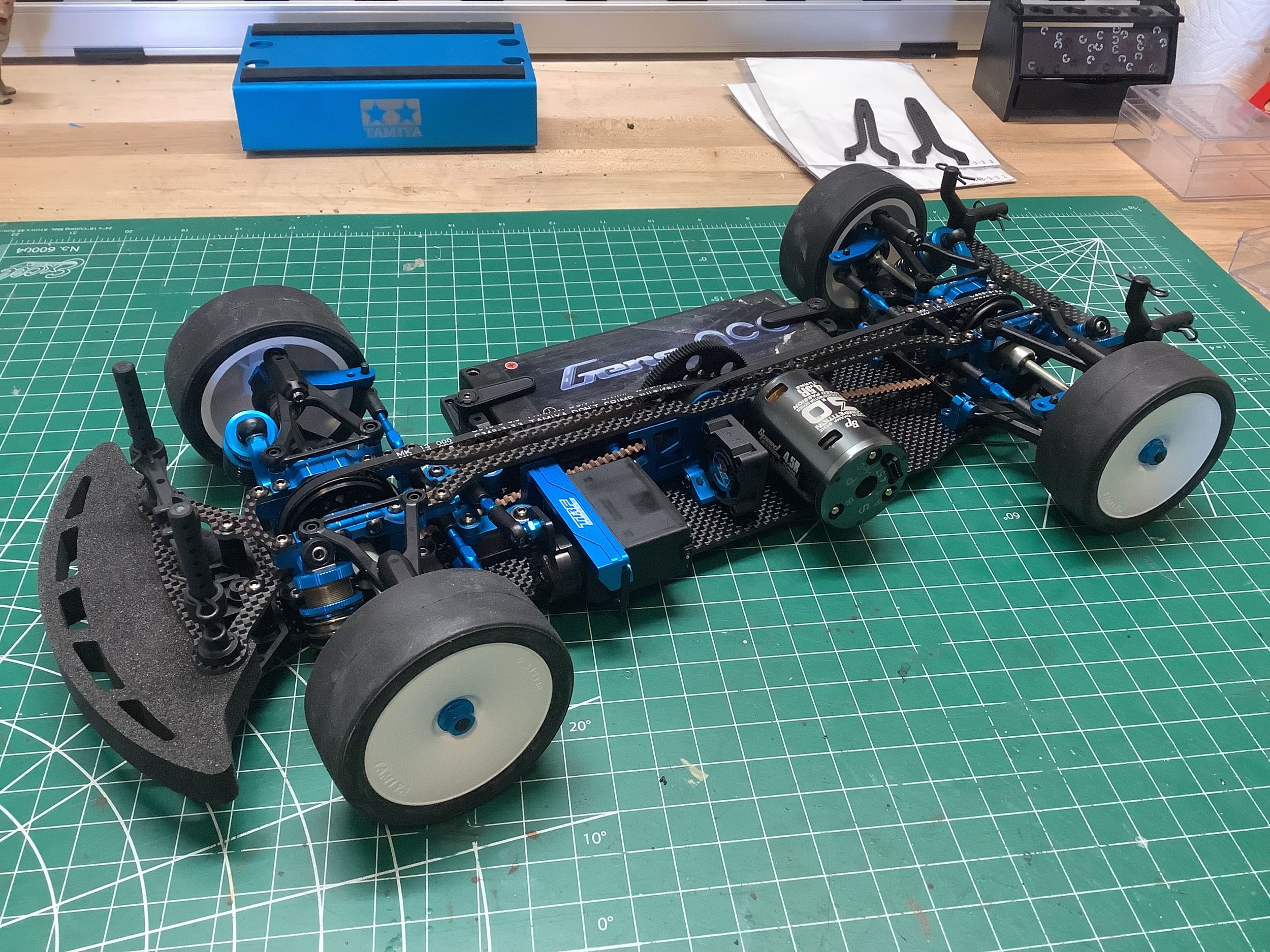
No wheels or tires were included with the model so I installed some
standard 0 offset dish wheels and slick tires. This completes the
chassis!
©2026 Eric Albrecht