TW-715 Project
Page 4: Building the Axles
The axles come pre-assembled in the box which theoretically means you
don't need to re-build them. I can't abide anything I didn't build
myself so I completely tore them down and it's a good thing I did
because there were a number of problems. The instruction videos
have no content at all for the axles; they just assume the axles are
already assembled. This means you are on your own figuring out how
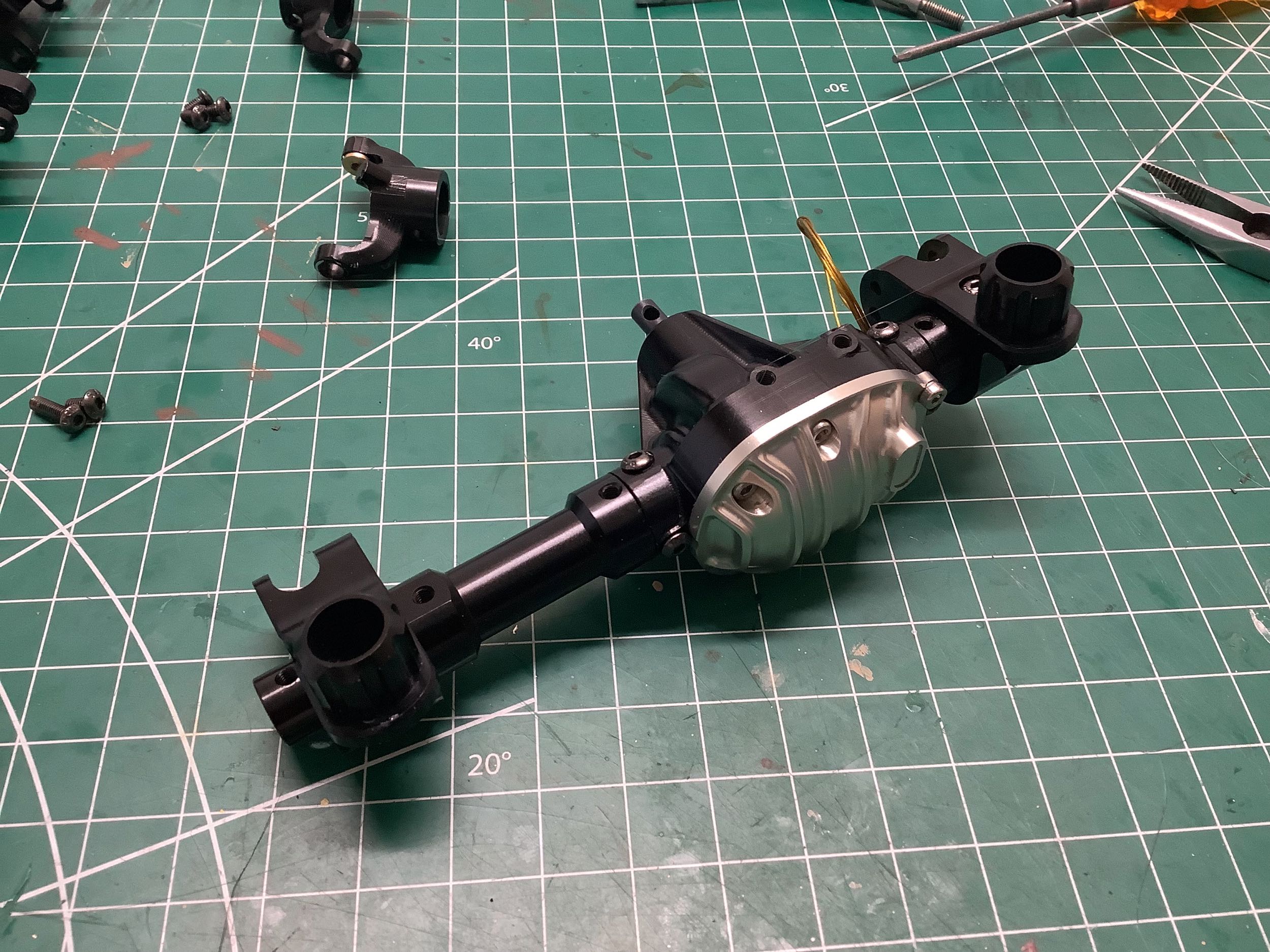
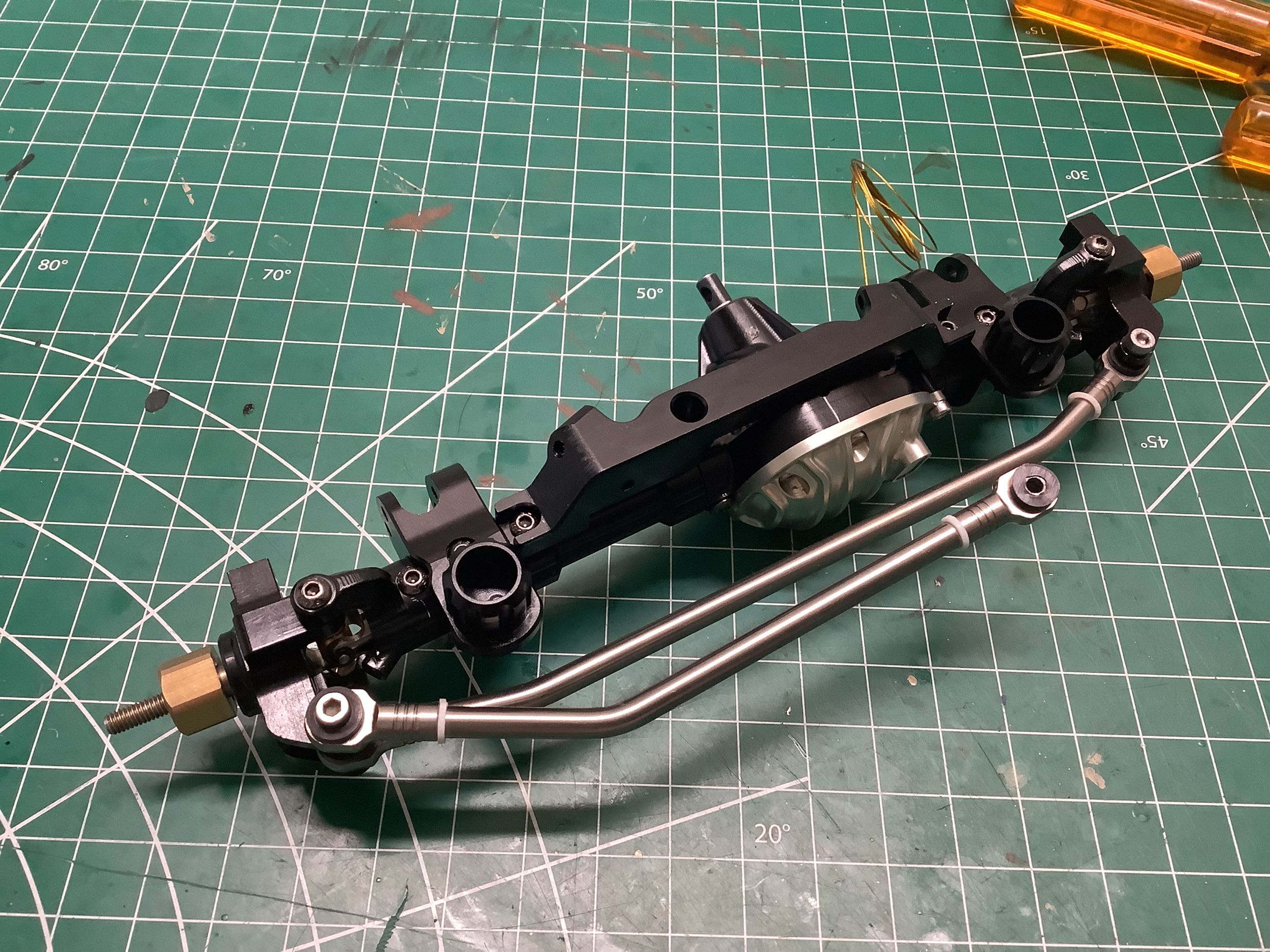
they come apart, function, and go back together. I photographed
the front axle as it came out of the box for reference as shown on the
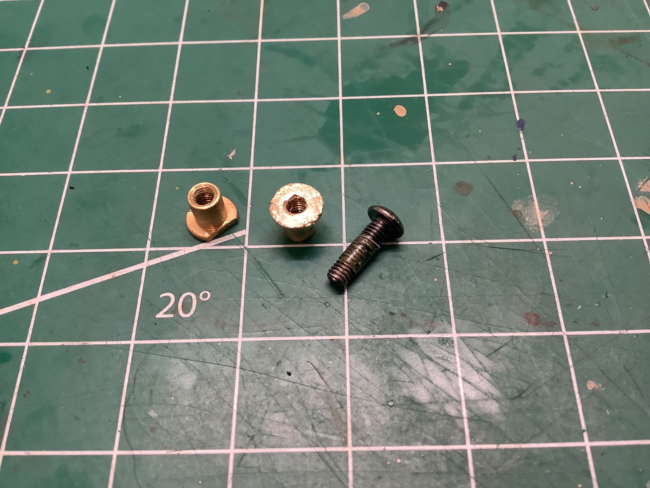
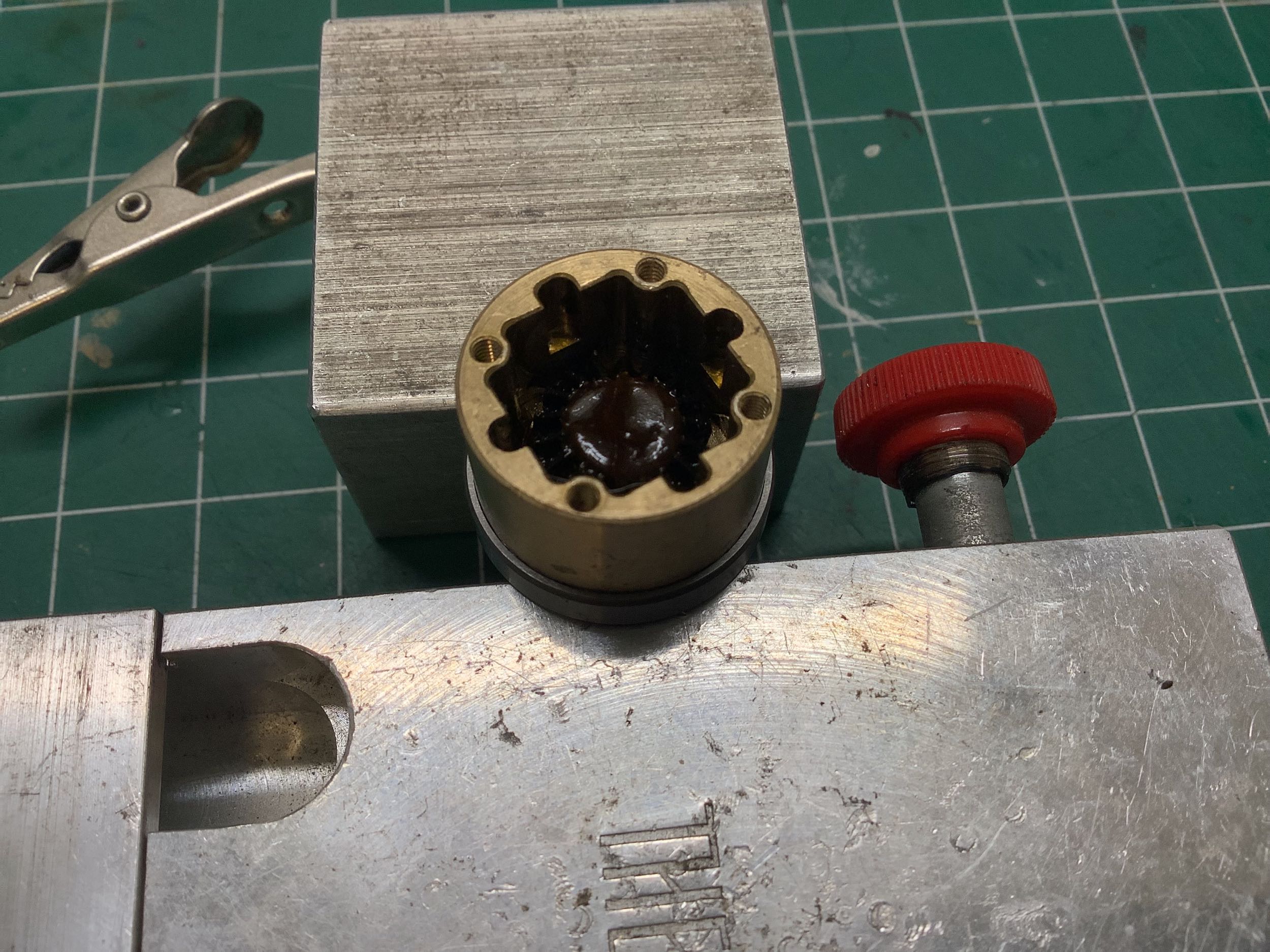
left. Disassembly took over an hour primarily because of the
threaded kingpin bushing shown on the right. Some of the bushings
had flats on them as shown which made it easy to grab them with a wrench
and remove the mating bolt. One of them did not have flats so I
had to try to hold it with a needle nose pliers which would have been OK
if not for the fact that this particular mating bolt was so slathered
with thread lock that it wouldn't turn at all (zoom in to see the
compound remaining on the threads). I ended up brutalizing the
bushing getting it apart. Luckily it will be completely hidden
once re-assembled.
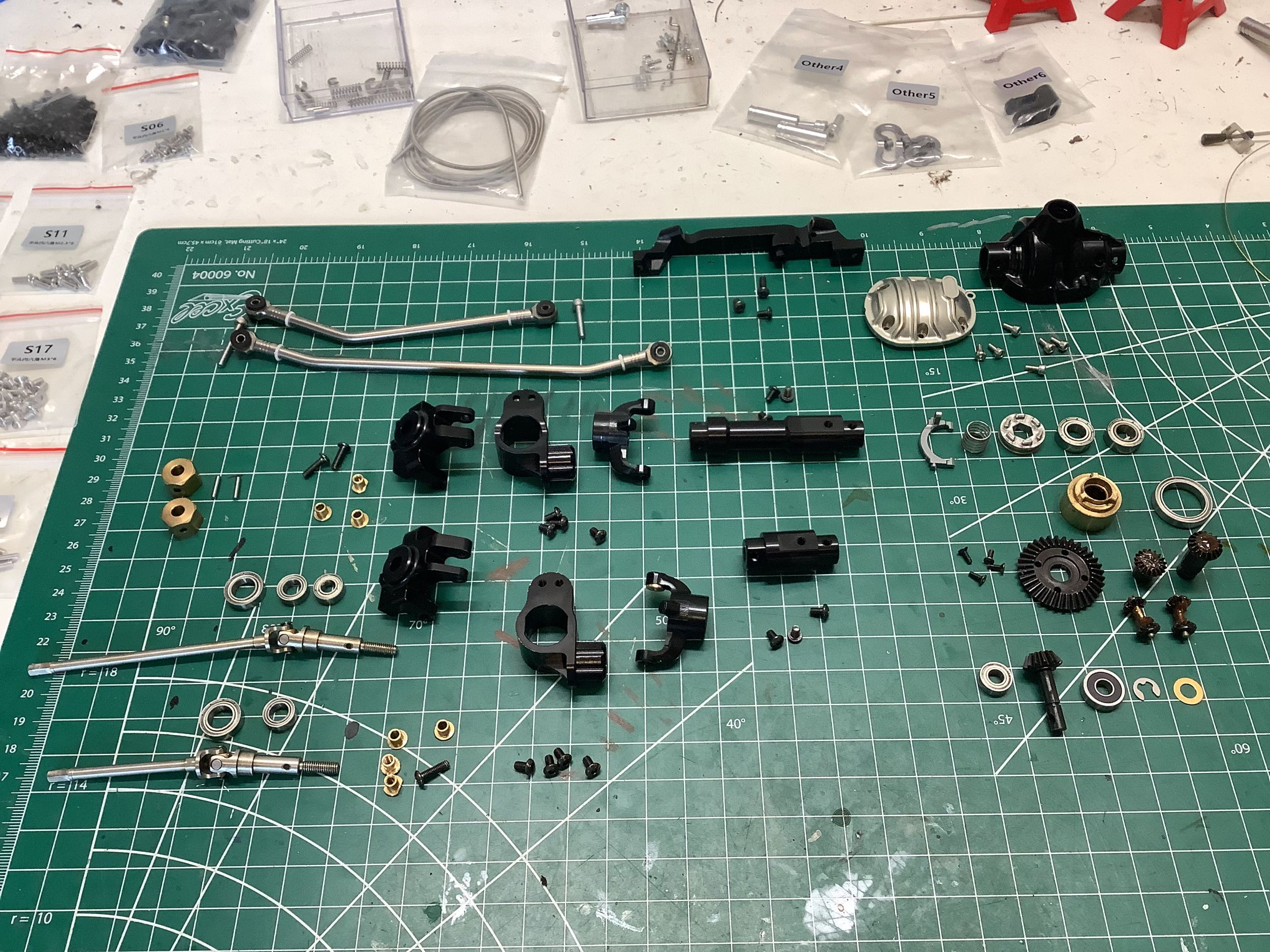
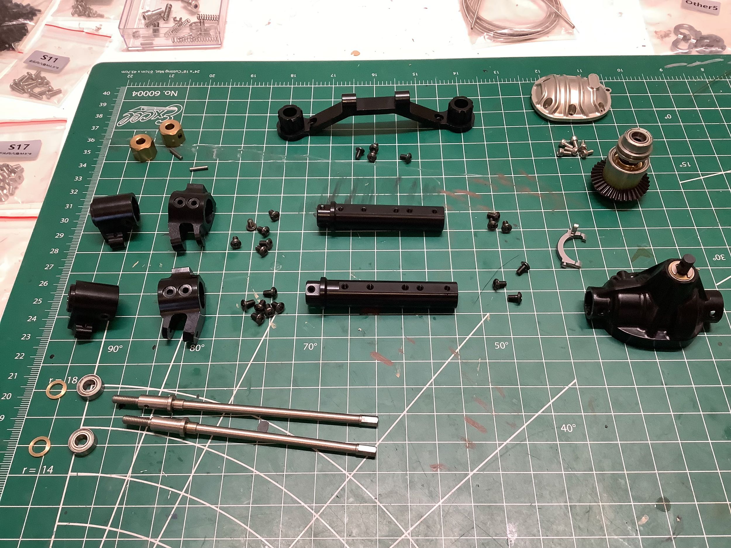
Here is the complete set of parts from a dis-assembled front axle
(left); at least 84 parts not counting sub parts of the universal joints
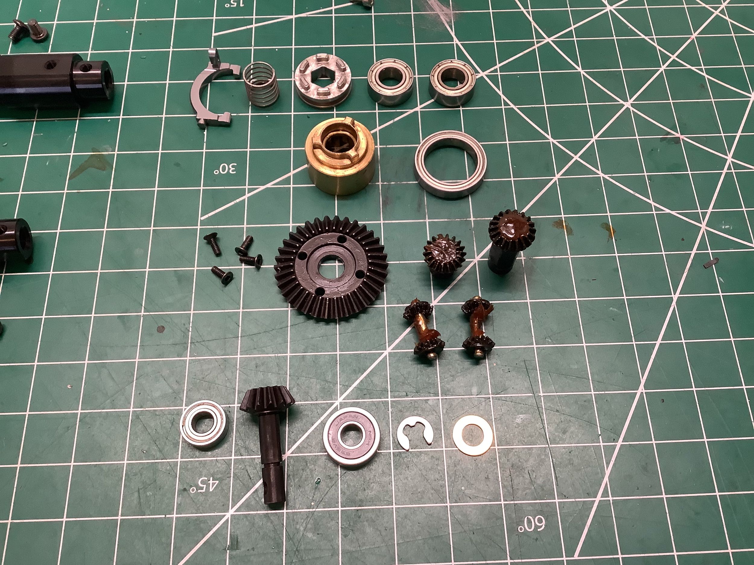
or tie rods. On the right you can see the parts for the locking
differential assembly, 5 of which are large bearings. The brass
diff housing has the dogs which will mate with the steel driving ring to
lock the diff when engaged. There are 4 spider gears in the
differential which seem pretty small for the weight of this truck.
Here's hoping that they hold up to the stress. The ring gear has
34 teeth and the pinion has 14 teeth so the axle ratio is 34:14 = 2.43:1
for a final drive ratio of 37.5:1 in low gear. This is not
particularly low for a truck of this size, making it more of a trail
truck than a rock crawler.
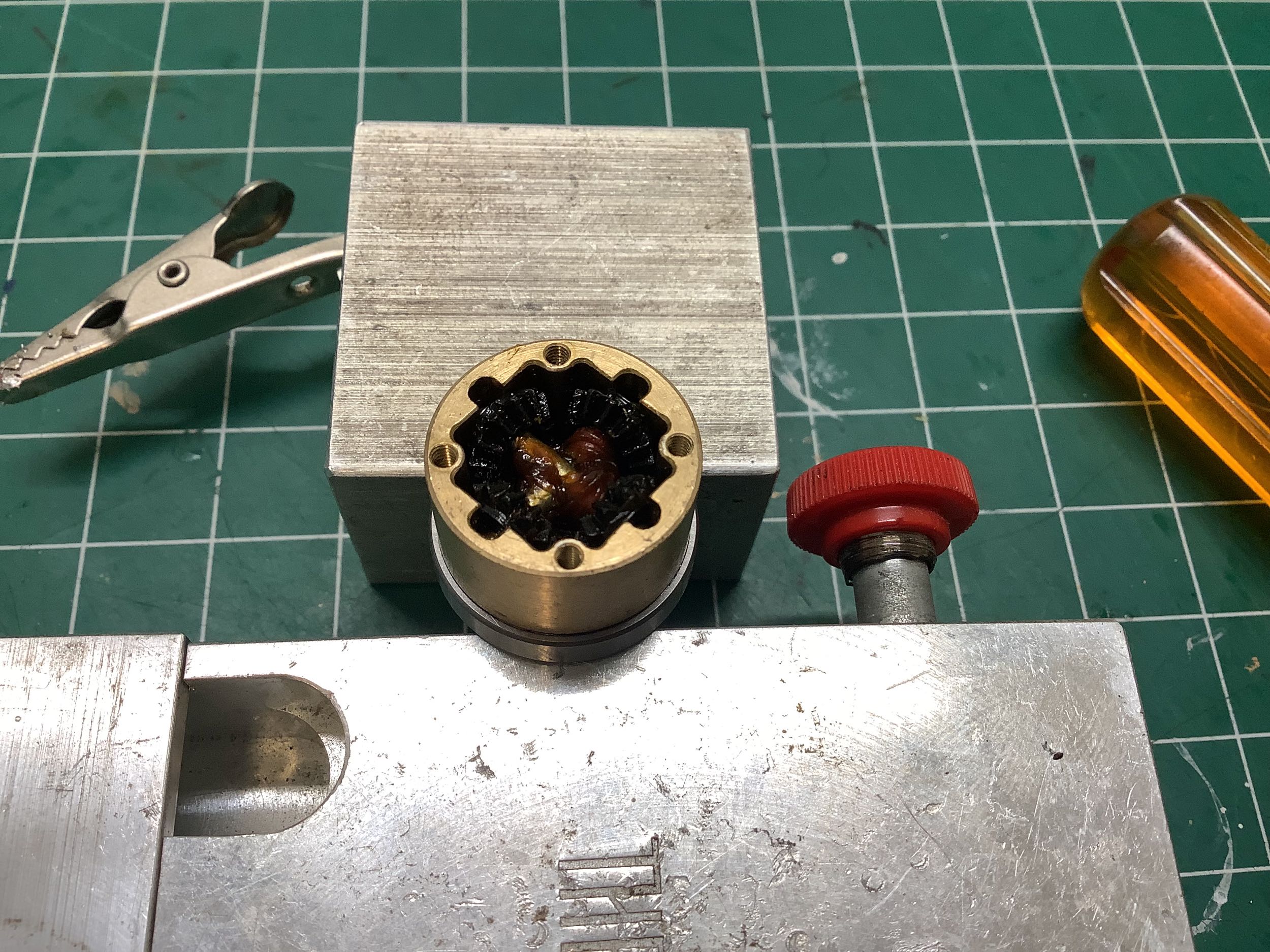
It's pretty dark down inside that differential housing so you can't see
much, but rest assured there's an output gear down there. The
picture on the right shows the spider gears installed. The grease
that you see was present already from the factory so I didn't need to
add any here.
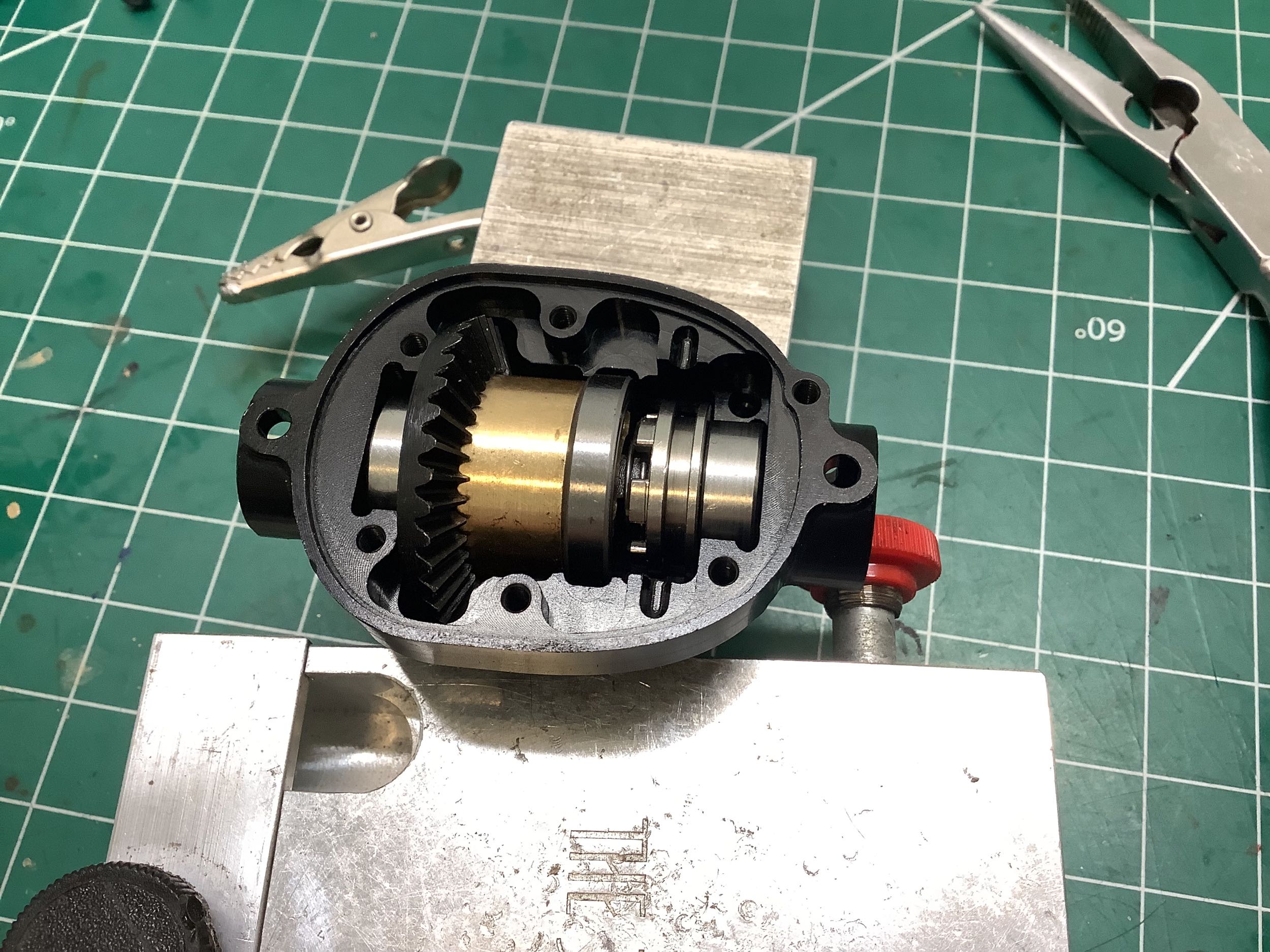
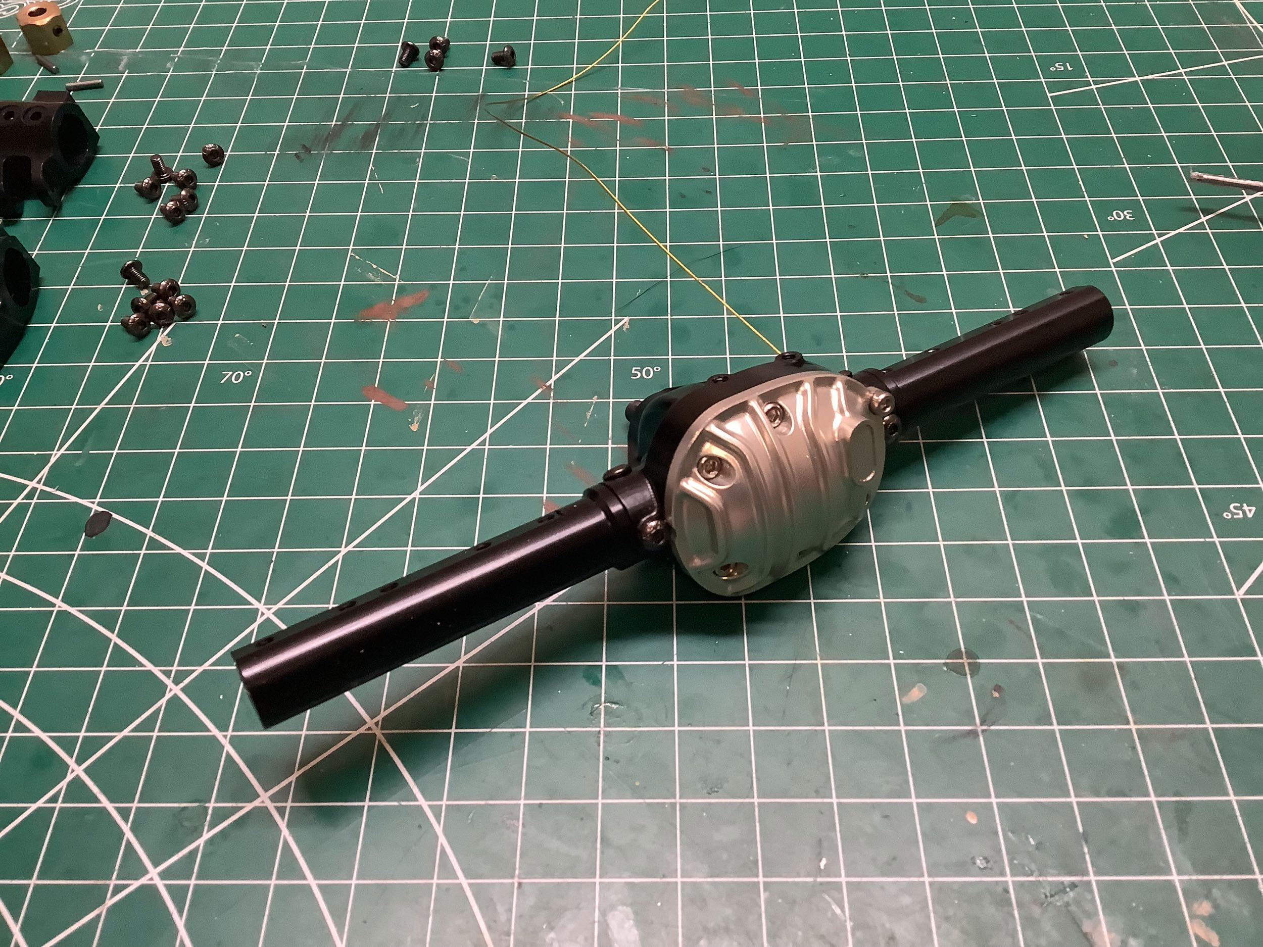
Here is the pinion gear installed into the housing, ready to accept the
differential. This is a very complex machined part, but not very
precise as we're about to discover.
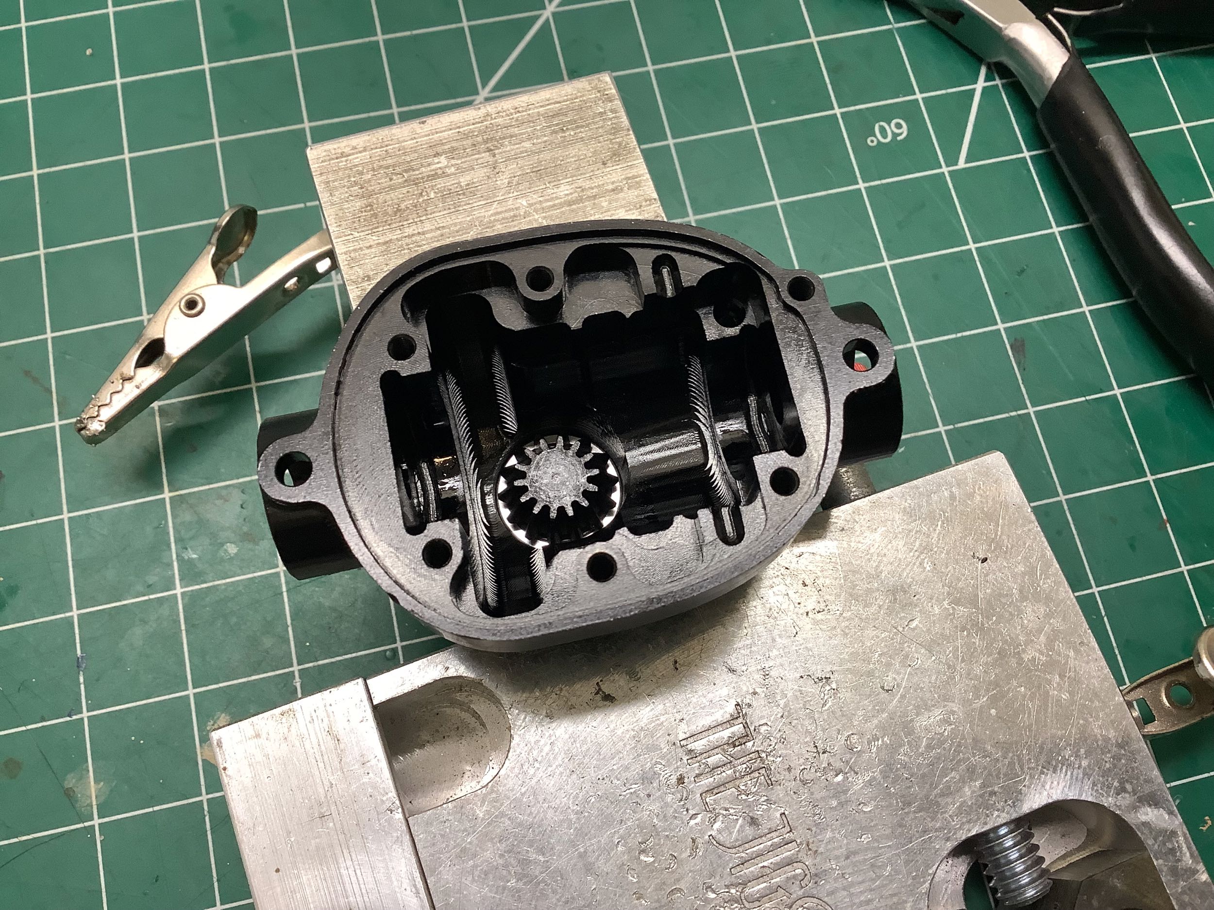
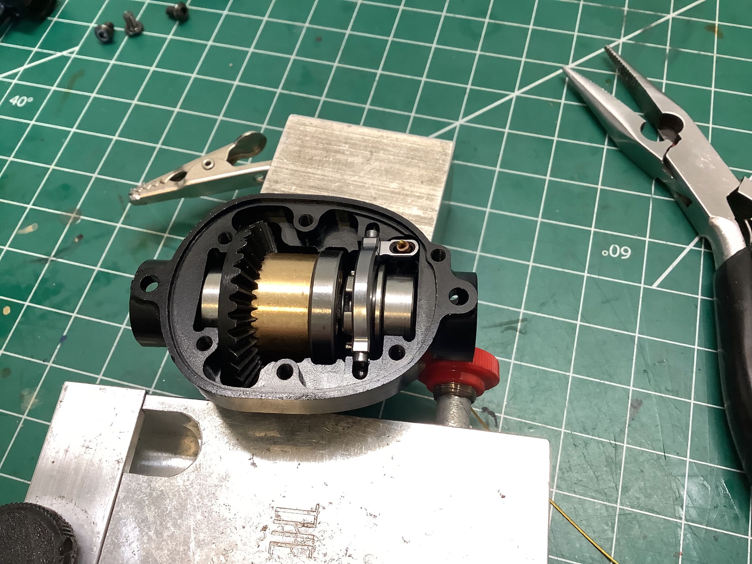
The picture on the left shows the differential assembly dropped into the
housing. On the right hand of the assembly is the locking ring
which is preloaded away from the differential with a small compression
spring. In the right image you can see the locking fork
installed. The upper right of the fork has a small horn with a
cable installed (facing away from the screen). When the cable is
pulled, the the crank rotates the fork and forces the locking ring to
the left, compressing the spring. The locking ring is keyed to the
right hand axle, so when it engages with the differential housing it
prevents relative motion and effectively locks the diff. In
theory.
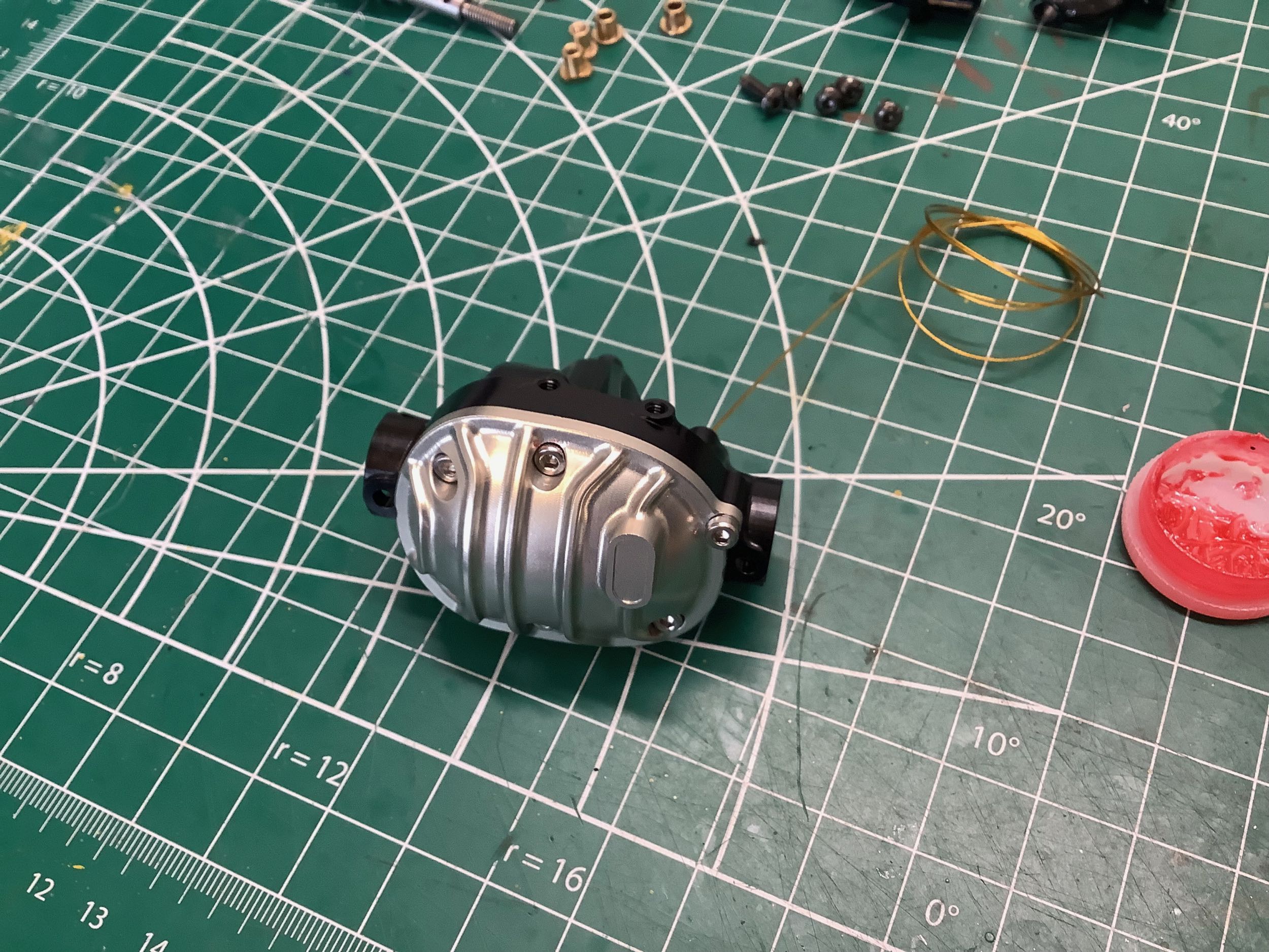
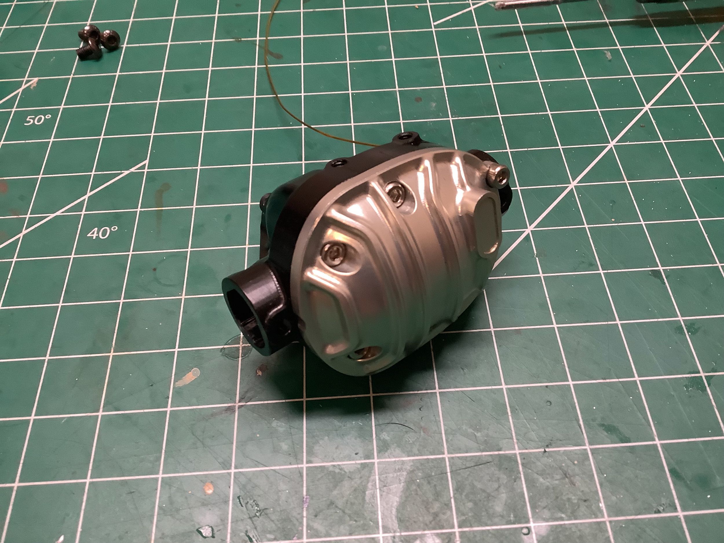
I added the differential cover and figured I better try out that cable
actuated diff lock. Nothing. The cable wouldn't move at
all. I tried the still assembled rear axle and found exactly the
same problem. The diff locking mechanism was completely
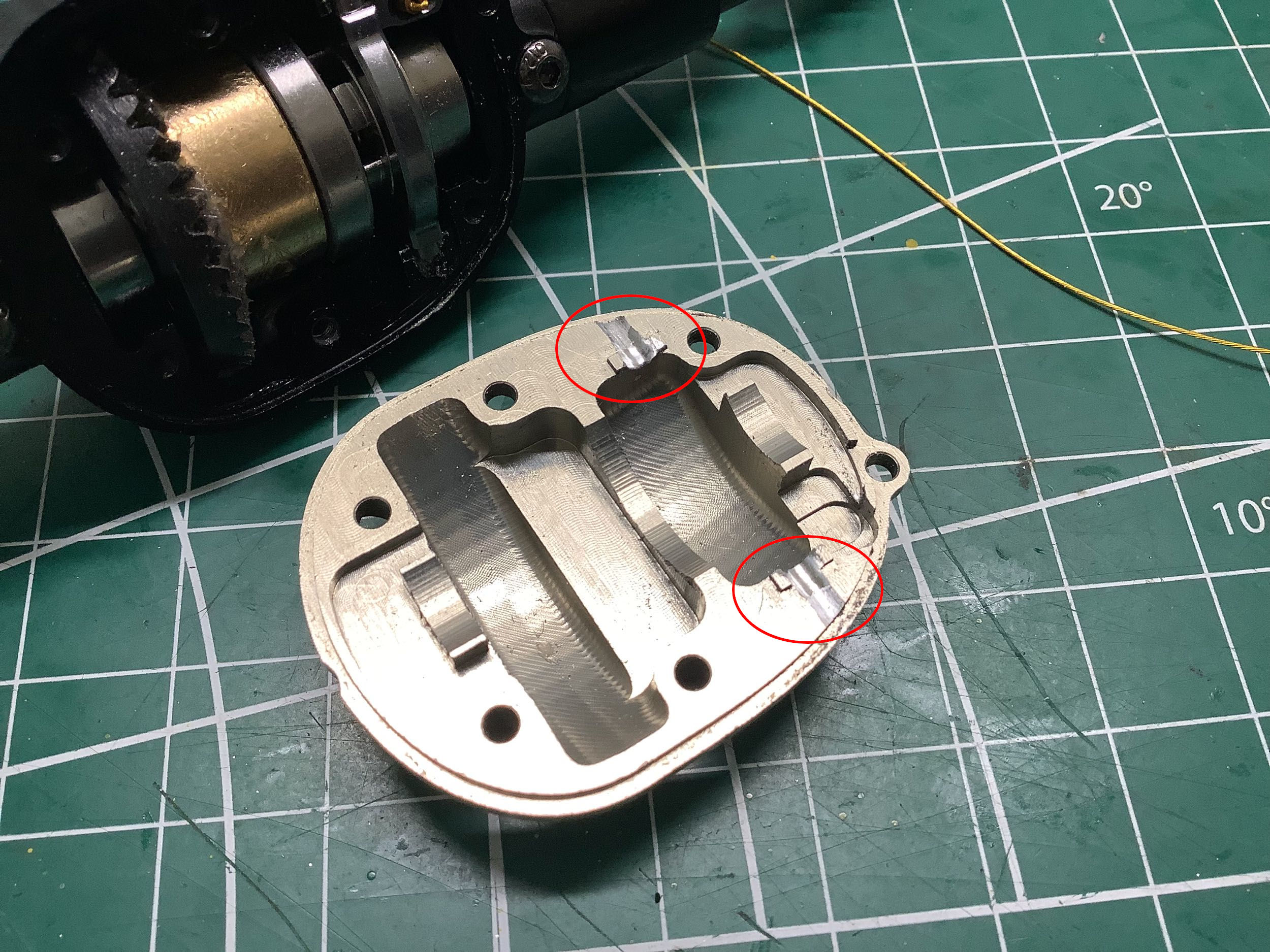
non-functional from the factory. I tried loosening all the bolts
on the diff cover and all of the sudden it worked fine. I could
now pull the cable and feel the spring compress, engaging the locking
function. The problem, as it turned out, was that the recesses machined
into both the diff housing and cover had too small a diameter which
resulted in a mild interference fit with the pins on the locking
fork. This meant that as soon as things were clamped up there was
no clearance for the fork to rotate. I had to use my Dremel to
manually grind away some of the material (circled at right). It
was an all afternoon affair trying to get it to work right without
mutilating the parts too badly, but it fixed the problem and will be
hidden once assembled. I could have also solved the problem by
reducing the diameter of the pins on the locking fork (which I tried),
but they were too small for me to effectively sand or grind, so opening
up the housings was the only option.
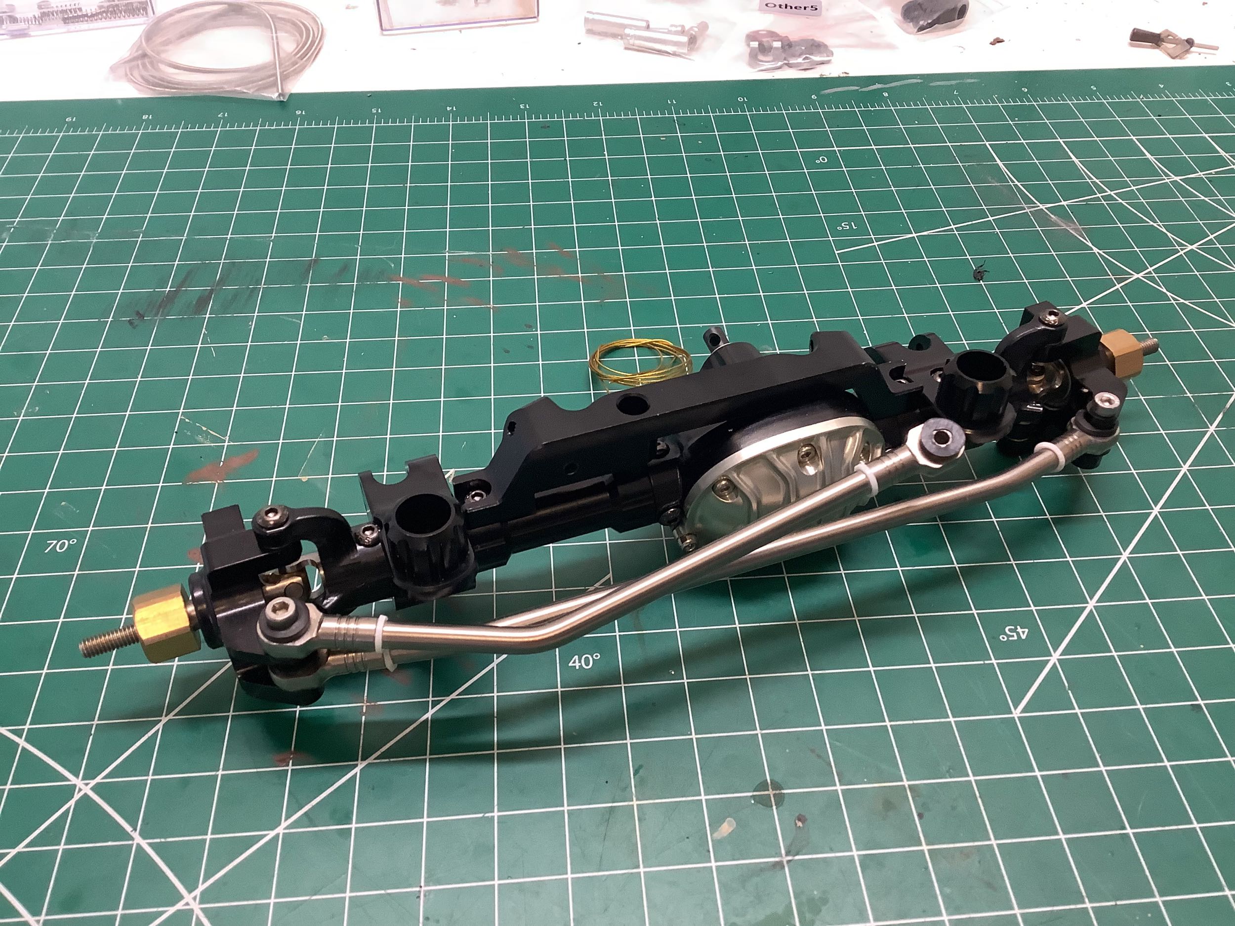
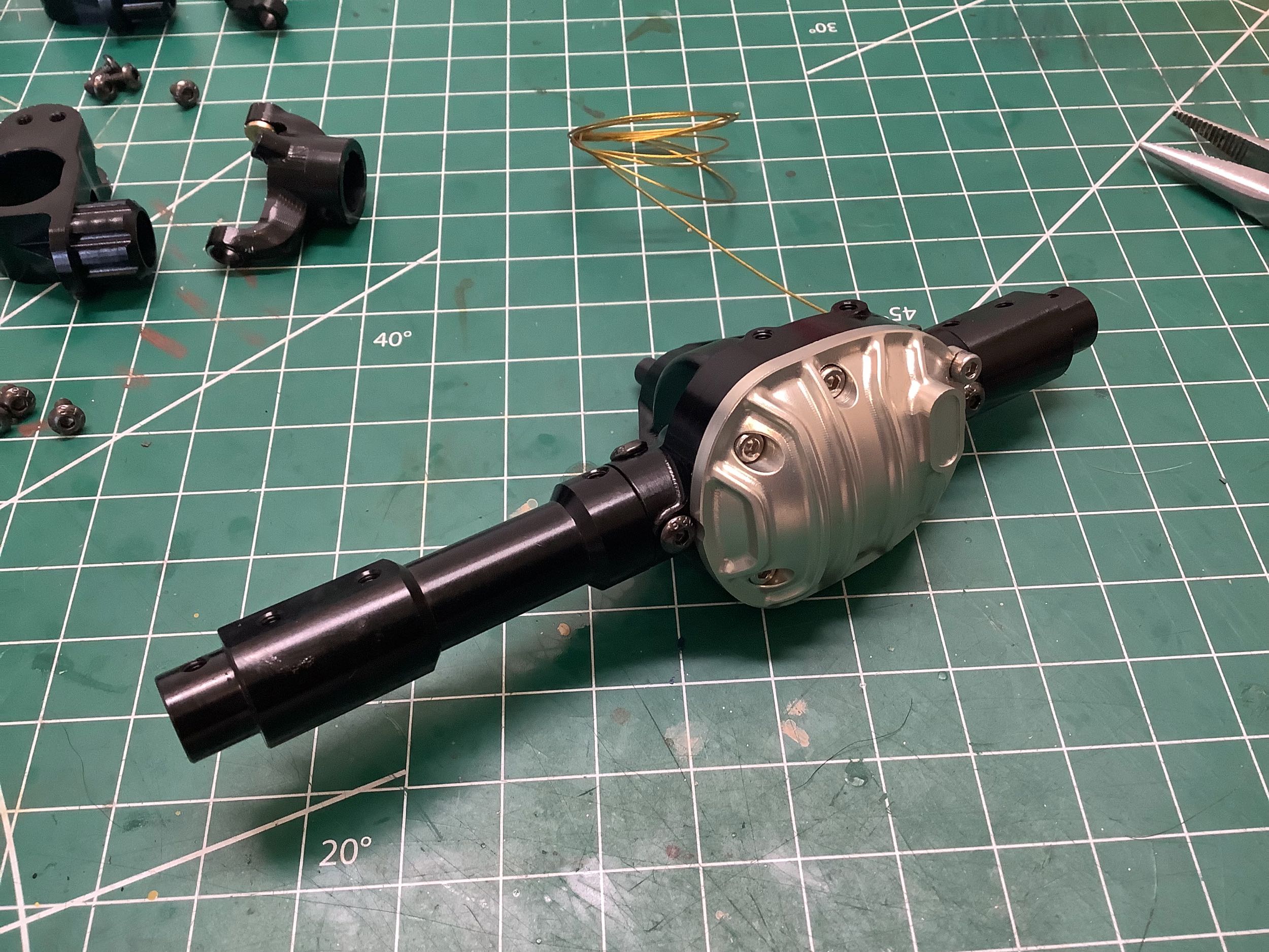
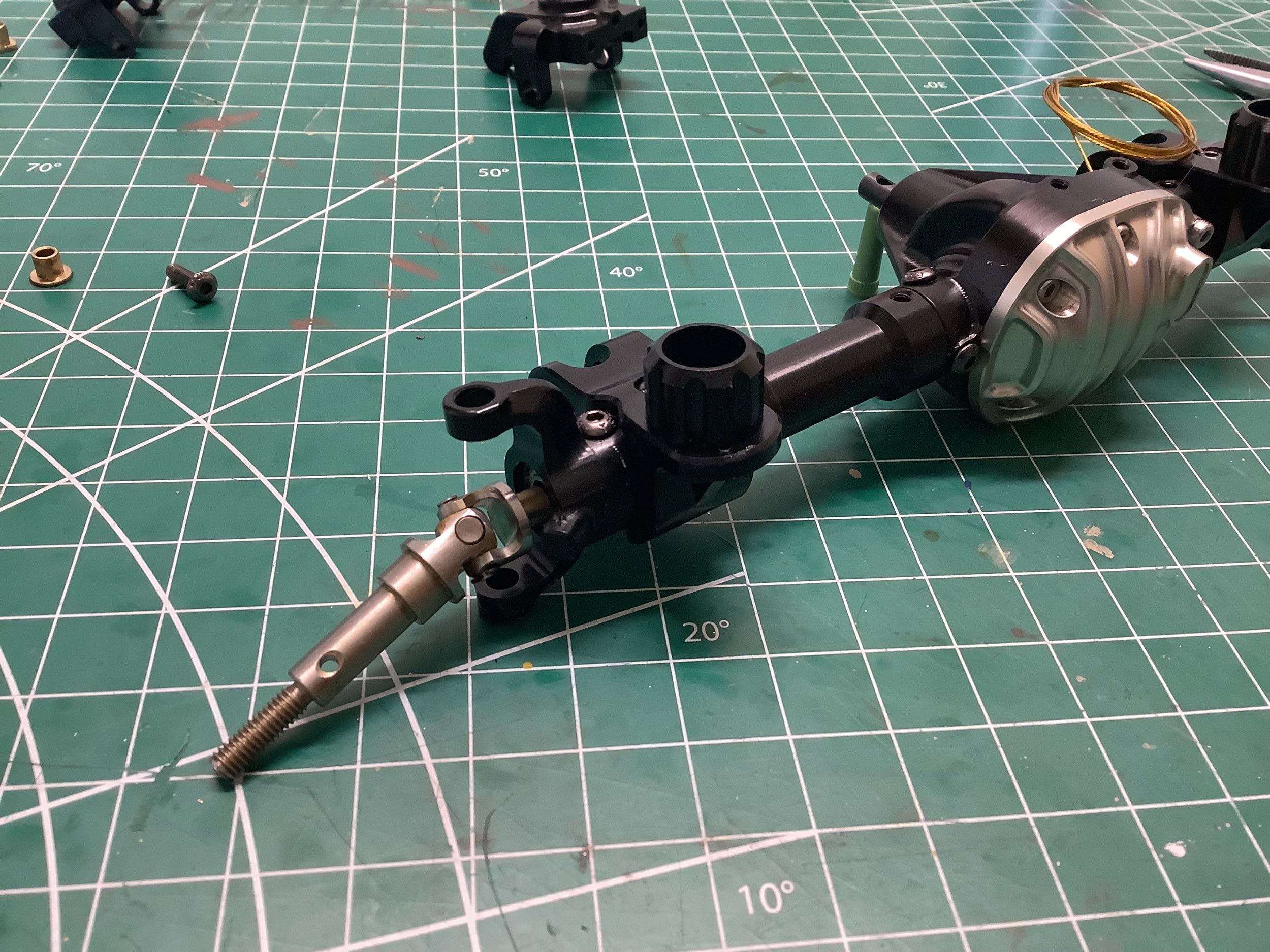
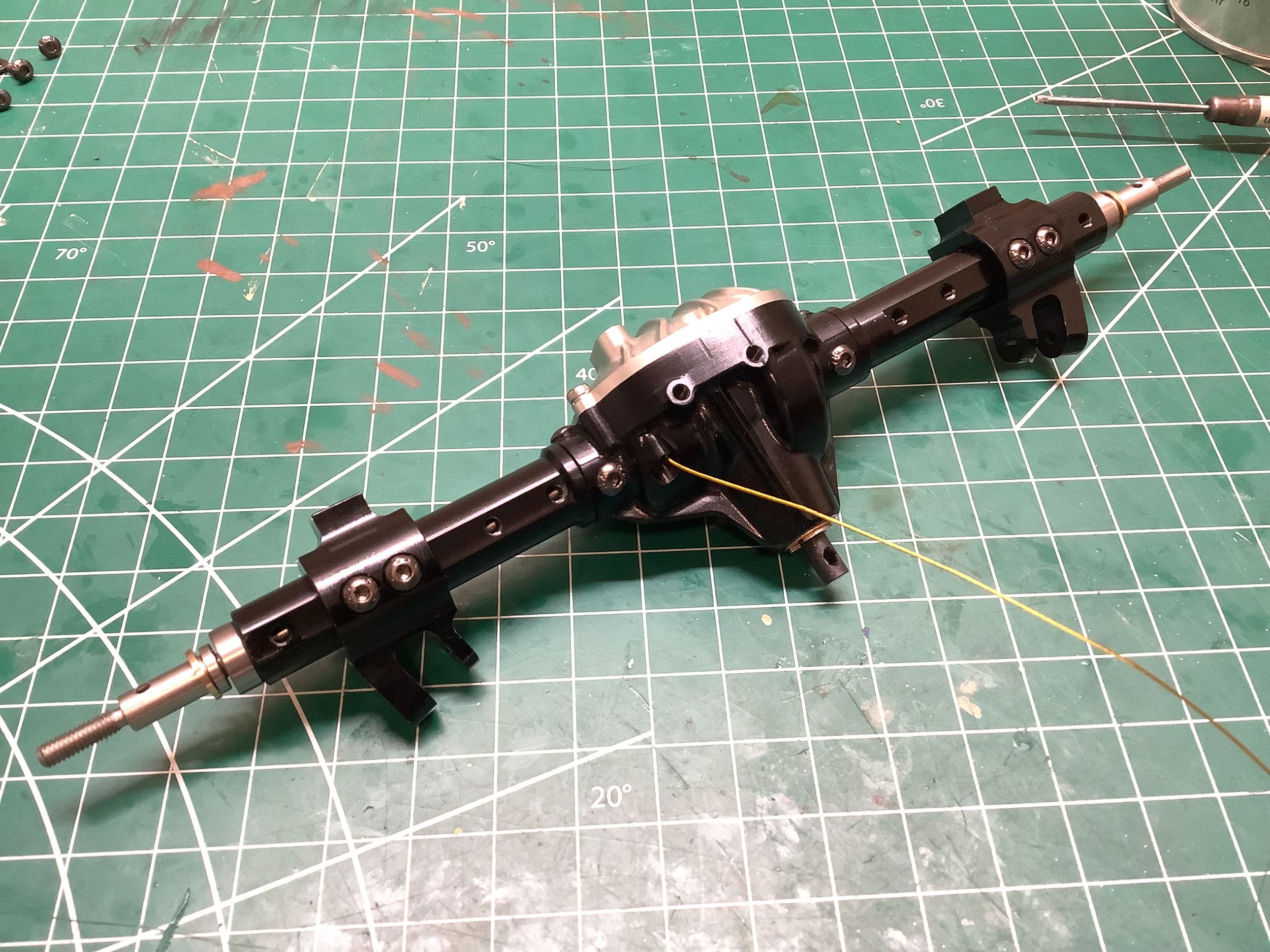
Now that the diff locker is working properly I can start the rest
of the axle assembly. On the left I've inserted the axle housings
which fit into triangular slots on the diff housing. Note that
they are vastly different lengths because the differential is off
center. On the right I've also added the spring perches and lower
link mounts.
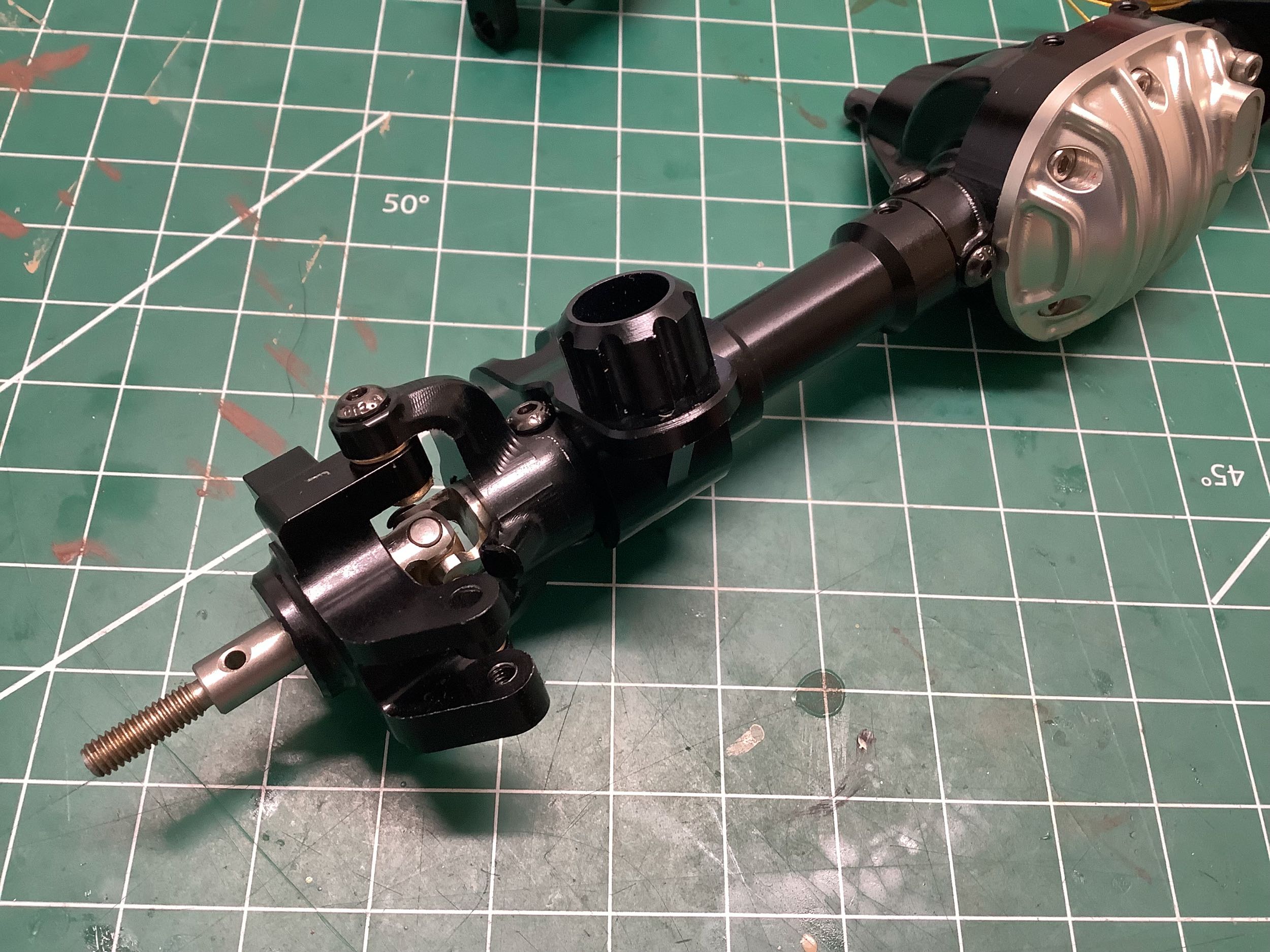
Now I've inserted the axles which have integrated universal
joints. You can see that the C-hub has no kingpin
inclination. On the right I've added the steering knuckle which
required re-installation of that mangled bushing from earlier.
Looks fine and, more importantly, works fine.
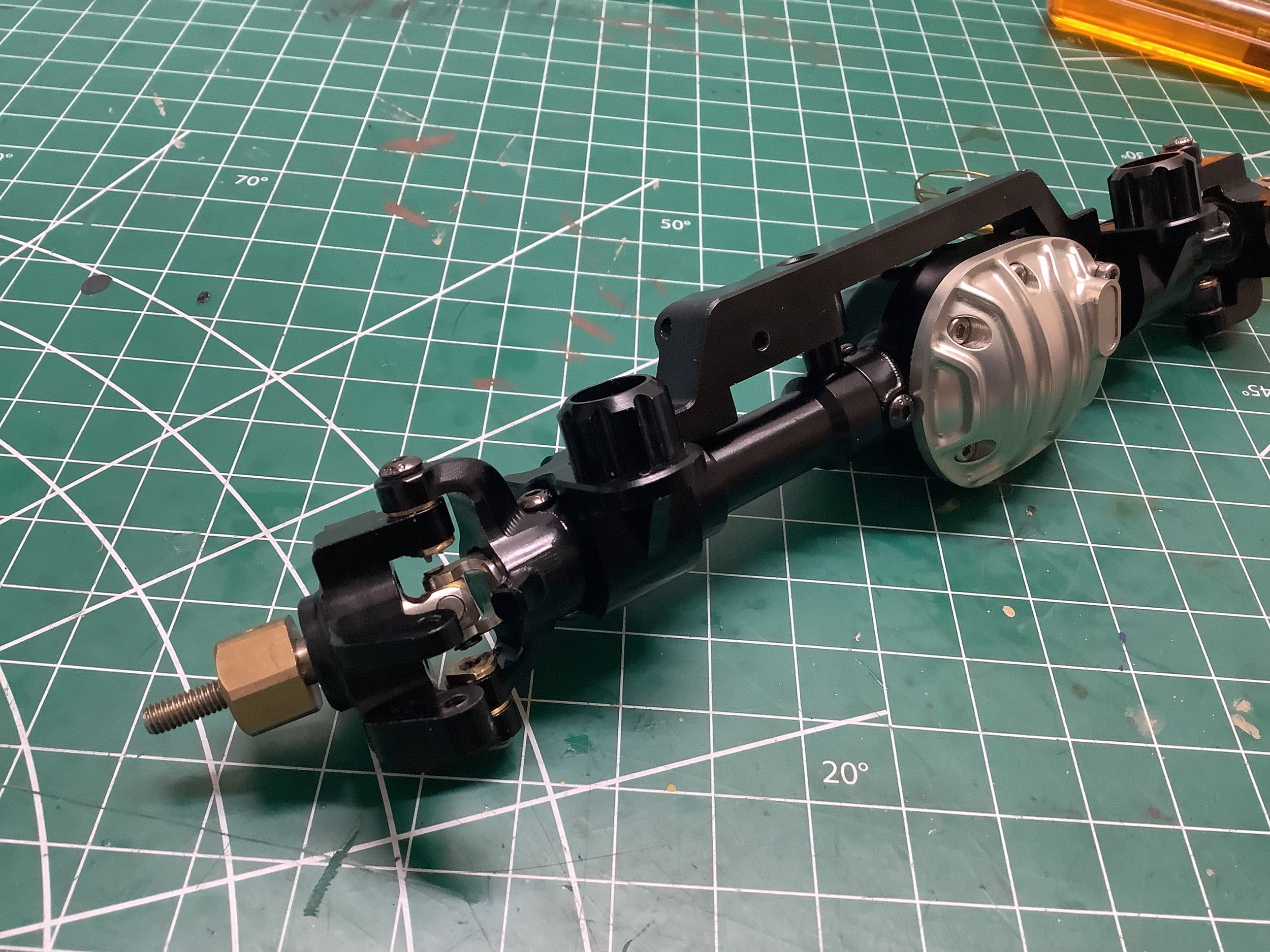
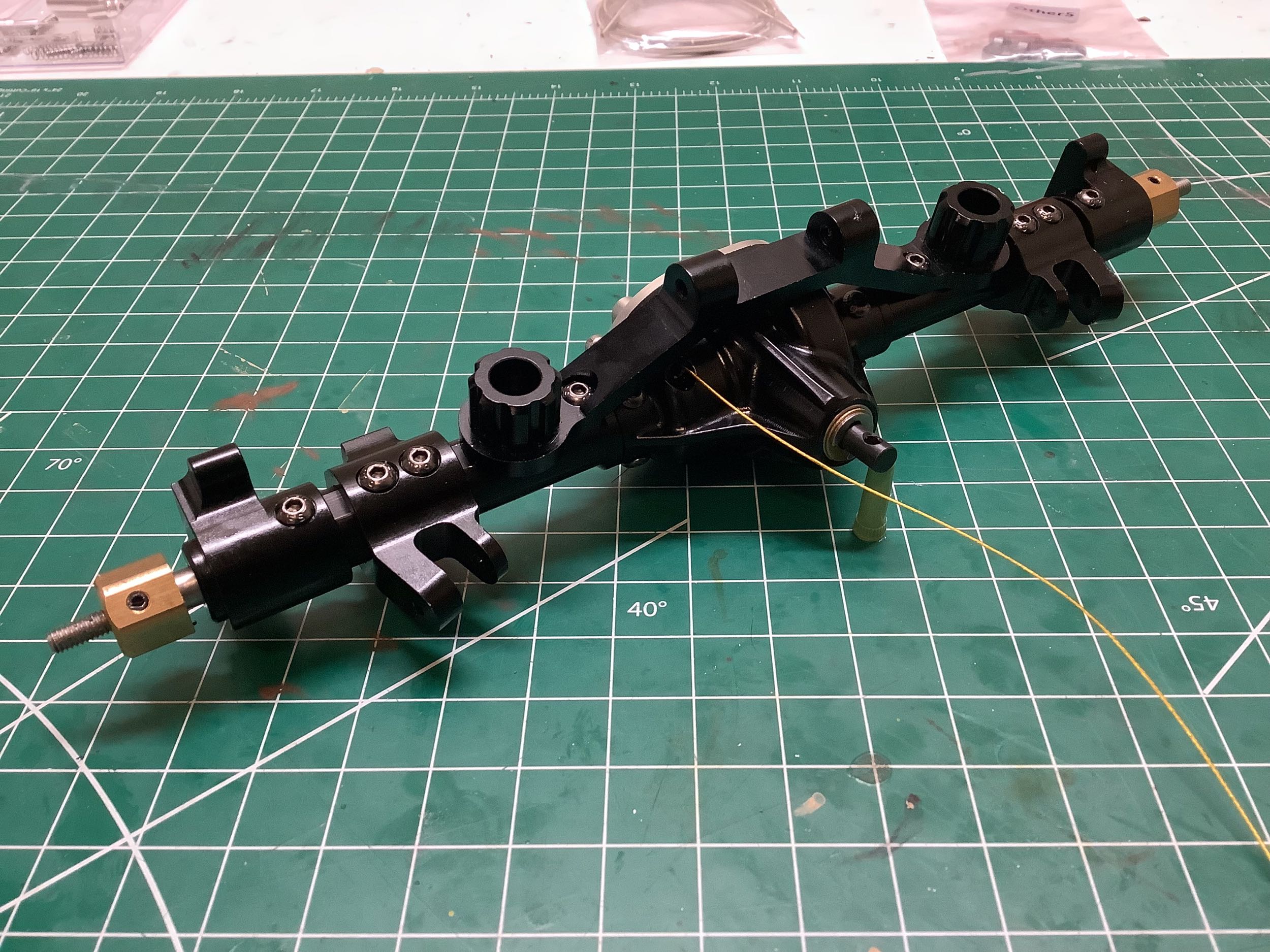
Here I've installed the stiffening truss which incorporates the upper
link mounts. On the right I've also added the steering link and
drag link in front of the axle. This would normally result
in reverse Ackerman geometry, but this model correctly locates the
steering link attachments outboard of the kingpins which
compensates. Good job again!
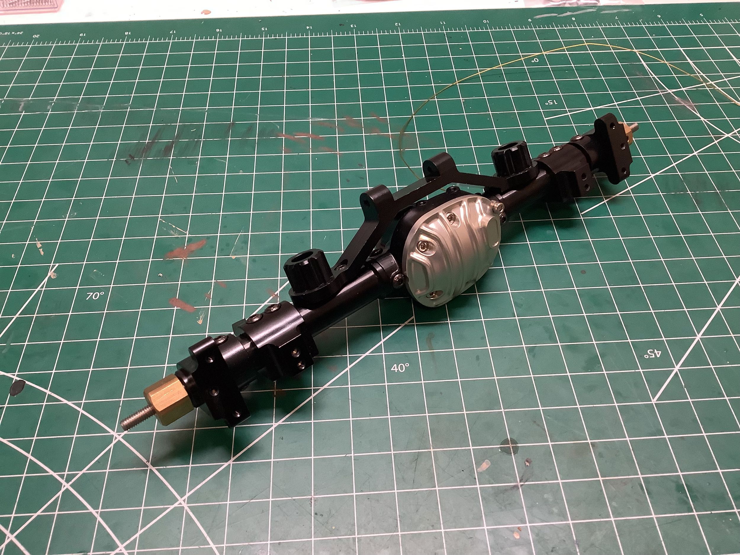
Done. Now let's compare the assembly as it came out of the box
(left) to my rebuild (right). Do you see the difference?
Neither did I. It wasn't until a month later when I powered it up
for the first time that I realized the front and rear wheels were
rotating in opposite directions meaning one or the other of the
differentials was installed upside down. It was the front.
It is hard to even see in these images, but pay attention to where the
cable comes out of the differential and you can see that it moved to the
other side of the pinion after my rebuild. It took me quite a
while to fix this.
I had originally planned to only rebuild the front axle since the rear
axle would be pretty much the same thing, but after the problems I found
I assumed modifications would be needed in the rear as well. I
was right. Oddly, even though the front differential was nicely
greased, the rear differential ended up being completely dry
inside. I added some grease and put it back together.
The rear locking mechanism required exactly the same grinding procedure
as the front to get it to operate smoothly. After that was done I
started adding the axle tubes. This differential is not as
obviously off center as the front, but the tubes are still slightly
different length so I had to pay attention to get it right.
Unlike the front axle, the rear axle uses separate parts for the
spring perches and lower link mounts. The springs are quite a bit
further inboard here. On the right I've also added the truss,
completing the rear axle assembly.
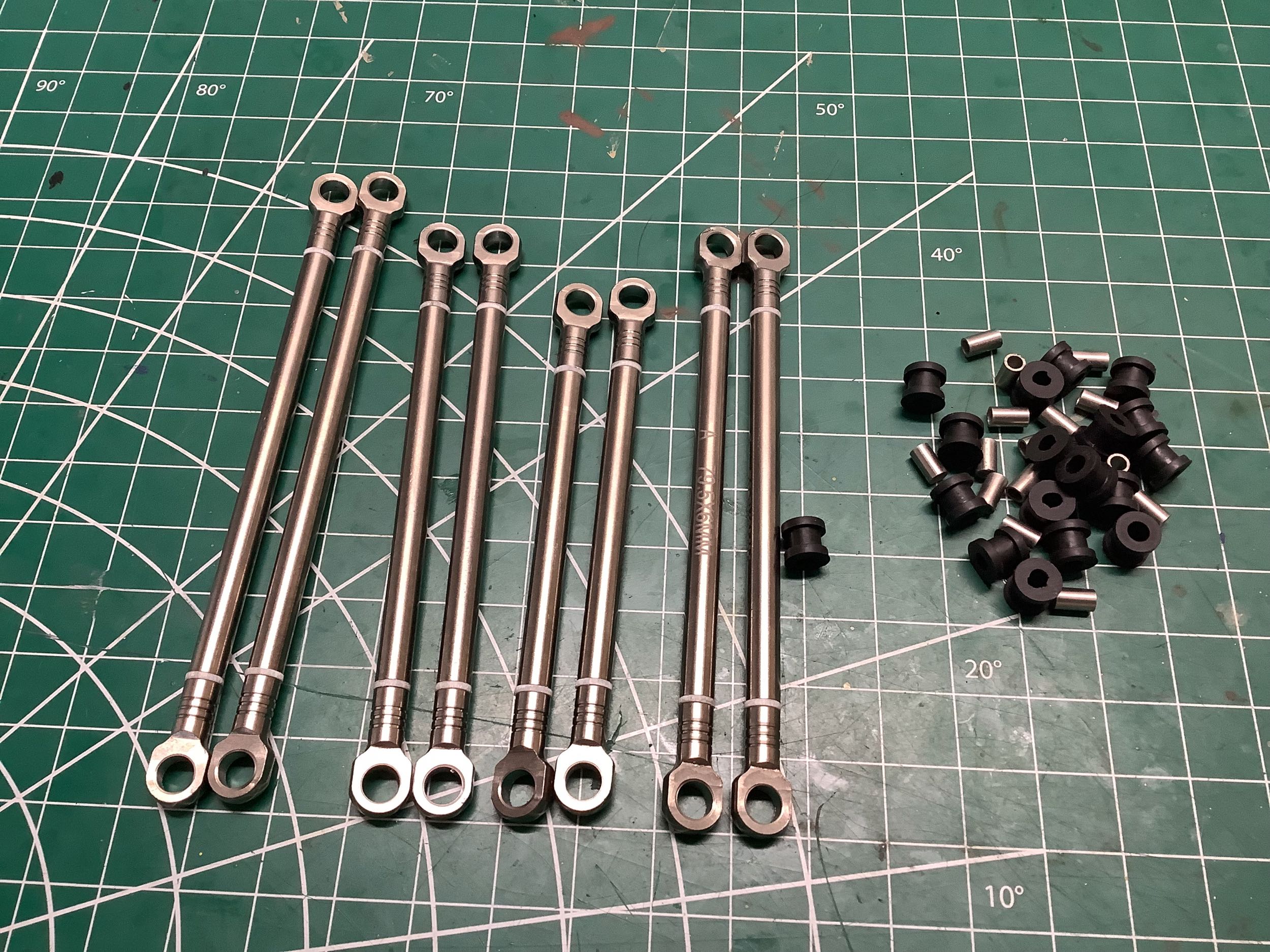
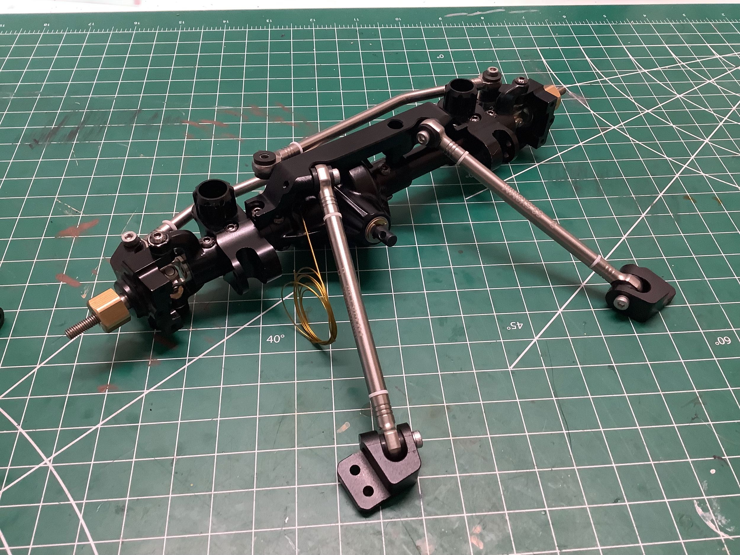
Here are the suspension links which appear to be titanium.
Interestingly, the kit came with a full package of plastic rod ends and
metal balls, but none of them are used by default. These metal rod
ends use rubber inserts and straight spacers instead. Without the
ball joints these rod ends have less rotational capability than the
plastic parts would, but it seems to be enough for full suspension
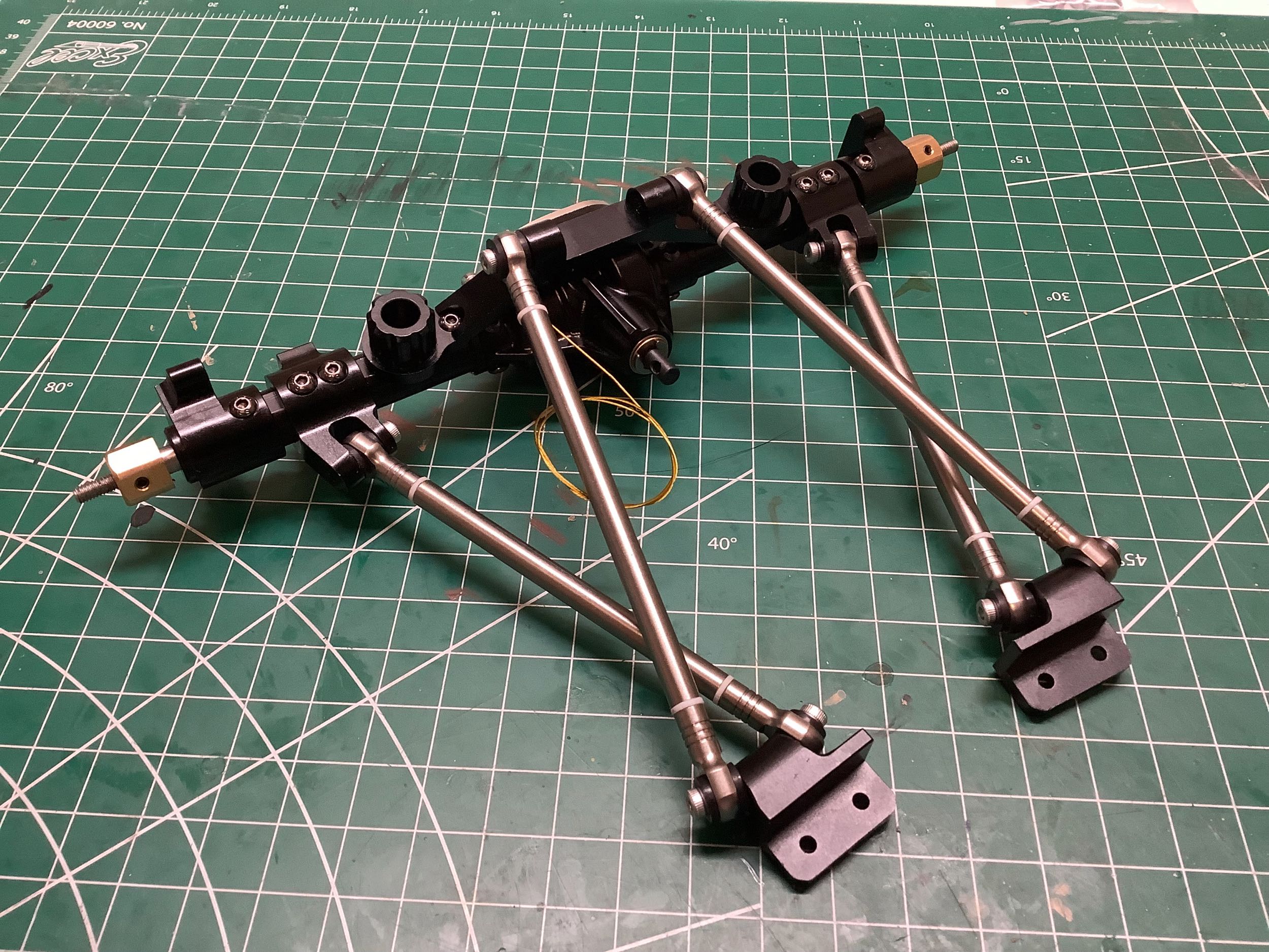
articulation. On the right I've installed the upper links on the
front axle as well as the brackets that will attach them to the
chassis. They are well triangulated.
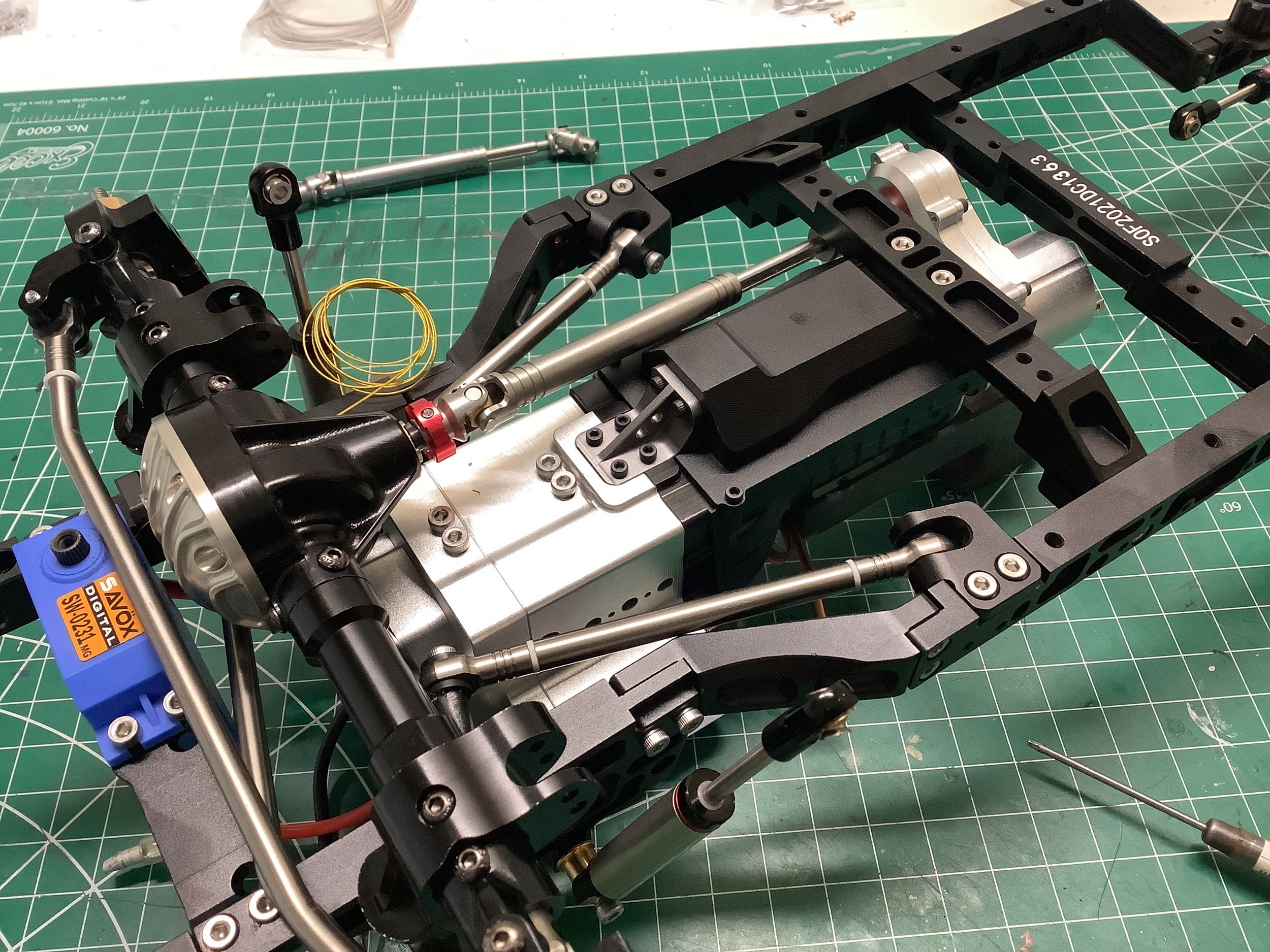
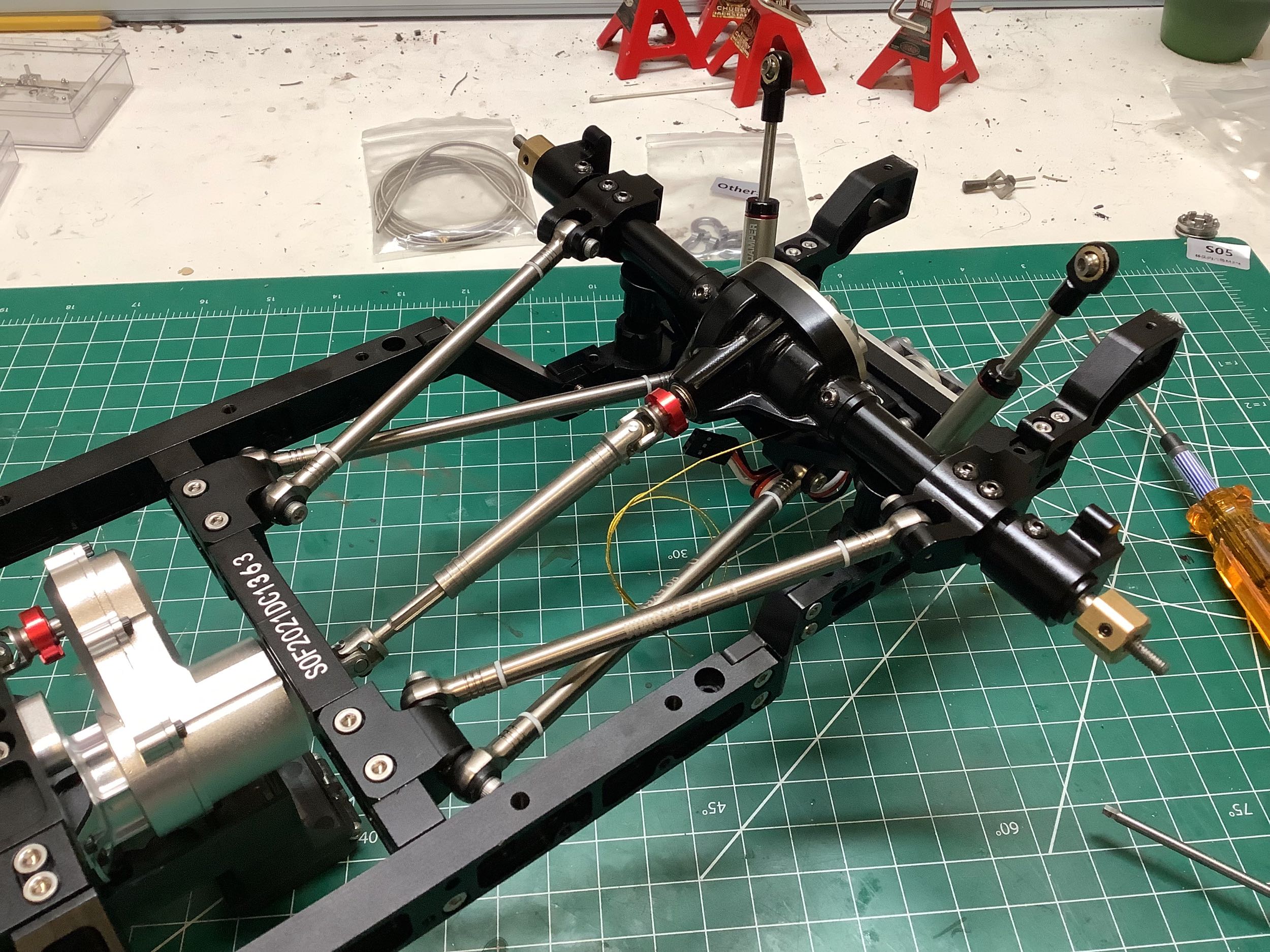
Now the front axle can be installed onto the chassis. We start by
sliding the drive shaft halves together and then bolt the upper link
brackets to the frame. On the right I've added the brackets for
the lower links which connect to a frame cross member. The upper
links end up having almost no triangulation. Ideally there would
have been a panhard bar to help with lateral motion.
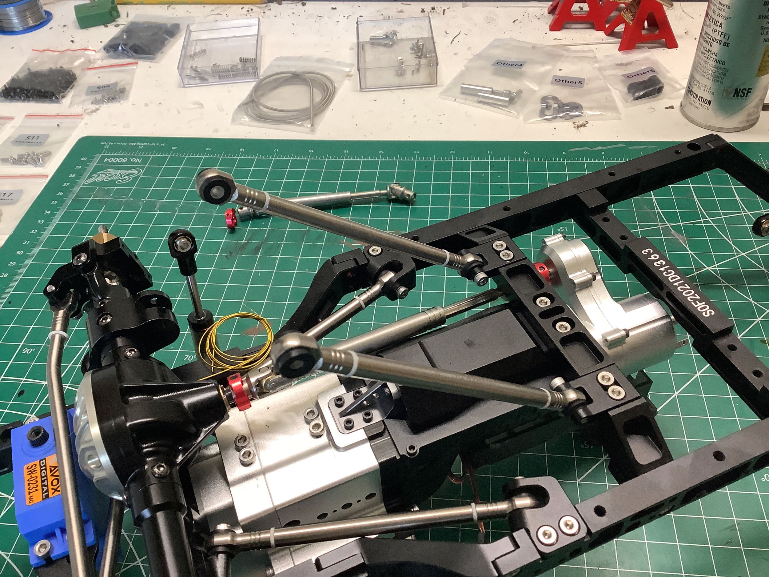
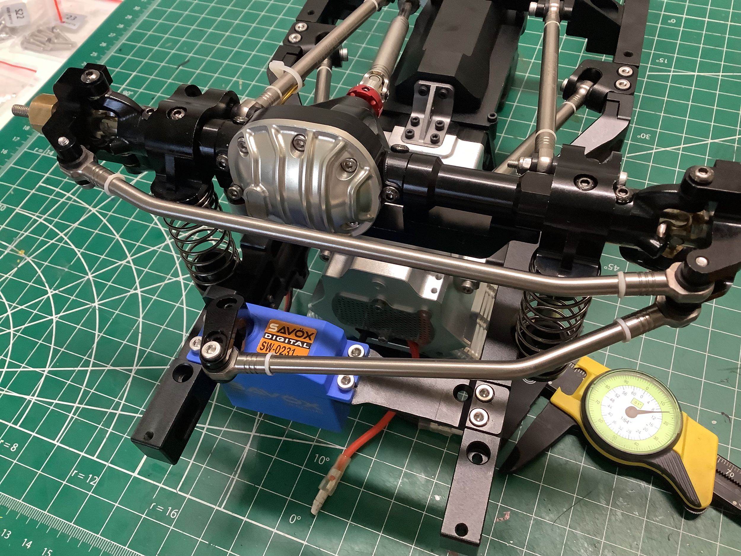
This vehicle does not use coilover shocks. The damper and spring
are totally separate components with different mounting locations as
shown on the left. I really like this arrangement. On the
right I've connected the drag link to the steering servo. Note
that the instruction video shows a clamping servo horn with multiple
holes which is different than what actually comes in the kit. It
is still a nice metal horn though.
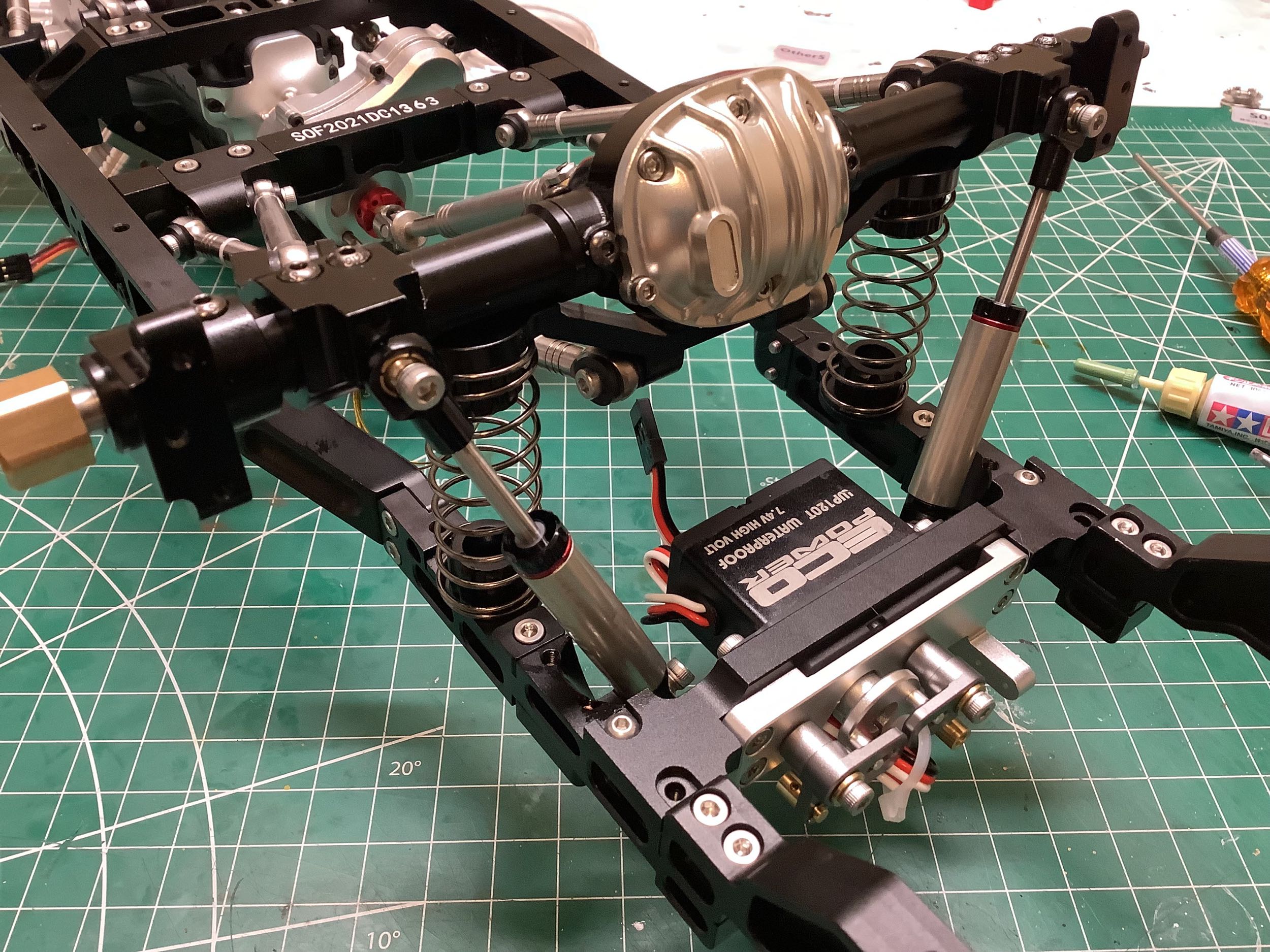
The rear links connect quite differently. Both the upper and lower
links connect to the same bracket and actually cross over each
other. This results in considerable triangulation for all
links. The installed rear axle is shown on the right. The
link brackets attach to the rear frame cross member.
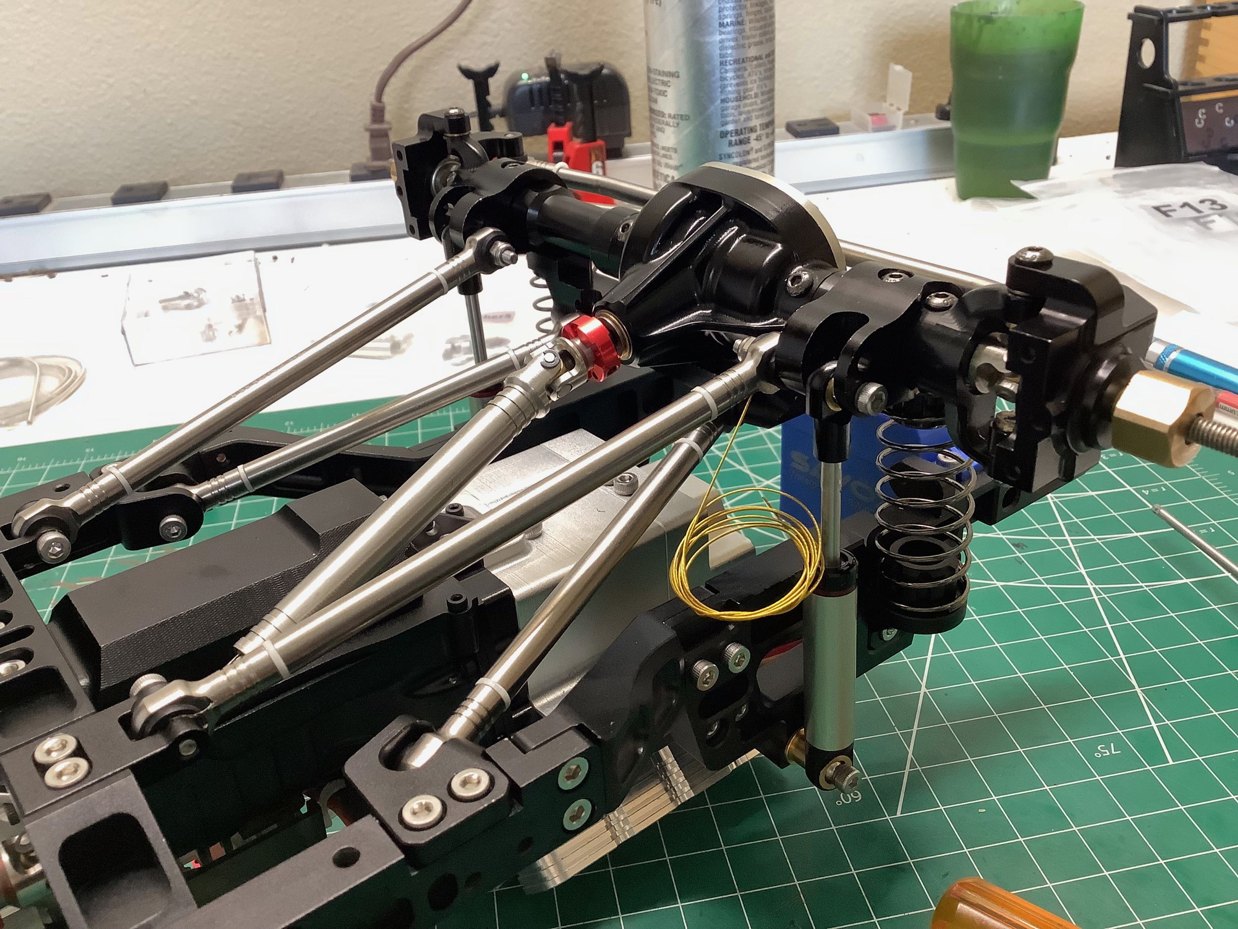
Finally, the rear springs and shocks can be attached to complete the
installation of the rear axle and the entire chassis assembly.
At this stage of the build it was possible to make a rolling chassis and
actually try out the model with minimum functionality so I had to skip
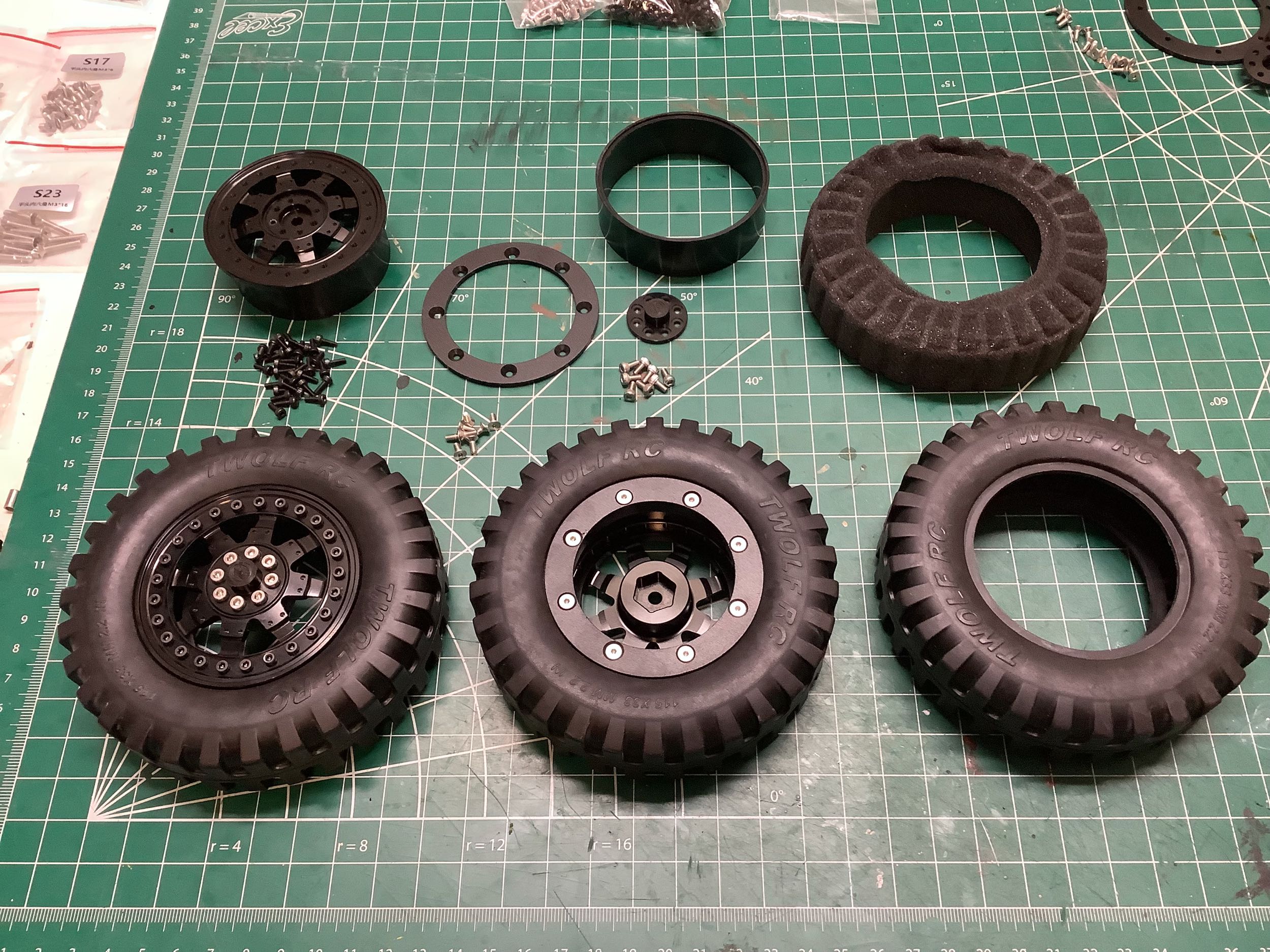
ahead and assemble the wheels (left). The metal beadlock wheels
use an inner spacing ring, a primary wheel part, and a locking
ring. There is also a hub to cover the wheel nut. The 8
countersunk silver screws you see on the back of the wheel are what
actually lock the bead. The 25 tiny cap screws around the
perimeter on the front are just for show. There are also 8 cap
screws to hold on the hub. The inner foam is quite stiff and is
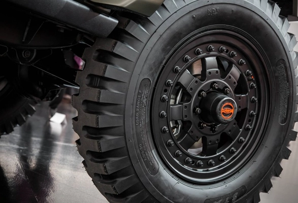
ribbed as shown. The tires are perfect scale examples of NDT
(non-directional tread) military tires used on the real truck
(right). These are 9.00-20 tires from STA (Specialty Tires of
America). This means they fit a 20" wheel and are 9" wide at the
tread. Tires of the early 1960's were generally made with a 90%
aspect ratio, but these are a bit taller with an overall diameter of
over 40". The model tires are a very good match.
©2022 Eric Albrecht