Tamiya Bruiser Project
Page 3: Finishing the Chassis
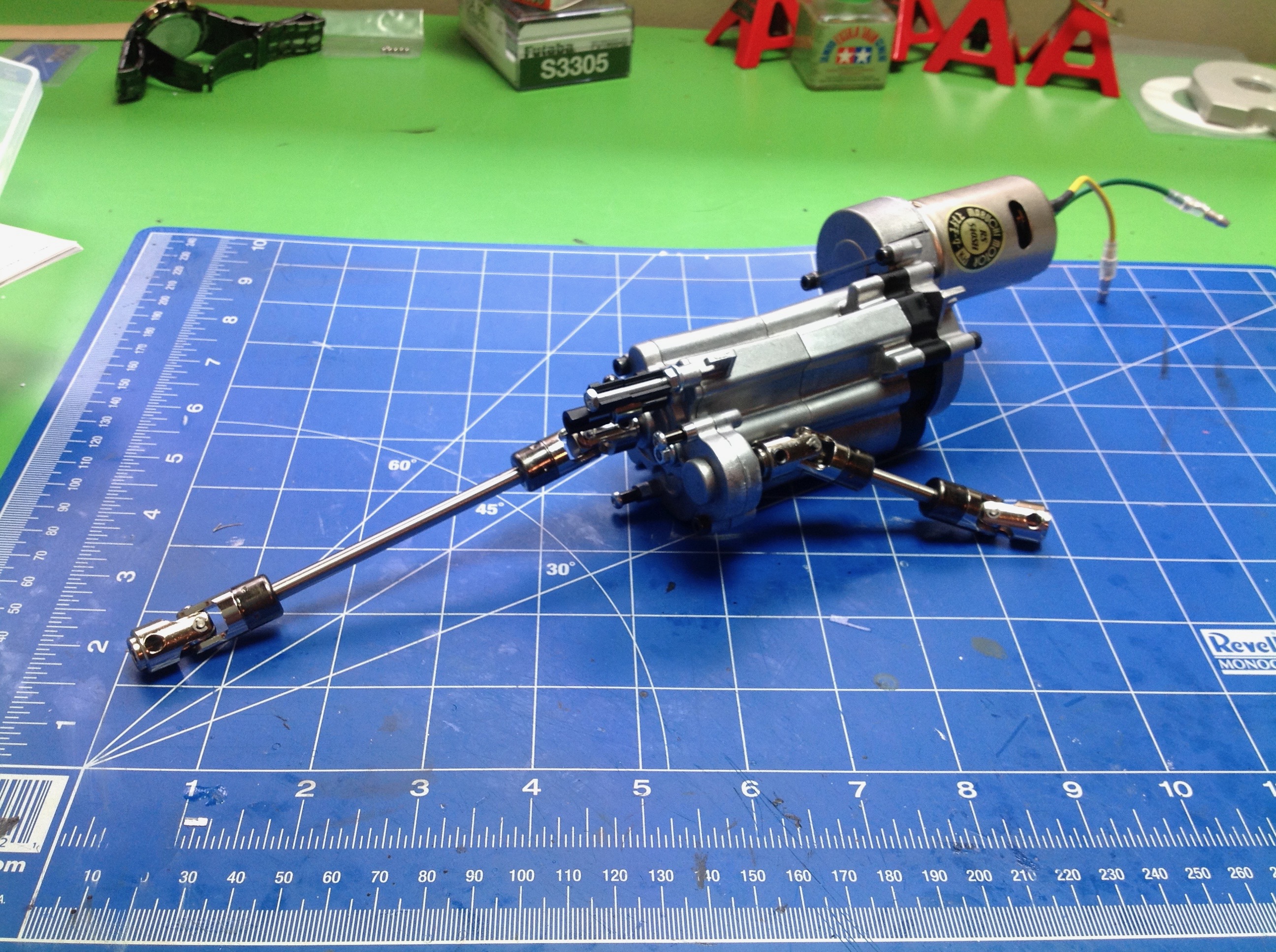
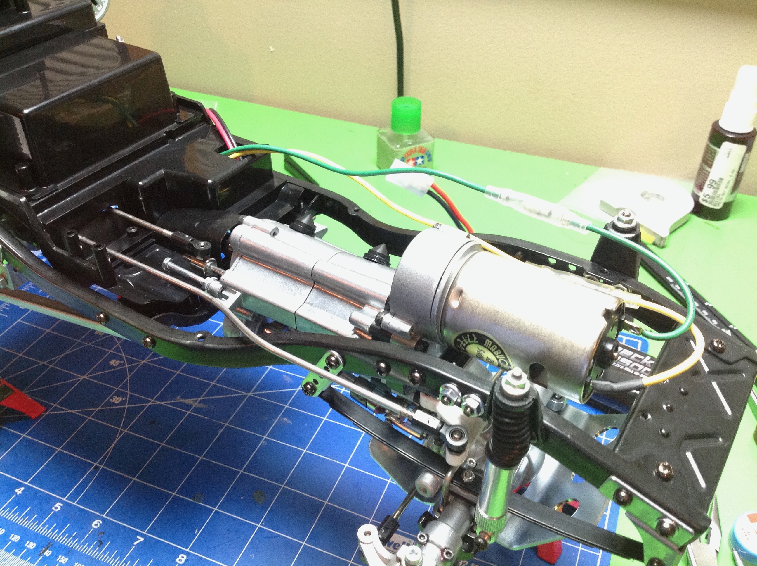
Step 25 installs the drive shafts onto the gearbox. The drive
shaft and u-joints are really nice steel units which allow a bit of
telescopic motion. The instructions tell you to put some CA glue
on the E-clips of the u-joints but I ignored this advice and paid the
price later when one fell off. Follow the instructions.
Step 26 installs the gearbox in the chassis. The mounting system
is very clever. The whole assembly just slips into a pair of
rubber grommets which act as vibration isolators. This makes it
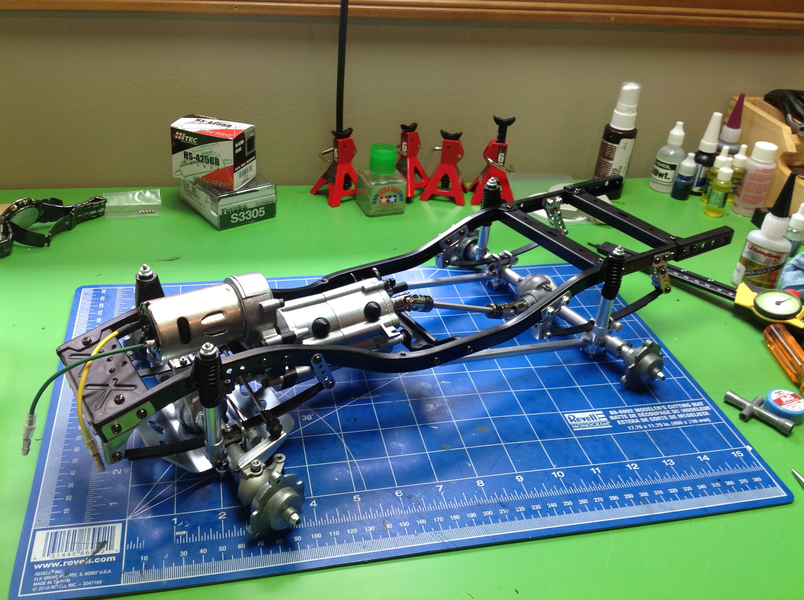
fairly easy to remove. At this point, nothing is stopping us from
hooking up the electronics and firing up the motor, so of course that's
what I did. At this point the transmission is locked in 2nd gear,
but you can actually drive around on the wheel hubs to try it out.
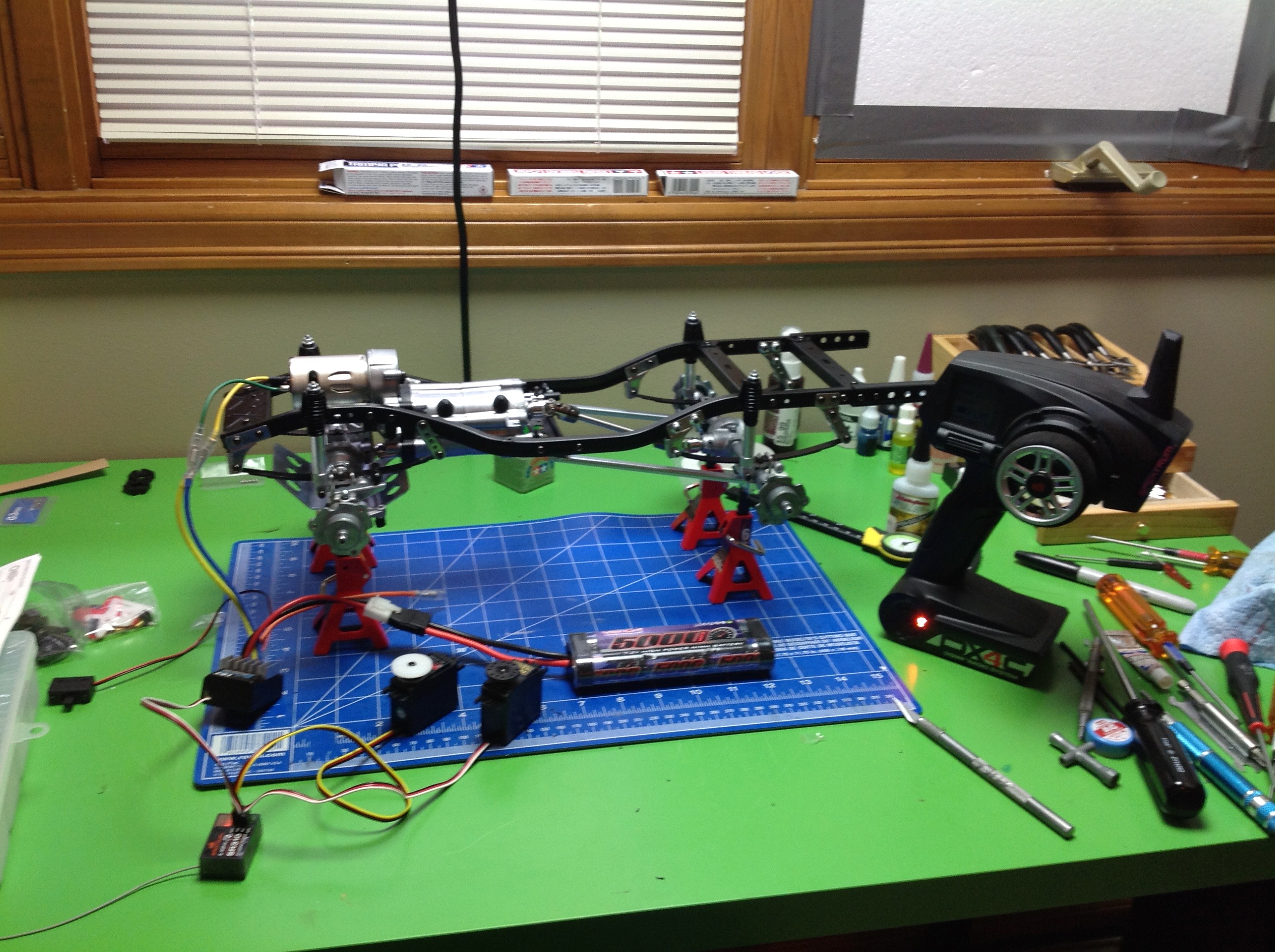
Steps 27 and 28 have you test wire the electronics. I started out
with a Tamiya TEU-105BK controller and a 5000mAh NiMH battery along with
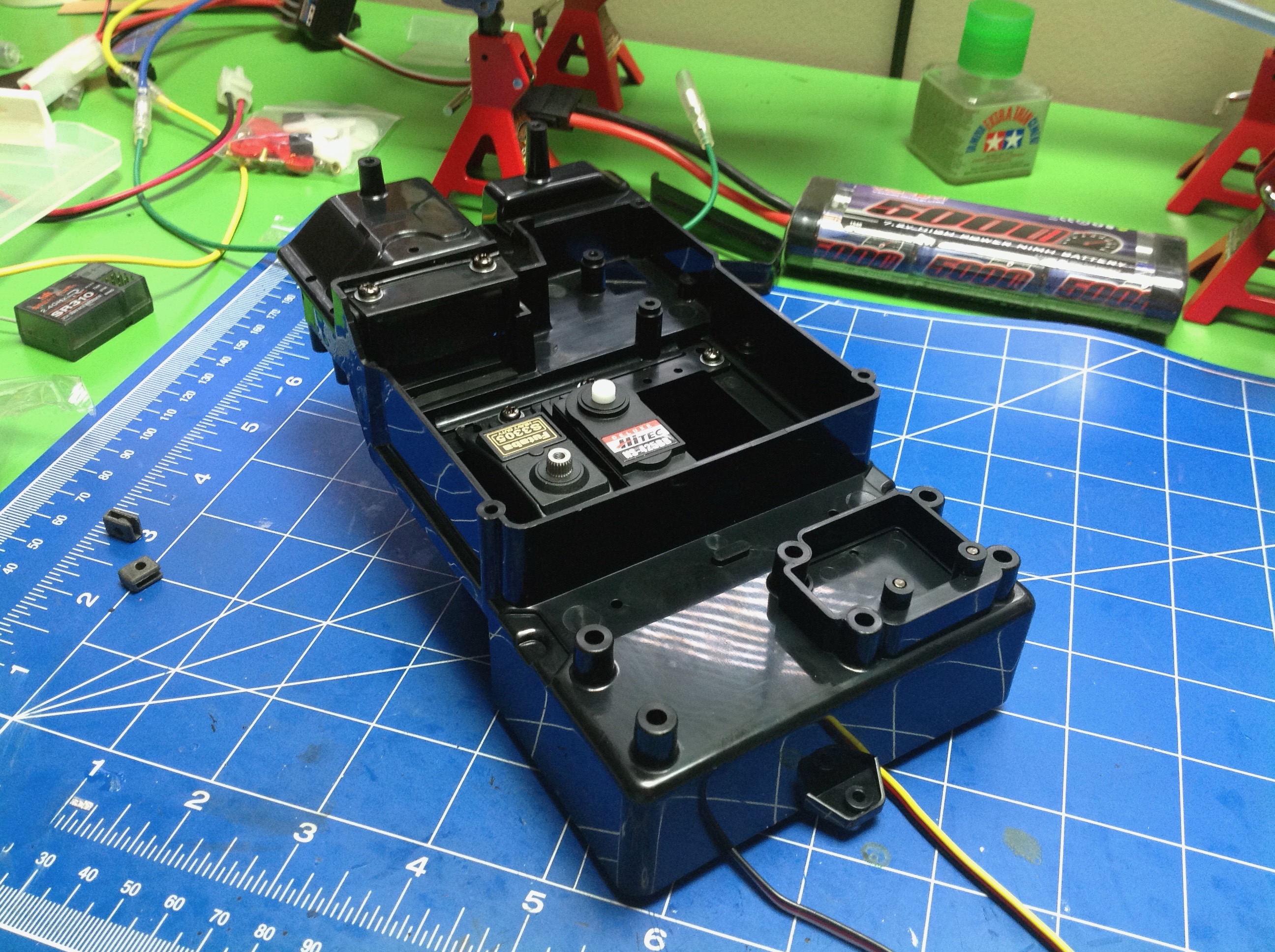
a Spektrum 3 channel receiver. Step 29 installs the servos into
the electronics box. I used a Futaba S3305 for steering because it
has good torque but a cheap HiTec HS-425BB was good enough for
shifting. The original would have had a 3rd throttle servo to
control the mechanical speed controller. The servos face downward
when installed on the
chassis. The electronics box does a reasonably good job of
protecting everything from contamination or water, but is not completely
sealed.
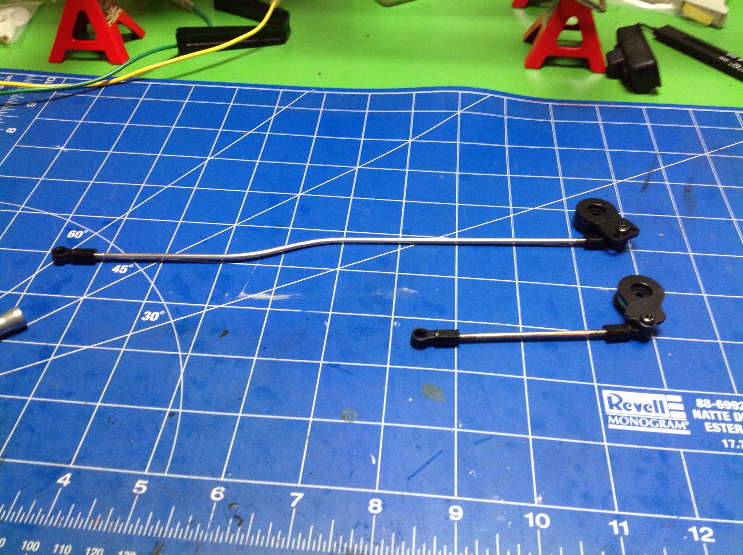
Because the electronics box is located on the back of the chassis, we
need long linkages to reach the steering and shifting balls. The
kit comes with two high torque servo savers which use metal
springs. The rods exit the electronics box through an opening
which is sealed with a rubber flap.
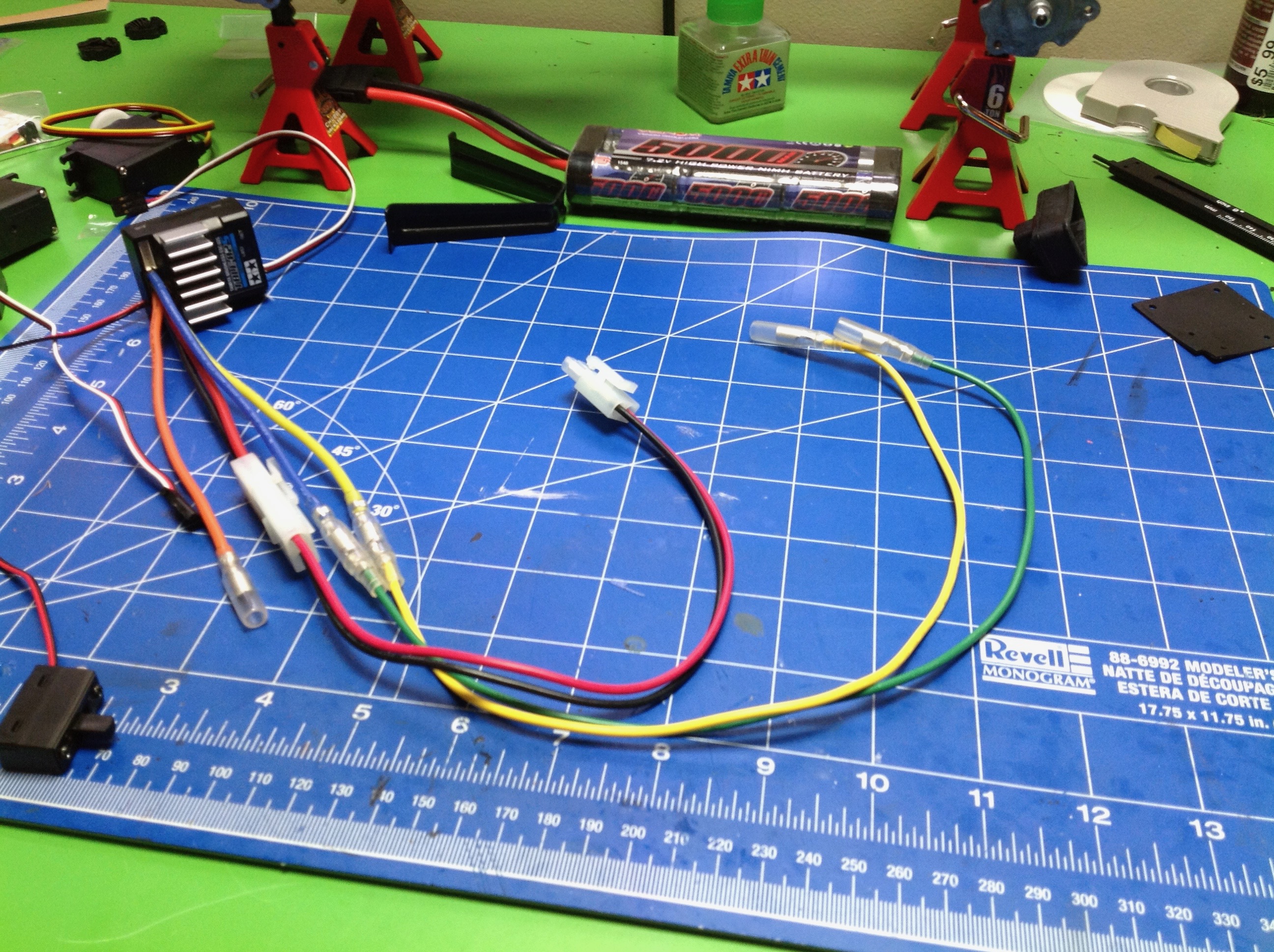
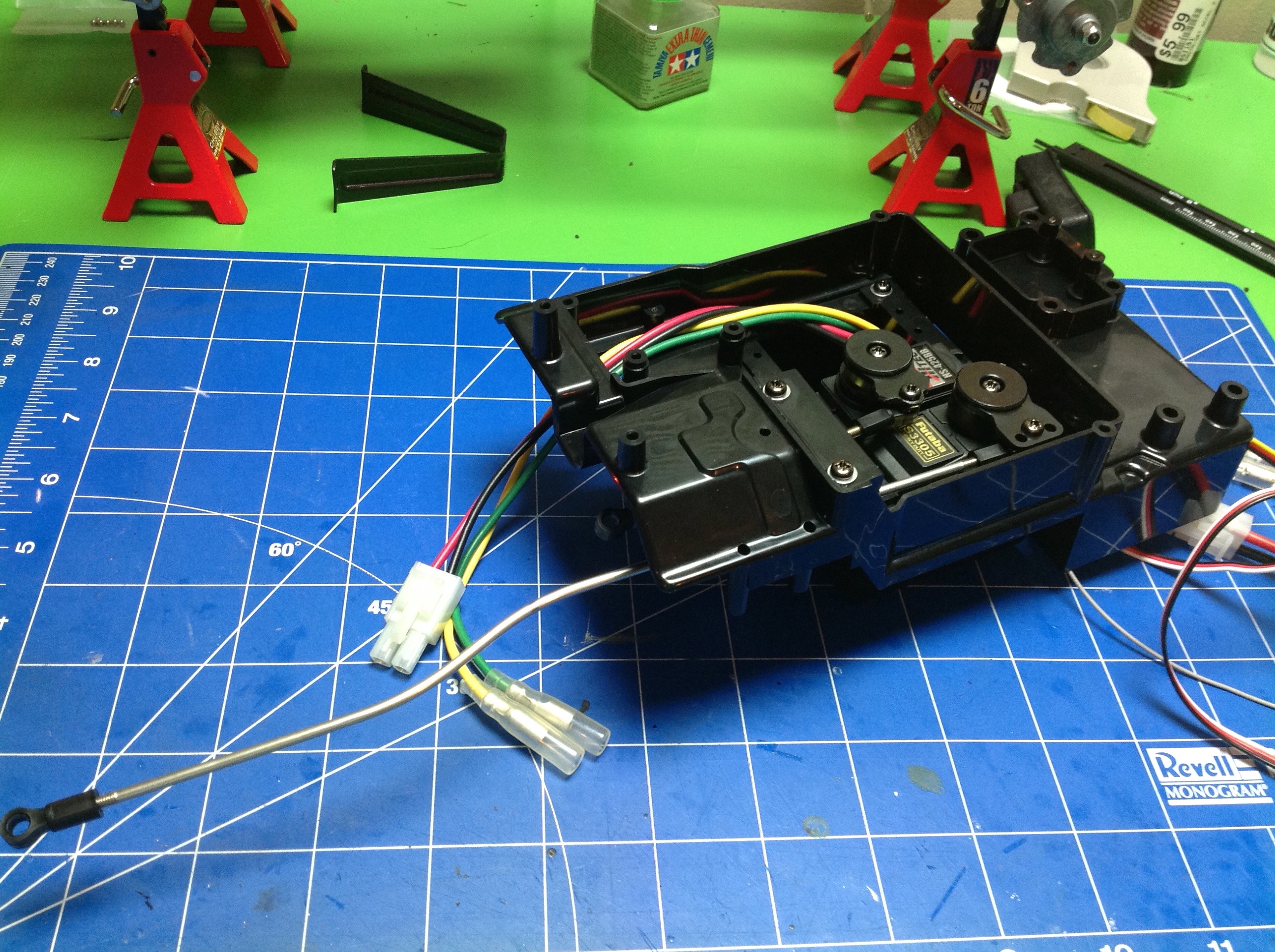
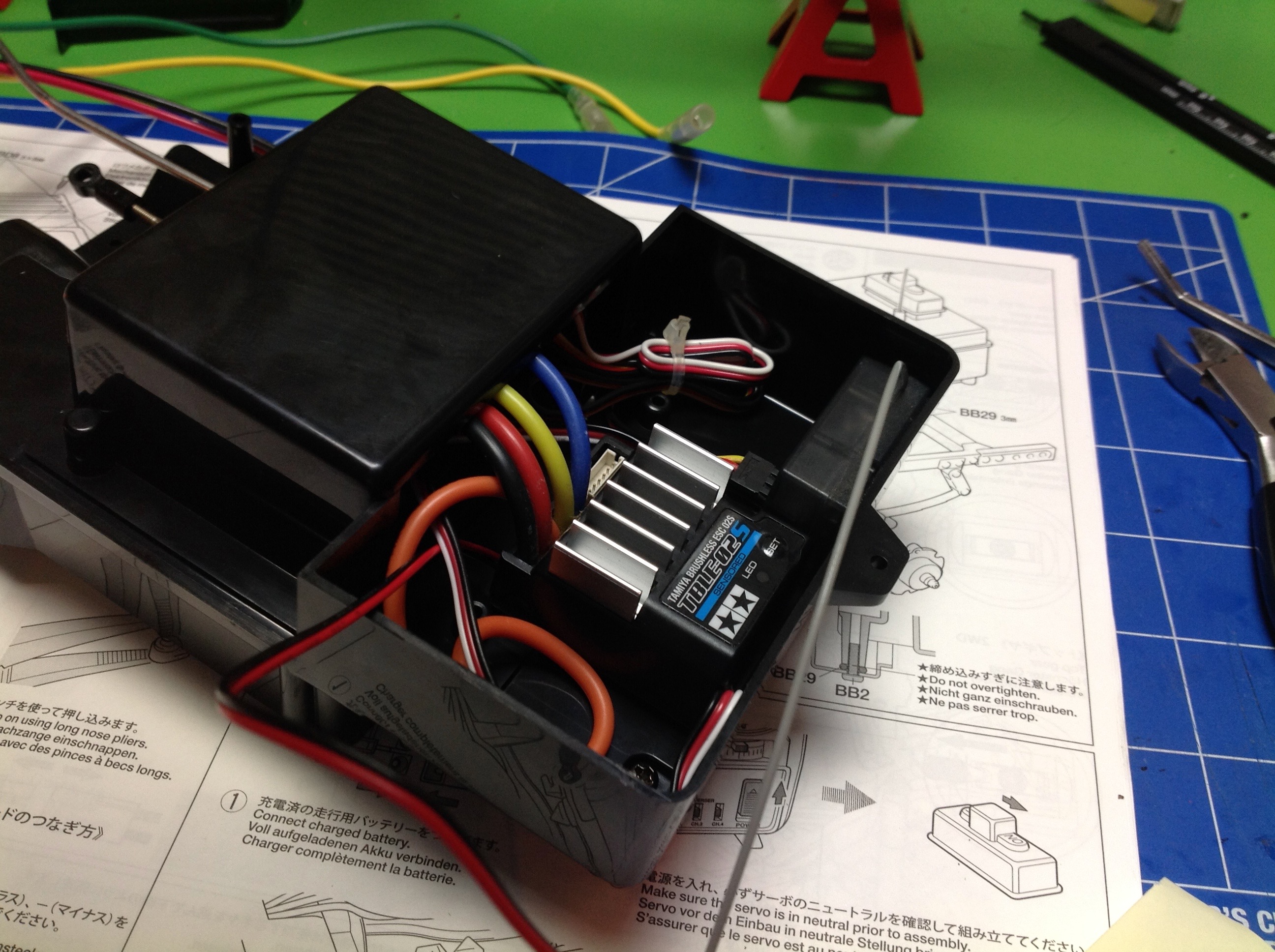
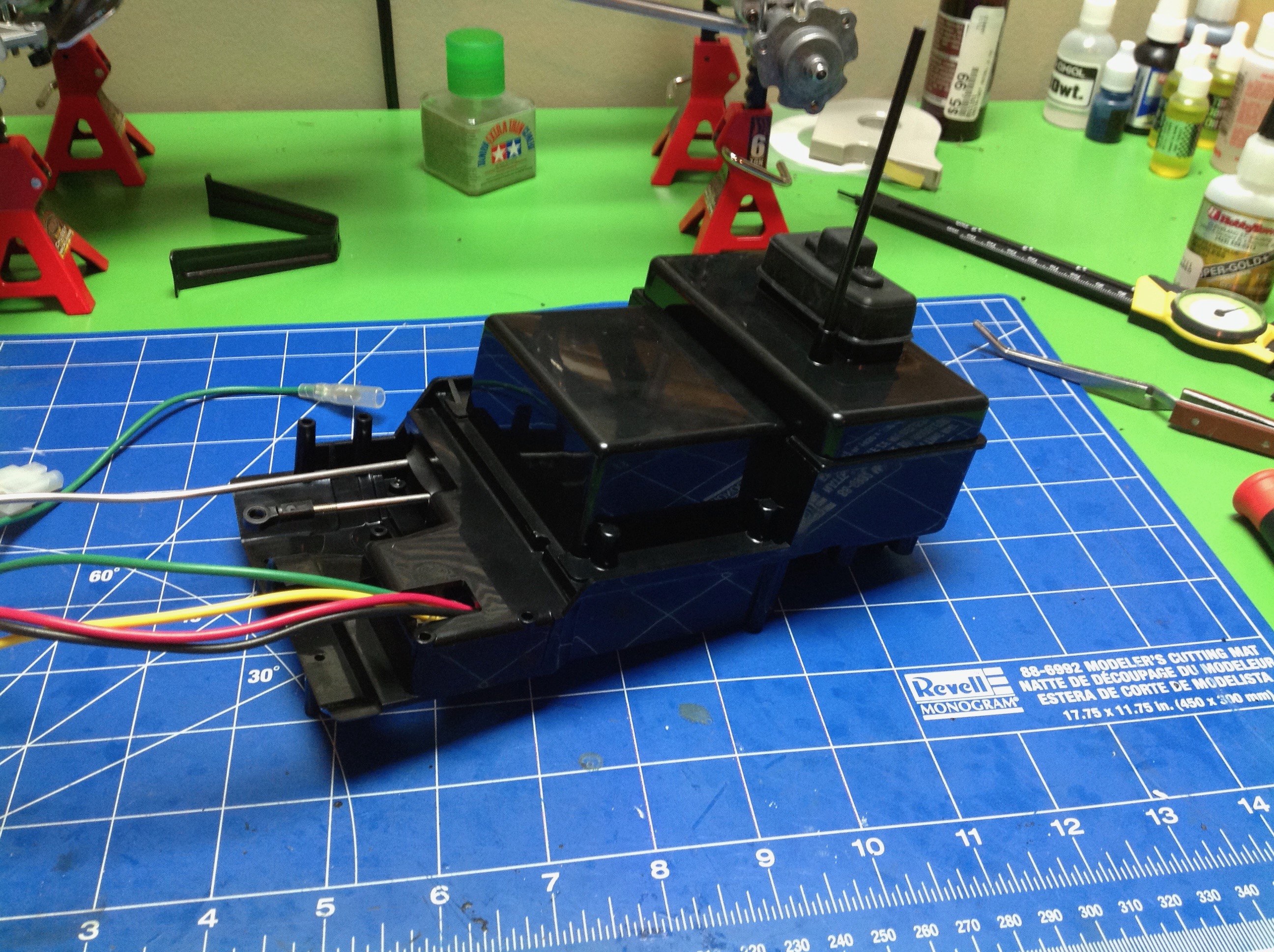
Now we flip the electronics box over and install the ESC, the receiver, and the power switch.
Because the box is so far back, both the battery wire and the motor
wires need extensions which are included with the kit.
Now the electronics box is installed in the chassis and the wires are
connected. Some of the screws and washers are a little tricky to
get to here. Once installed, we can hook up the other end of the
ball end links for steering and shifting. Now is also a good time
to adjust the lengths and make sure the steering is straight at neutral
and the 3 shift positions work. I highly recommend using a
programmable radio which allows assigning a switch for shifting and adjusting the end points.
This is much easier than using a 2-stick radio with shifting on the left
stick as the instructions recommend.
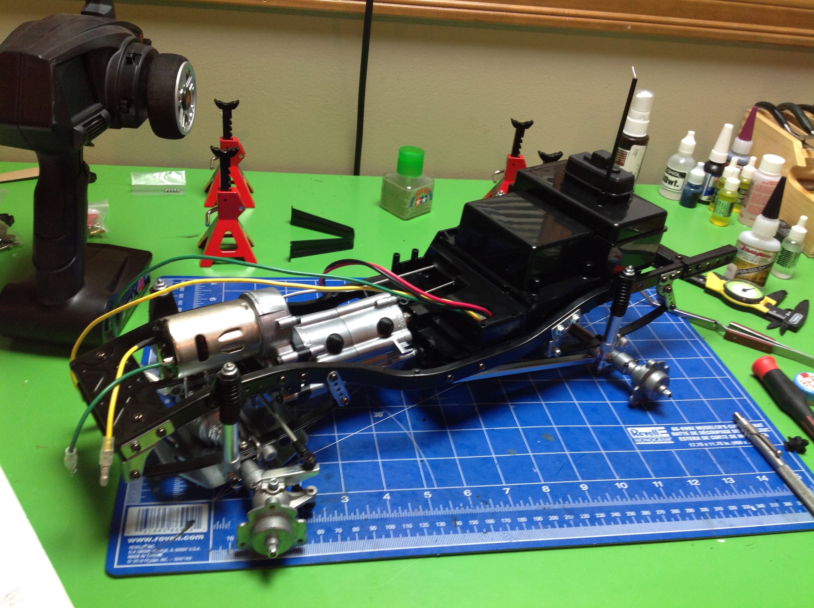
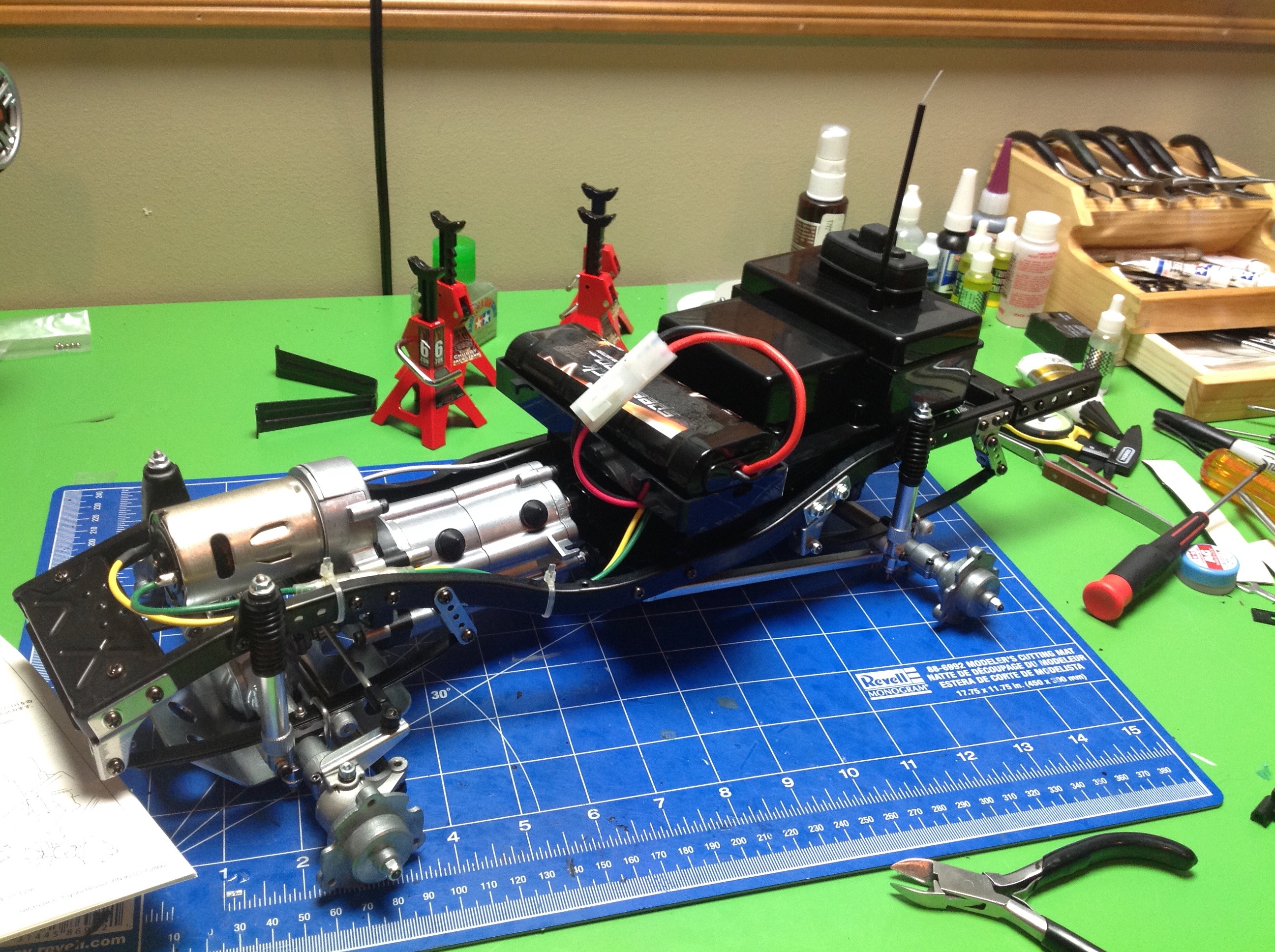
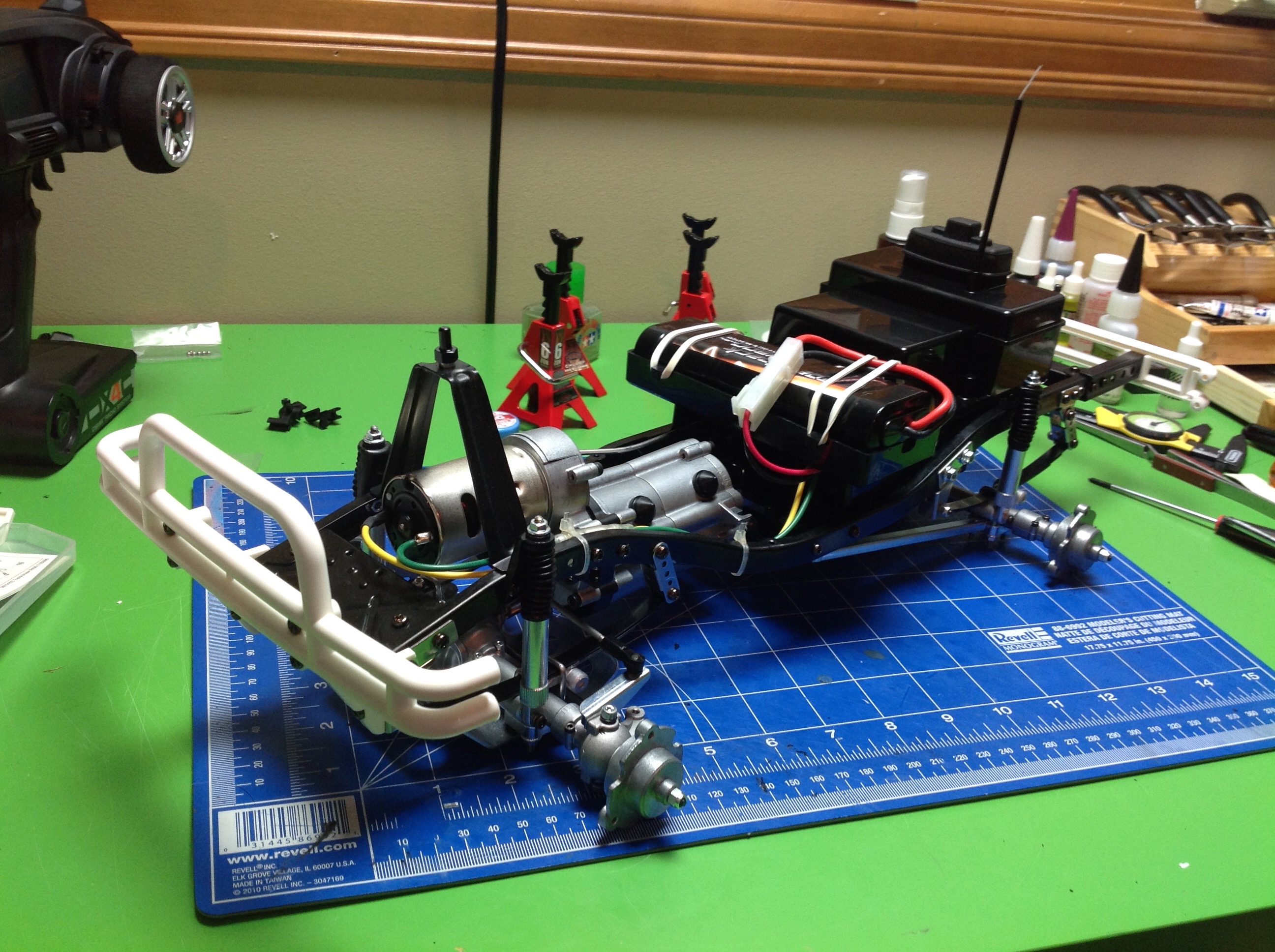
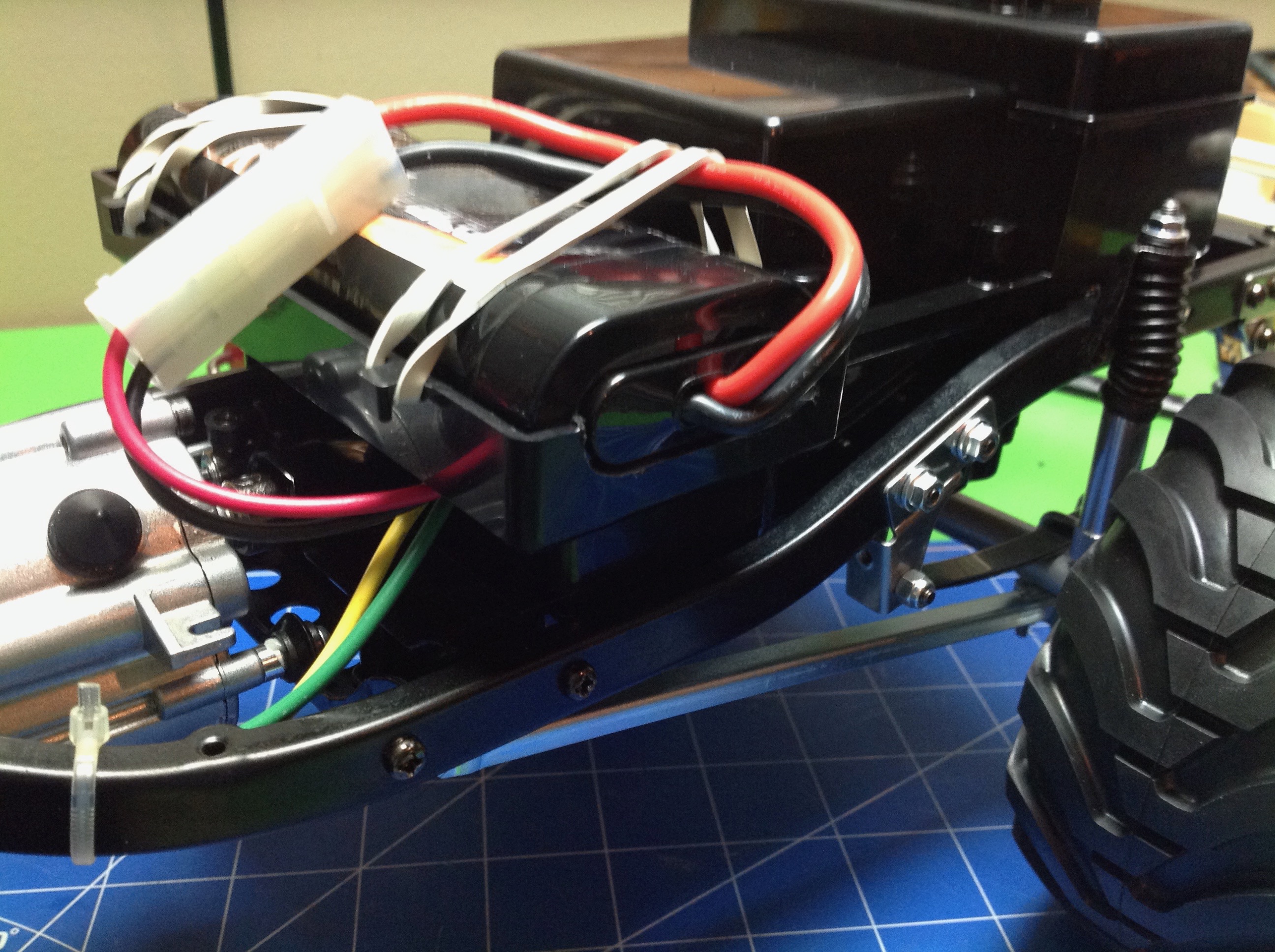
Next the tray for the battery is installed. The battery sits in
the tray and is held with rubber bands. Then the white plastic
bumpers are installed as well as the triangular body support above the
motor. The original Bruiser had a different battery tray that was
sized for the larger 6V pack available at the time. This tray is
from the Mountaineer.
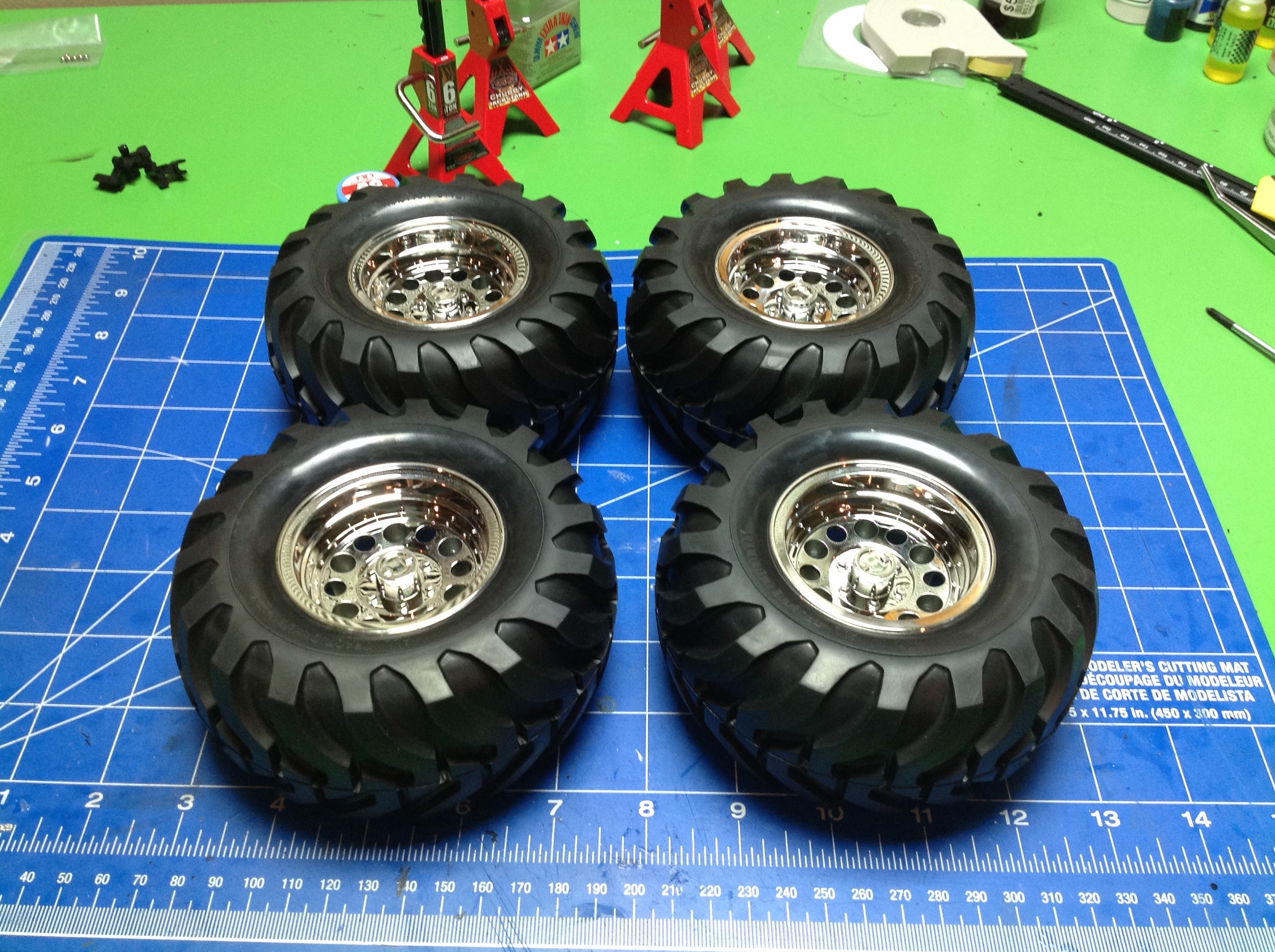
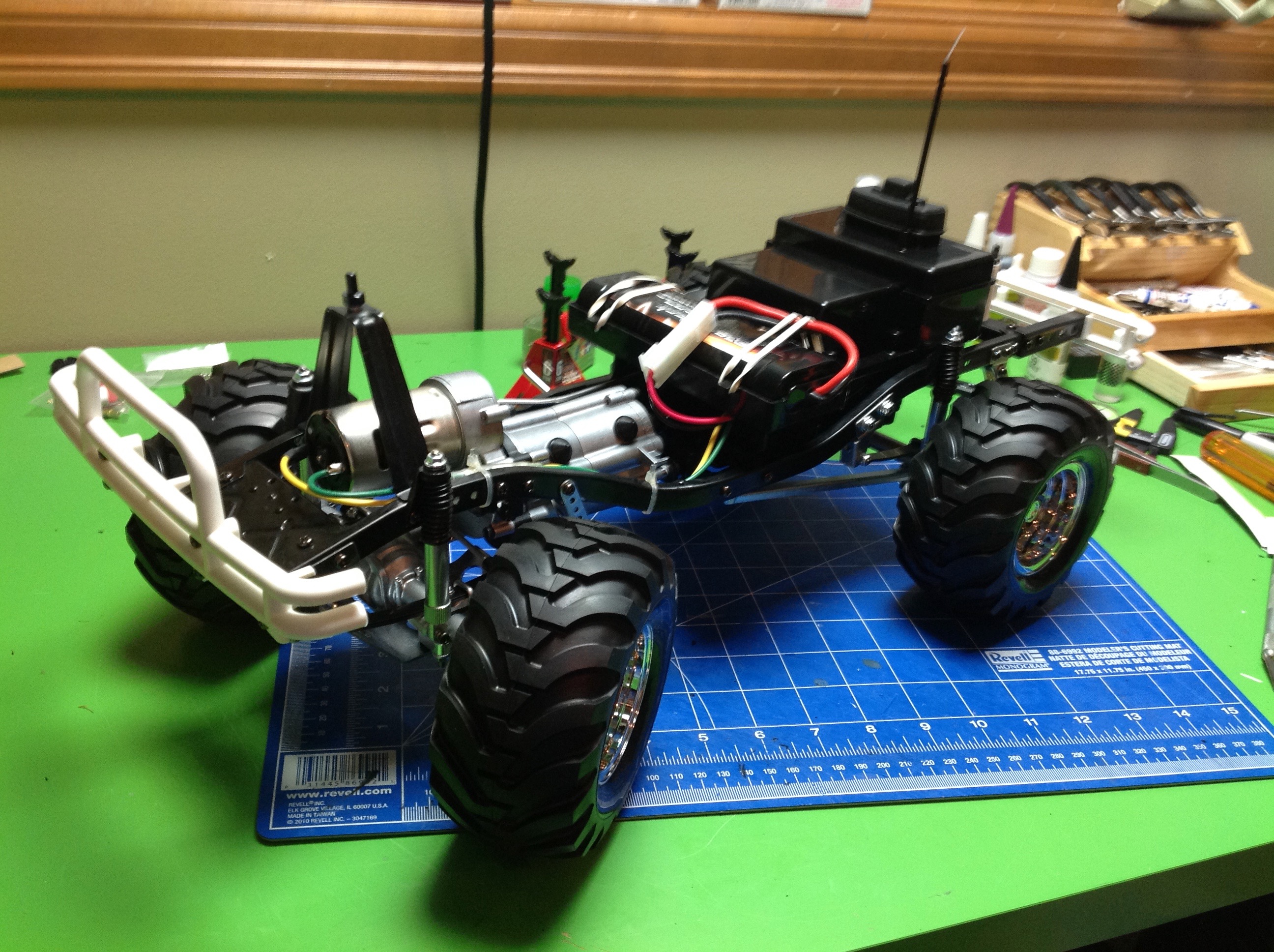
The final step in getting this thing rolling is installing the wheels
and tires. There is really no reason to glue the tires, and the
instructions do not tell you to do so. The tread is directional
though, so make sure you get it facing the right way on each side of the
vehicle. The tires are quite stiff and there are no foams.
The original Bruiser actually used beadlock wheels, not one piece wheels
like these. The later Mountaineer used these wheels though.
One modification I made immediately was to use a Dremel to enlarge the
end of the battery tray slightly to allow the use of longer
batteries. This made my standard packs fit much better. LiPo
batteries tend to be even longer, but they honestly don't offer much advantage
on a model like this.
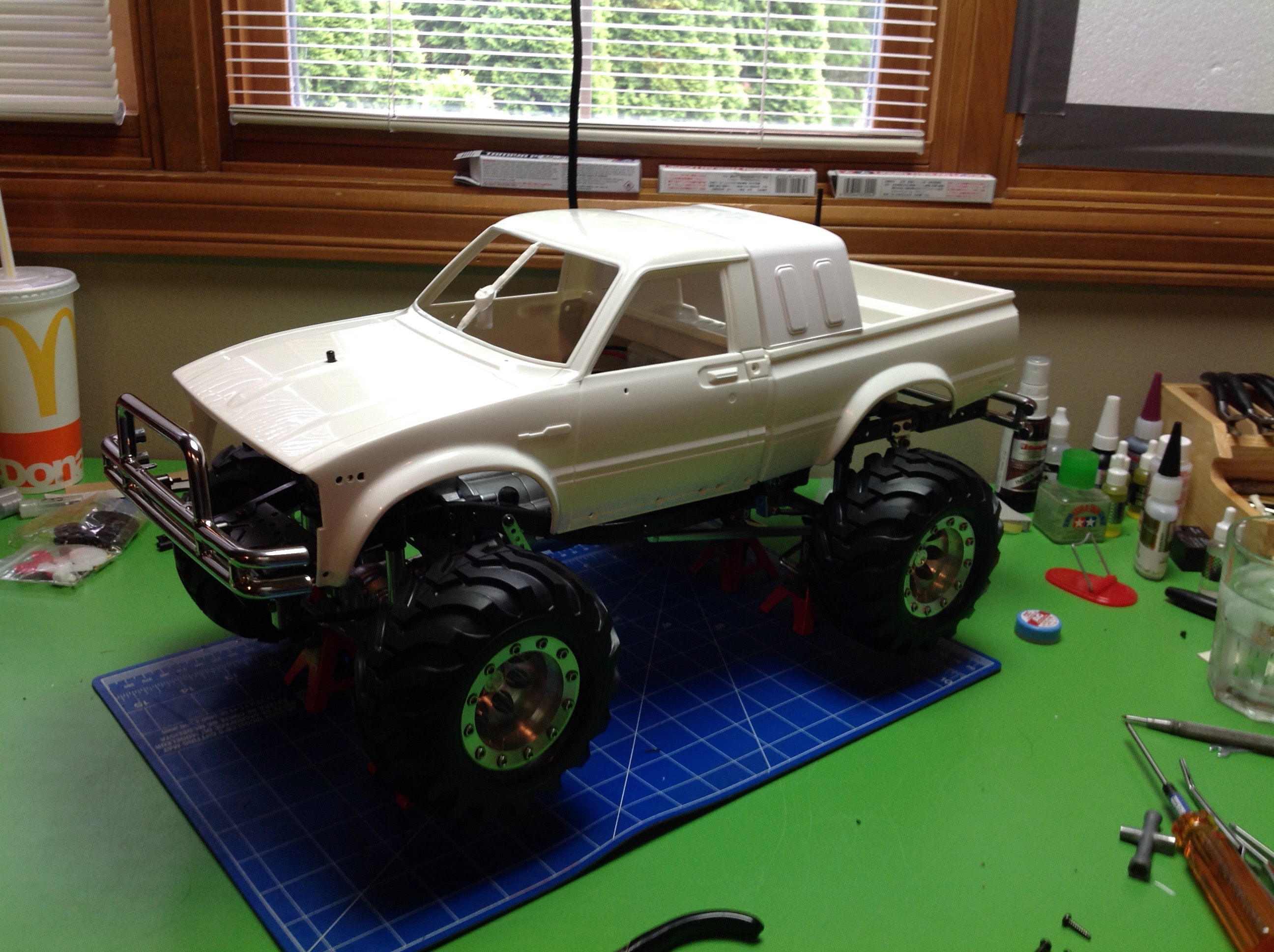
At this point it seemed only reasonable to dry fit the hard shell body
onto the chassis to see how it looks. It looks real good!
©2017 Eric Albrecht