King Hauler Project

Tamiya King Hauler Project

Page 2:  Building the Suspension


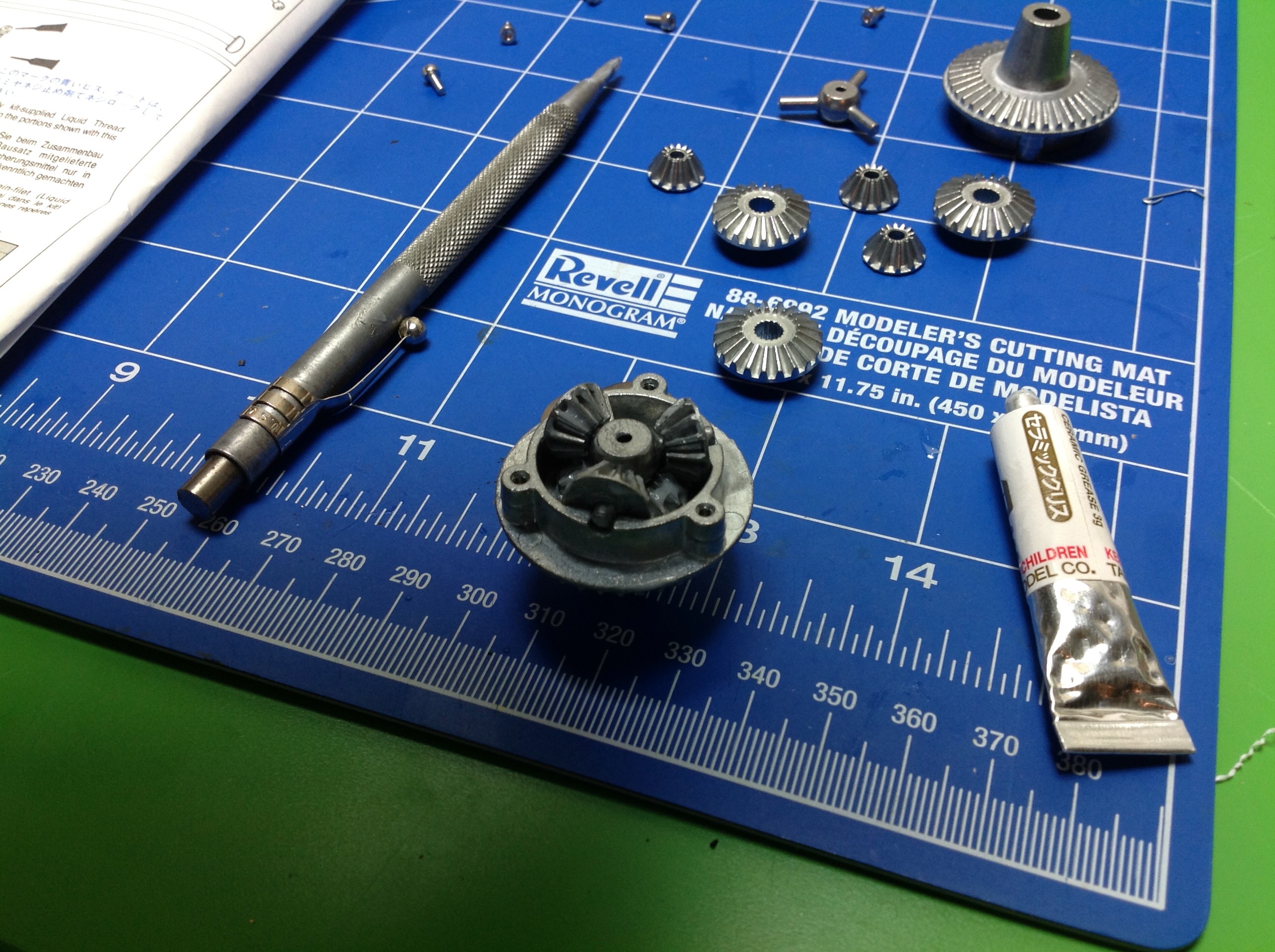
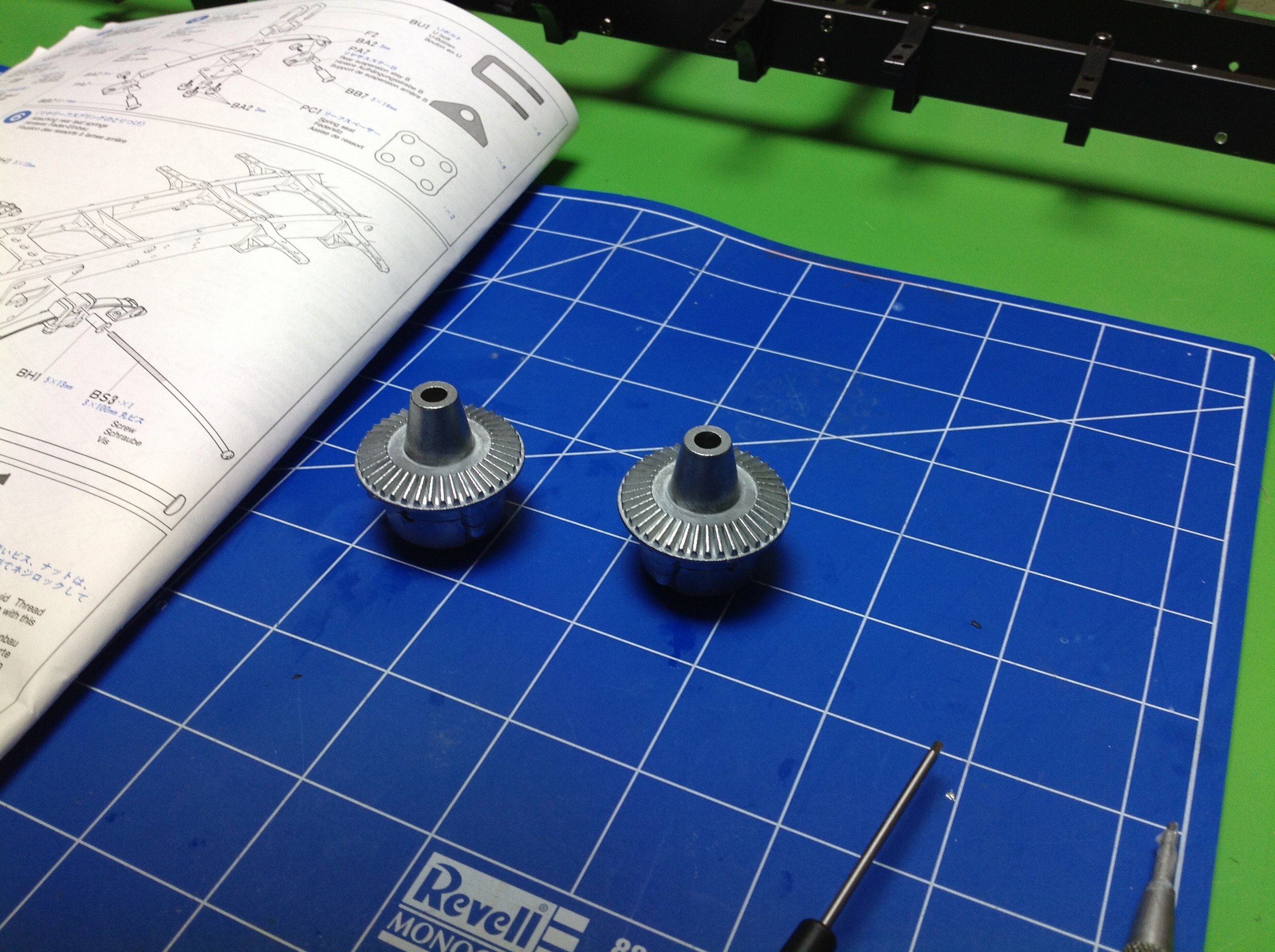
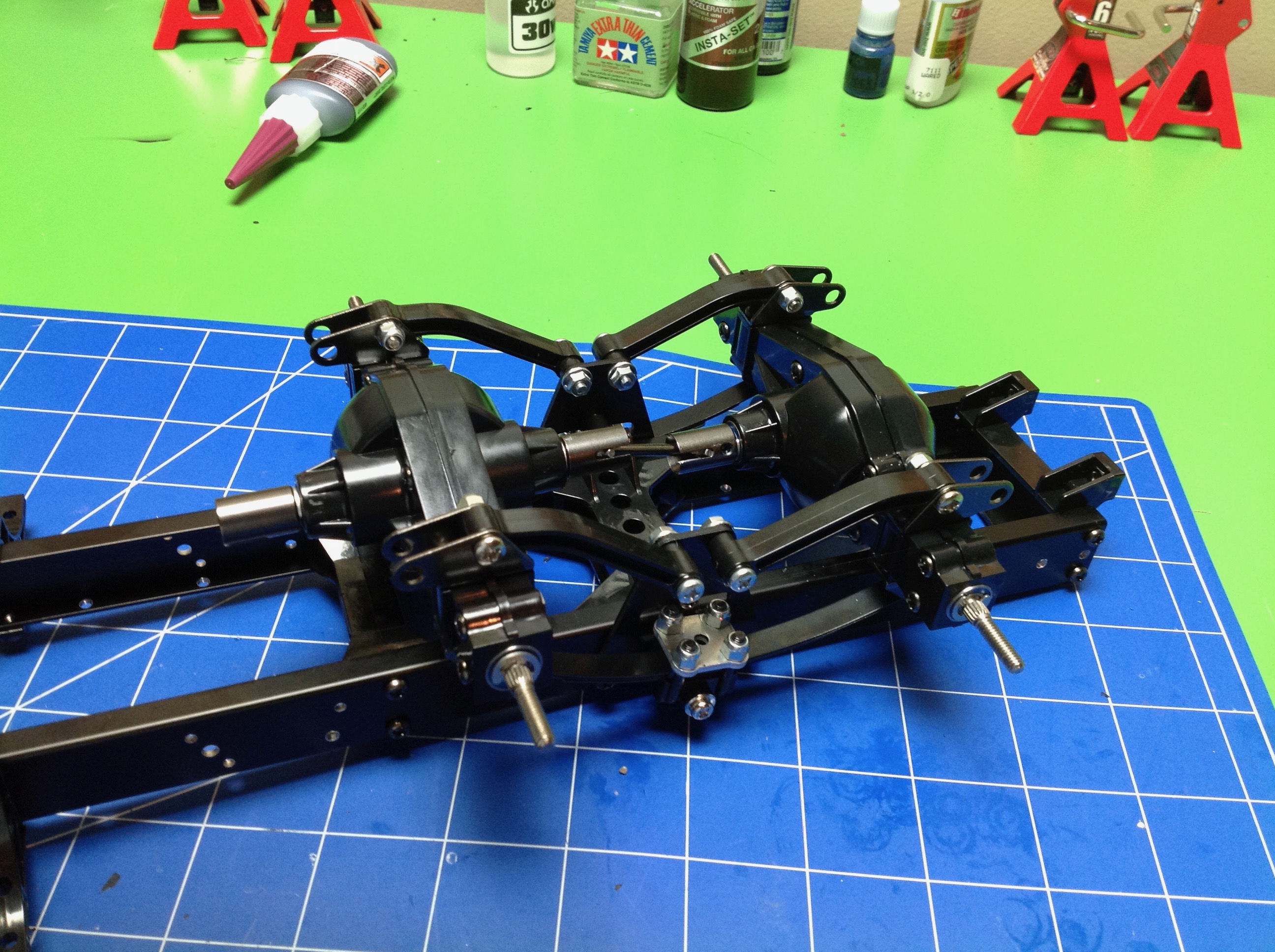
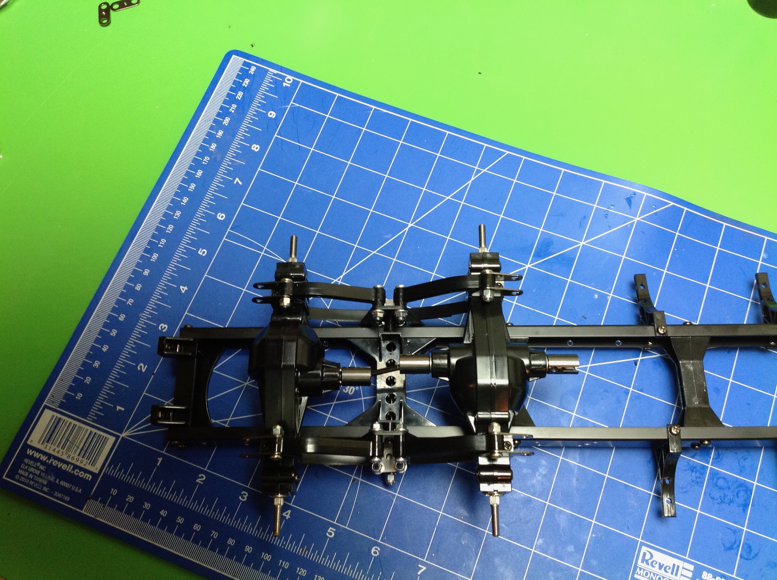
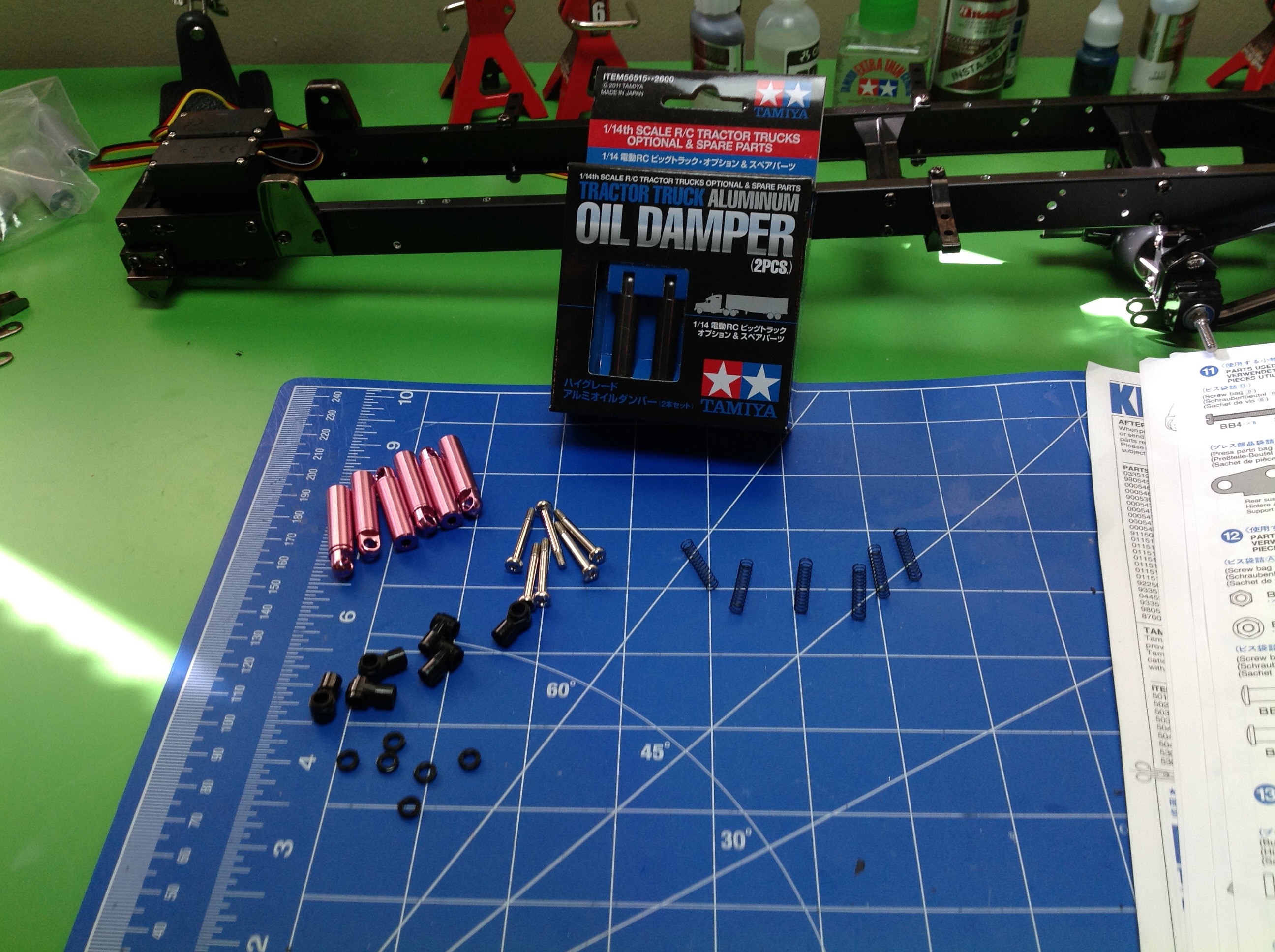
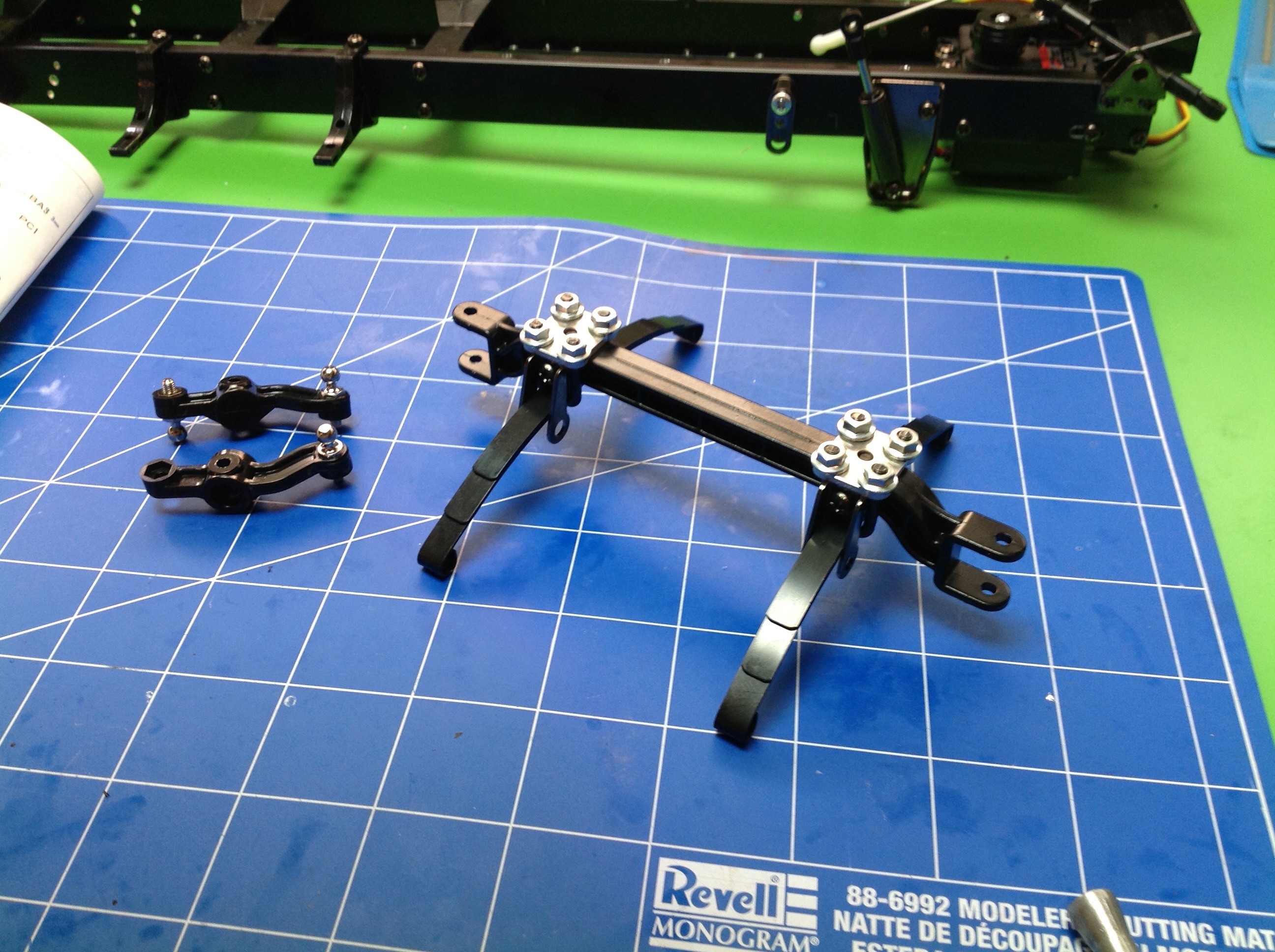
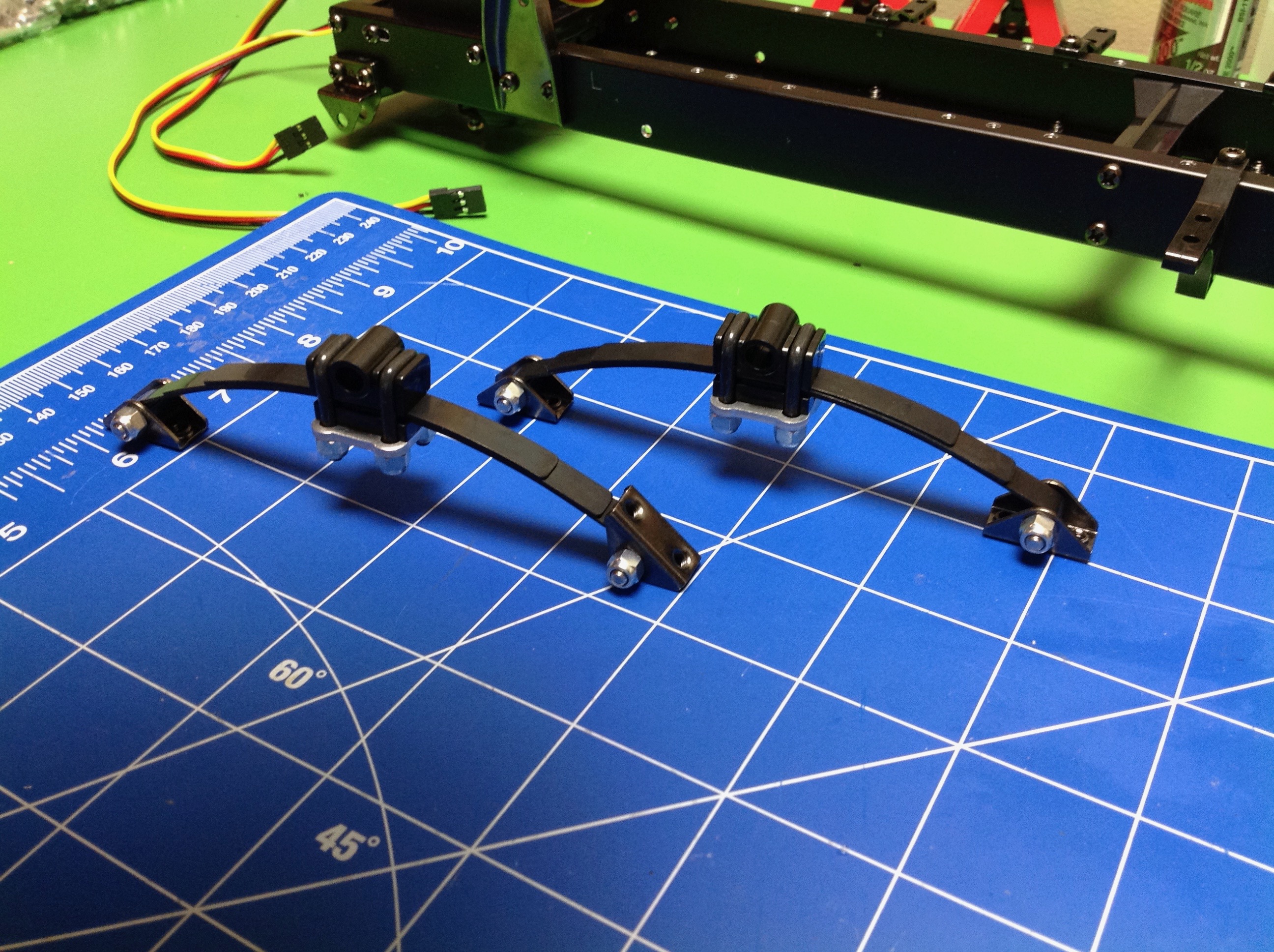
Step 5 builds the rear leaf springs.  Each semi-elliptical spring contains 3 leaves which are cross bolted and then clamped with U-bolts.


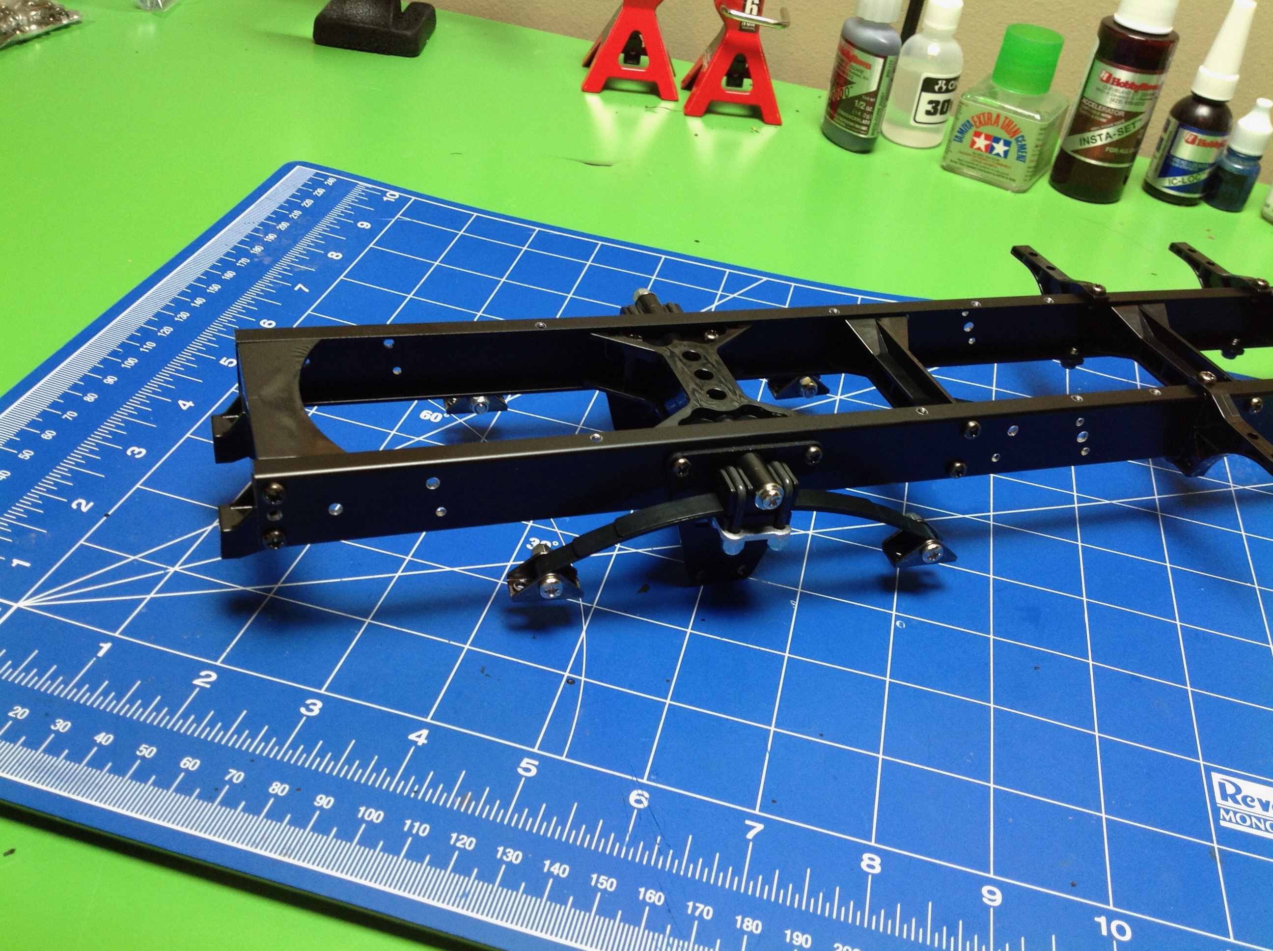
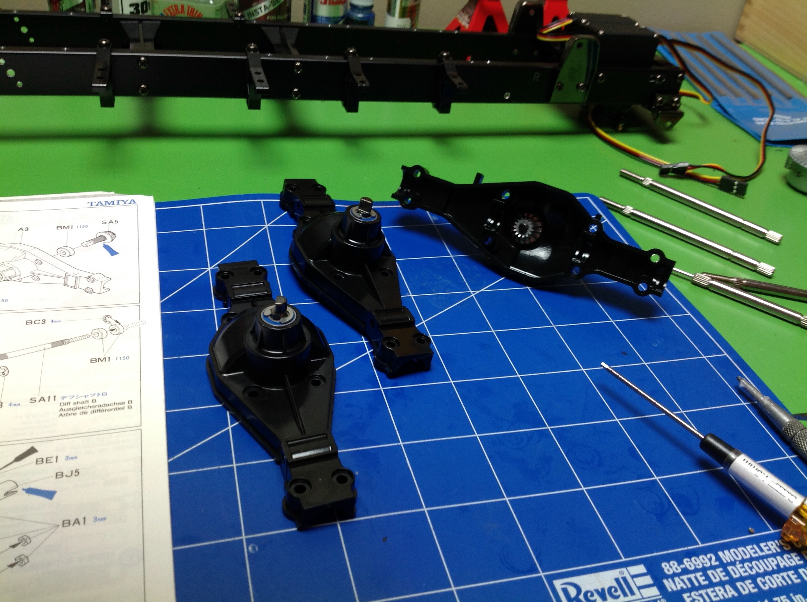
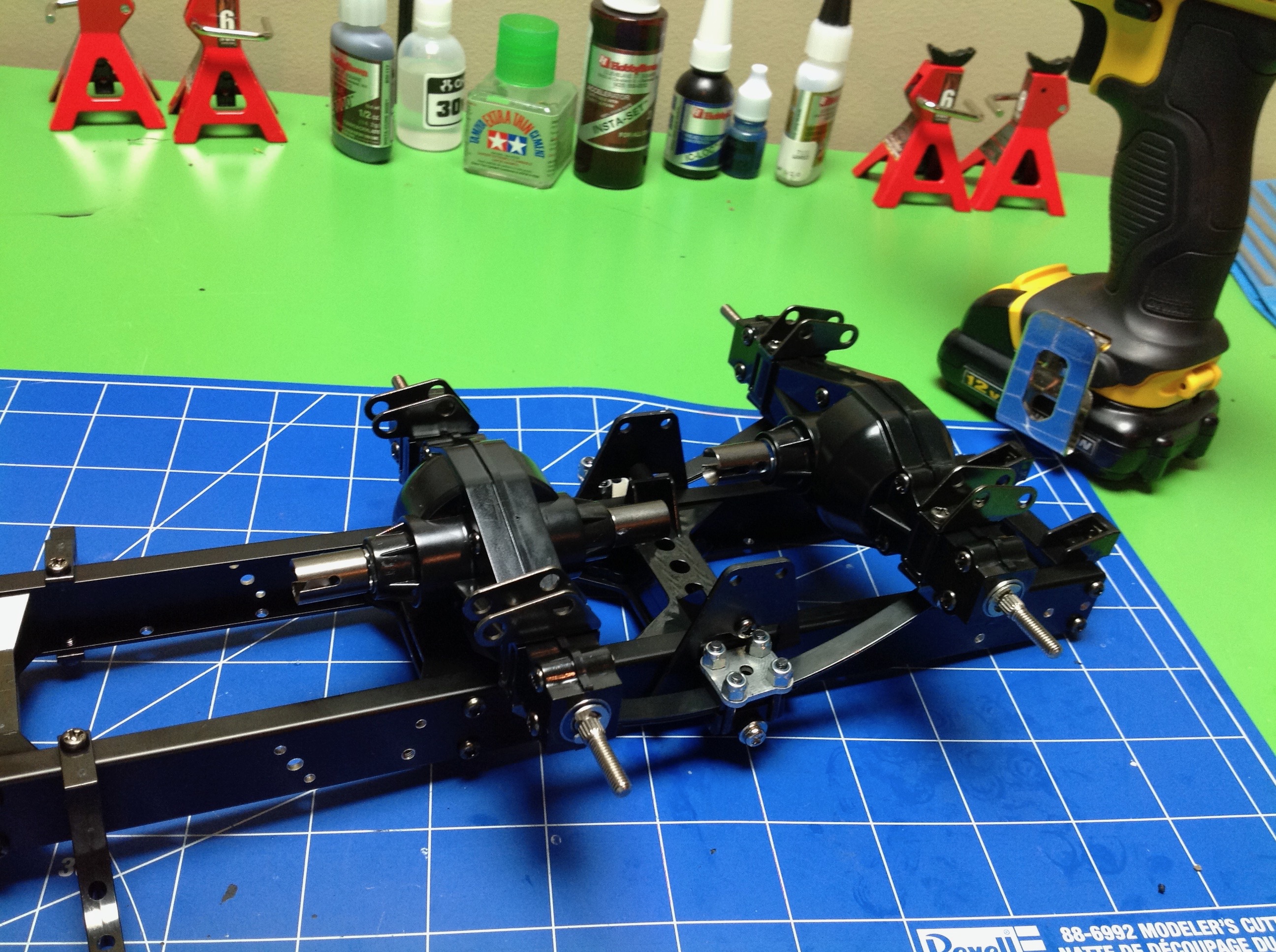
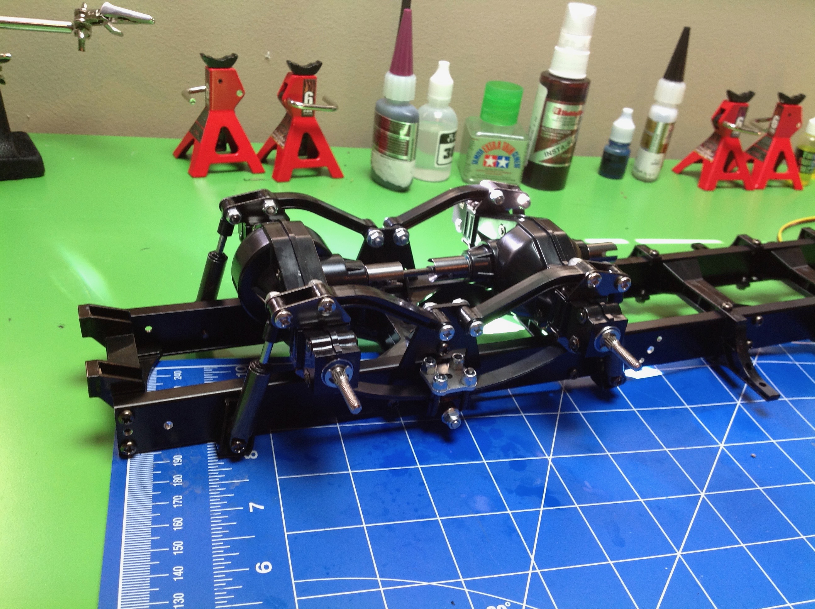
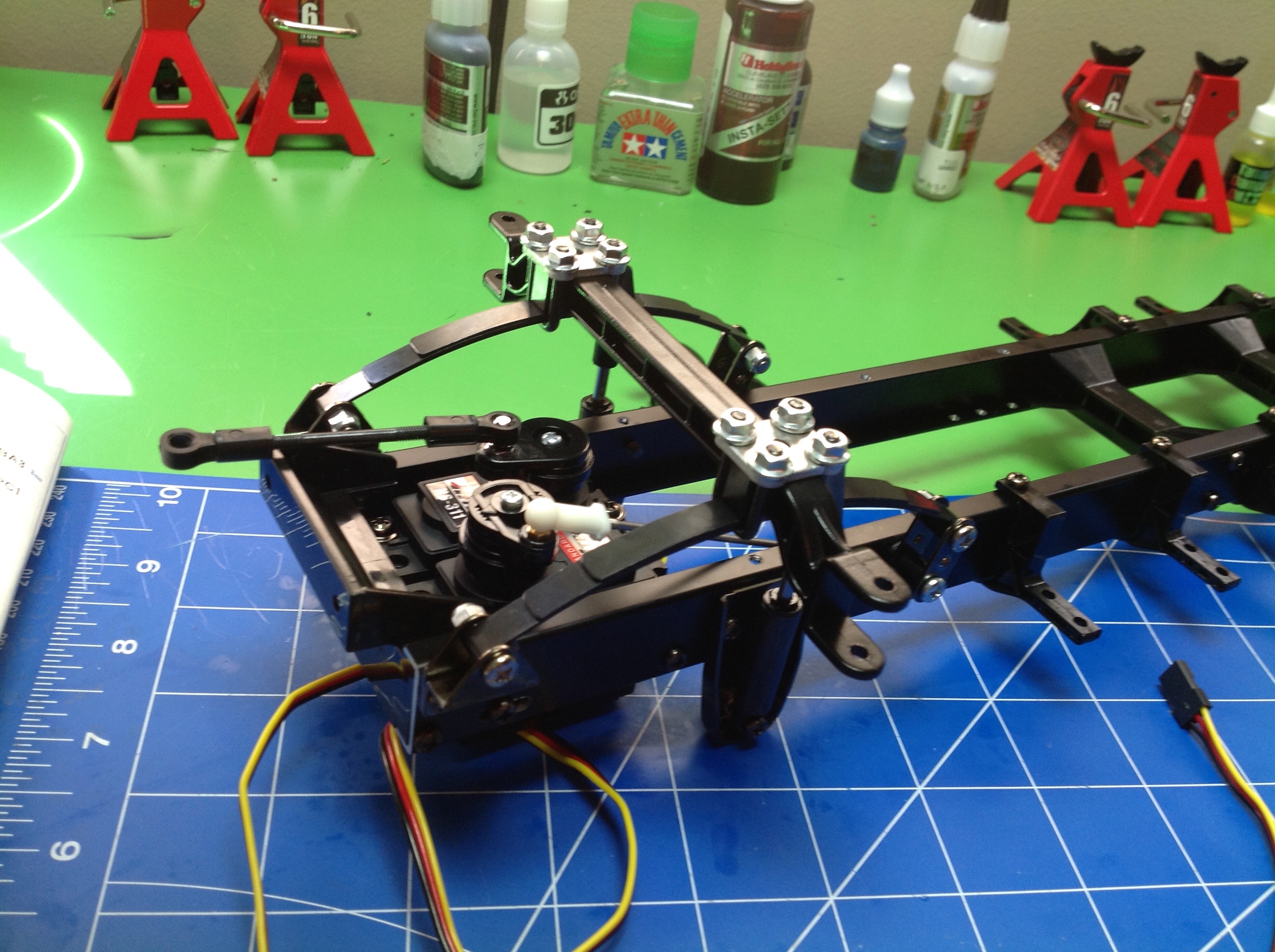
Step 6 installs the rear springs to the chassis.  The spring needs to be able to pivot because it is going to be supporting both rear axles.  It is installed with a shoulder bolt which prevents the possibility of over-tightening which would prevent free rotation.


Step 7 builds the rear differentials.  All of the internal gears, the housing, the ring gear, and the carrier are metal.  The kit comes with ceramic grease to lubricate the gears and make them run smooth.  This a true open diff with almost no resistance, so you will lose traction quickly if any wheels come off the ground.  The fact that both rear axles are powered helps.  It is possible to use Tamiya anti-wear grease instead of ceramic grease to increase resistance so the gears don't slip so easily, but I didn't find out about this until after my build.  On pavement it doesn't really matter, but if you want to drive some scale logging roads you may want to do the mod.


Now it is time to start building axles.  I had read that this model comes with bushings rather than ball bearings, which is correct.  You can see the bronze bushings in the bag.  I went ahead and ordered a full set of rubber sealed ball bearings from Advantage Racing and installed them right away.  It is unfortunate that I never even tried but the stock setup, but I don't regret the upgrade.


Step 8 builds 3 sides of the axle housings.  Why 3?  The front side of both axles is the same, containing a pinion gear and a bearing.  However, the front axle also has a pinion coming out the back to go the rear axle, while the rear axle has nothing on the back.  Keeping the parts straight was actually a bit tricky because they are so similar.


Step 9 builds the live axles.  Each axle consists of a metal splined shaft with snap ring grooves.  The splines are inserted into the sockets in the differentials, and E-clips secure the bearings.


Step 10 installs the axles into the housings.  Here you can clearly see the difference between the 2nd and 3rd axles.


Step 11 installs the axles by bolting them to the ends of the leaf springs.  This is a good time to mention the importance of thread lock.  All these metal parts are subject to vibration and the screws will back out if they are not locked.


Step 12 installs the plastic radius arms and the rear drive shaft.


At this point I ran into a problem: the axles did not attach properly.  Something was misaligned and the suspension would not articulate smoothly.  I did not want to continue building without resolving the problem.  It took me a while to discover the cause, but the first image shows it.  The leaf springs were not parallel to the clamps.  In the first image the clamp is flat on table but the spring has a significant slope to it (gapped on the right).  The second image shows how much I had to tear apart to fix the problem.  Thankfully, since everything is screwed together it can be disassembled and reassembled easily.


Now everything is straight and true and works much better.


Step 13 builds the "dampers".  The dampers that come with the kit don't really damp at all.  They are just spring cartridges and are mostly for show.  I ordered 3 sets of the hopup oil dampers from Tamiya to use instead.  I was a bit worried when I saw that the stock dampers were sprung, because I feared the unsprung oil dampers would effect the ride height.  However, the spring force in the dampers is very small so it doesn't really matter.  The first image shows the parts needed to build the stock dampers which include aluminum housings.  The oil dampers must be built up from plastic and aluminum parts, filled, and bled.


This image compares the completed oil dampers with the stock dampers.  Other than the color, they look no different from the outside.  Having now built and driven the model, I can say that this upgrade is probably unnecessary.  The oil dampers are quite expensive and given that this model will only be driven on pavement anyway I doubt the handling will be noticeably different.  With that being said, I never actually tried it with the stock dampers so I can't be sure.


Step 14 installs the dampers.  Bushings and/or shoulder bolts are used to prevent clamping down on the shock ends.  I have to say, I love the way this suspension moves and sounds with the weight of the metal.


Step 15 builds the tie rods which must be very specific lengths.  You can see that two of them have open ball connector ends while the 3rd has closed ends for smaller balls.  Looking back on this later, I am amazed at the tiny diameter of these rods for such a big, heavy model.  I've never had the slightest problem with them though.


Step 16 installs the steering and shift rods along with the front dampers.


Step 17 connects the solid (plastic) front axle to the leaf springs and also builds the steering arms.


Step 18 installs the front axle to the chassis using the leaf springs and some shackles.


Step 19 installs the steering arms using simple vertical kingpins.  The long steering rod connecting the left and right arms is also installed.  It is important to get this length right so the axles are parallel unless you want some toe in your alignment.  It is nice to see that the steering link is behind the axle so it won't hang up on anything when driving off road.

Back to Page 1Up to Index | Go to Page 3
©2017 Eric Albrecht