Tamiya King Hauler Project
Page 3: Building the Transmission
The transmission is usually my favorite part. I love to see how
different manufacturers handle the design, even in the case of a
transmission with only one speed. In this case, the 3-speed
transmission is advertised as shift on the fly, so I want to see how
they do it.
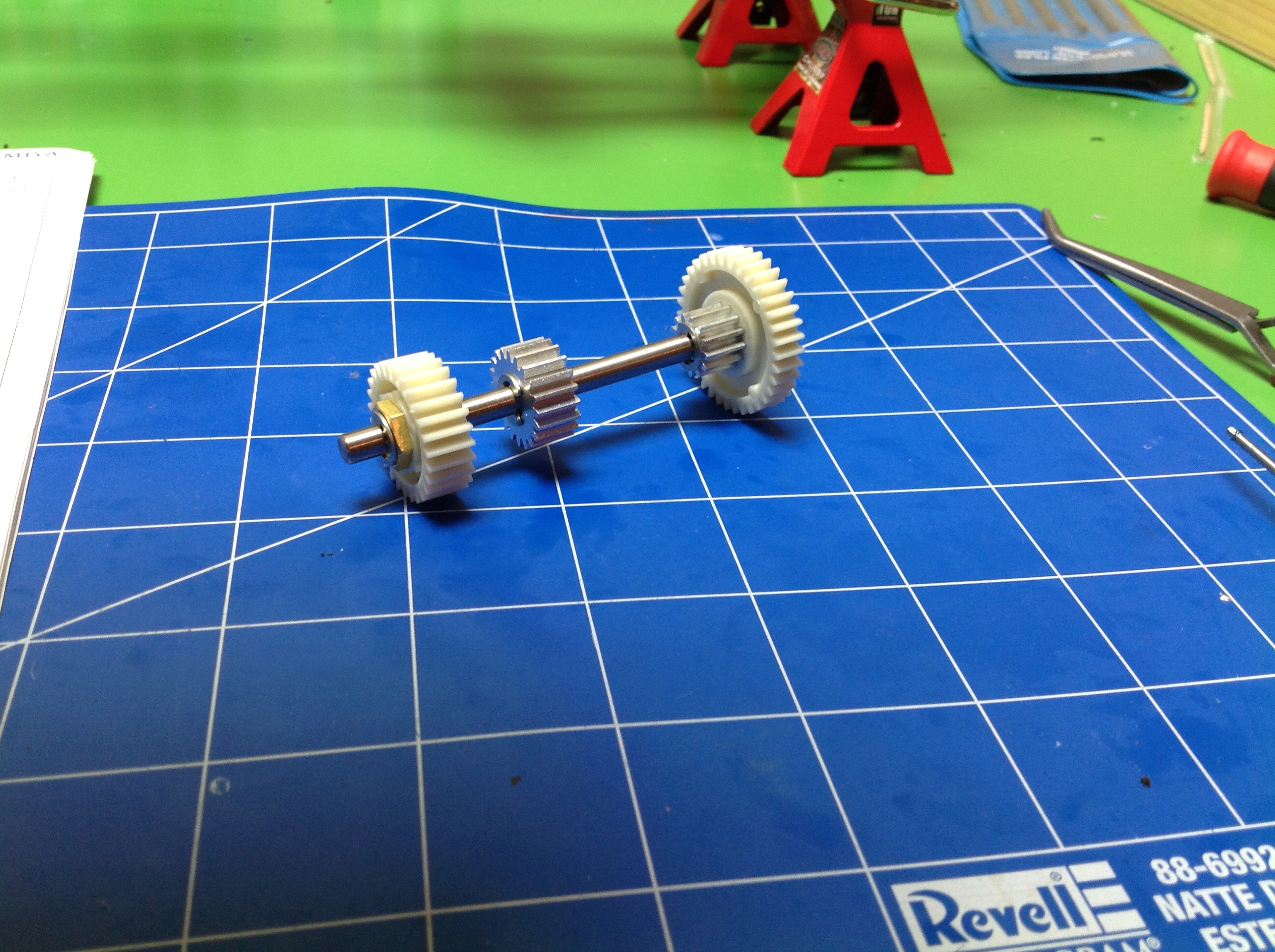
Step 20 builds gear shaft A. All 4 of the gears on this shaft are
locked to the shaft with splines. From left to right, the gears
are 27, 20, 13, and 36 teeth. The two smaller gears are metal
(apparently aluminum) and the larger gears are nylon. All have
wide faces. Shaft A, specifically the 36 tooth spur gear, is driven
directly by the motor so this is the input.

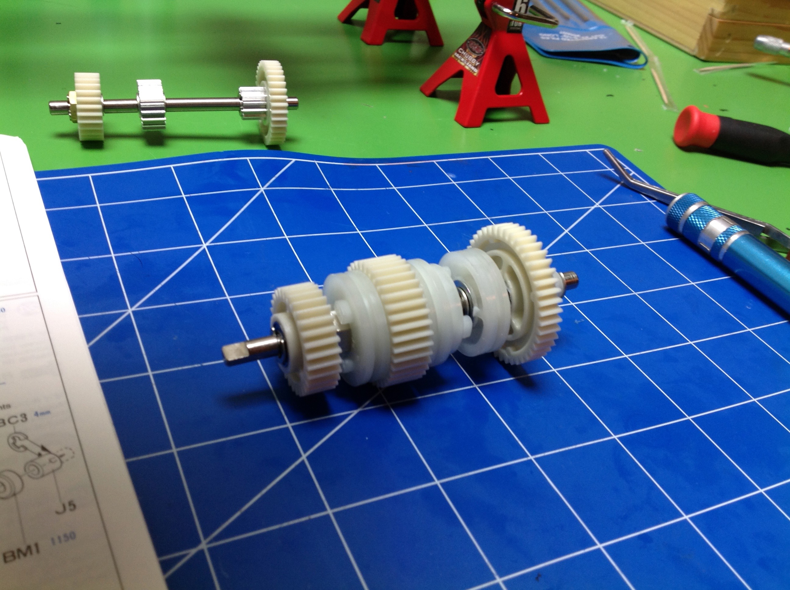
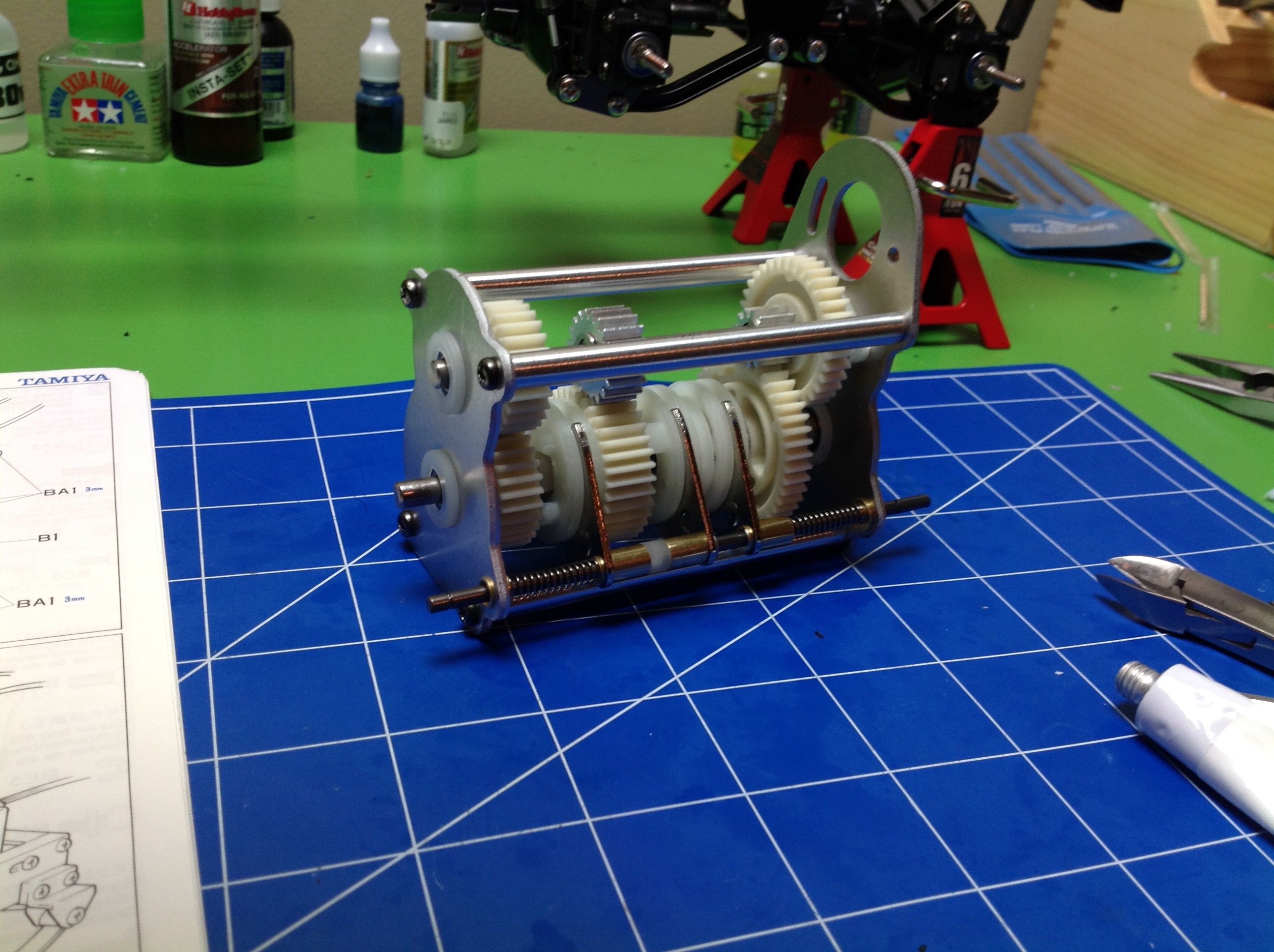
Shaft B is the output and is built in
Step 21. There's a lot more
going on here. From left to right, the gears are 30, 38, and 44
teeth. All 3 of these gears ride on bearings so none of them are
locked to the shaft. Instead, the 3 driving rings are splined to
the shaft. The shift forks will translate the driving rings and
cause them to mesh with one, and only one, gear at a time. The
driving
rings mesh with the gears through 3 driving dogs which allows them to
be engaged and disengaged while in motion, though obviously there will be
greater dynamic forces on the gears if shifted while moving.
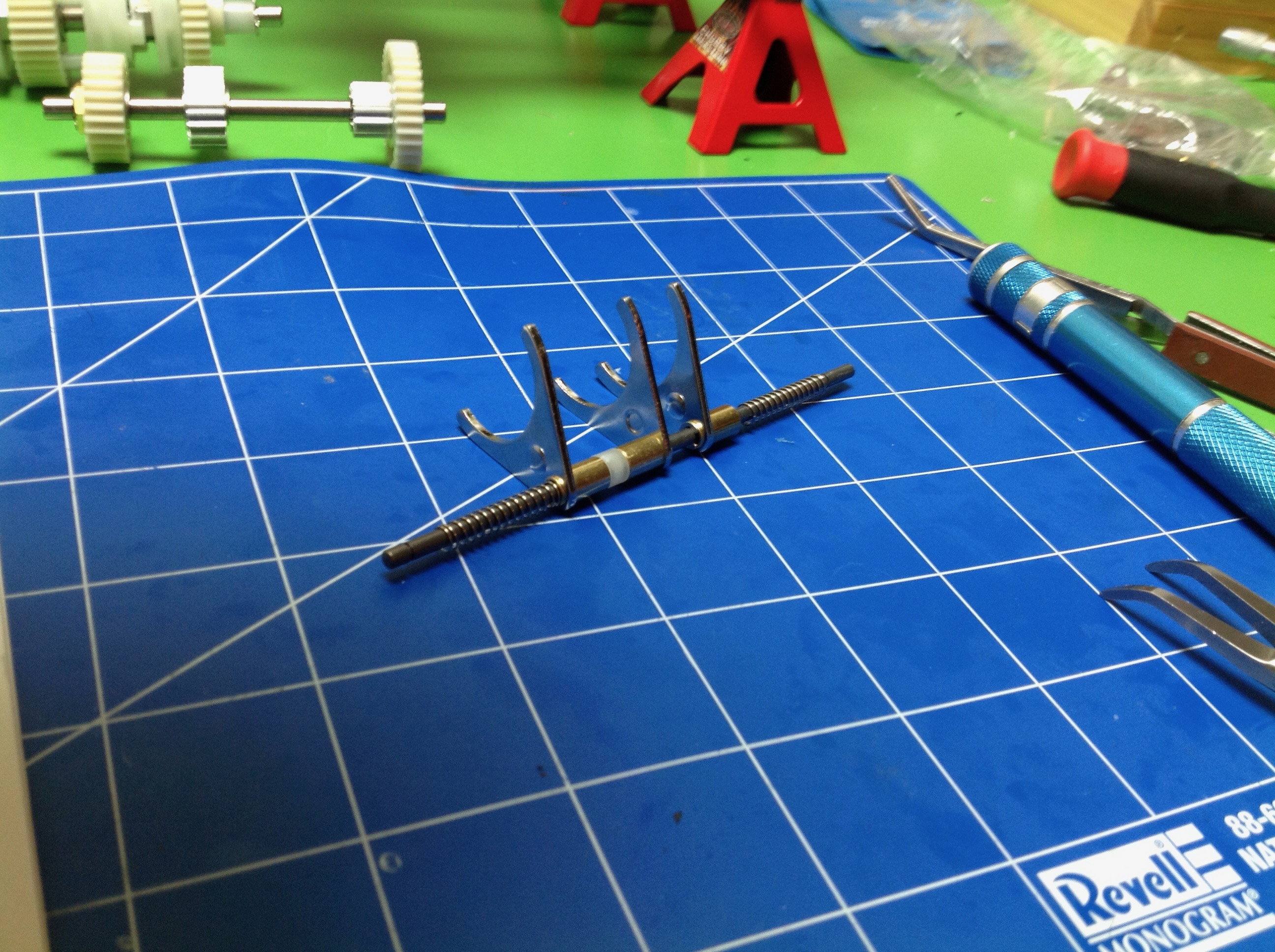
Step 22 builds the shift rod. The three forks will engage the
driving rings and must be able to translate them along shaft B. It
is important that the friction be low in the jaws. This rod will be driven by the shift servo.
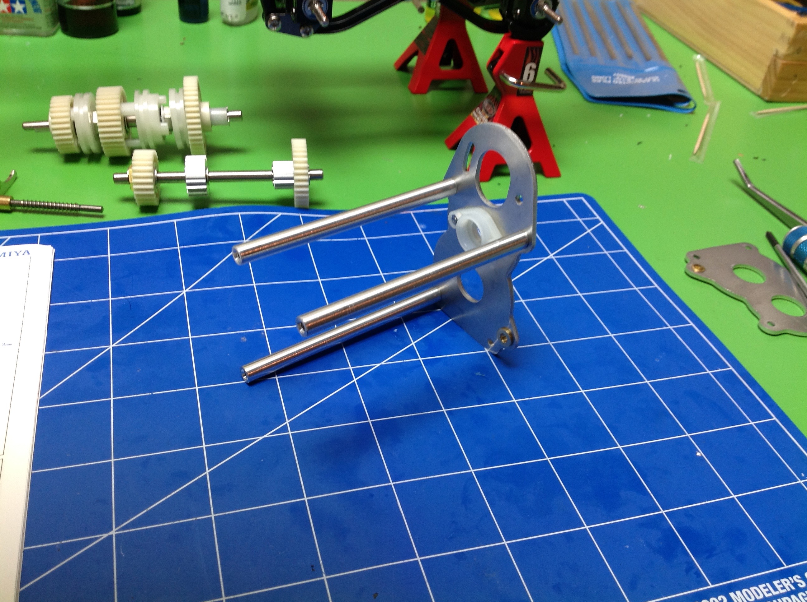
Step 23 begins the assembly of the gearbox supports. The 3 rods
shown are just structural spacers. The end plates will house
bearings to support the shafts.
Step 24 installs shaft A, shaft B, and the shift rod and closes out the
gearbox. Everything needs to be aligned and smooth running at this
point. I installed full ball bearings at this point. Some
later tractor truck instructions specifically recommend not installing
ball bearings on the sliding driving rings, presumably because the hard
steel bearing races can gall to the shaft. The King Hauler
instructions do not have this warning and I've had no problems.
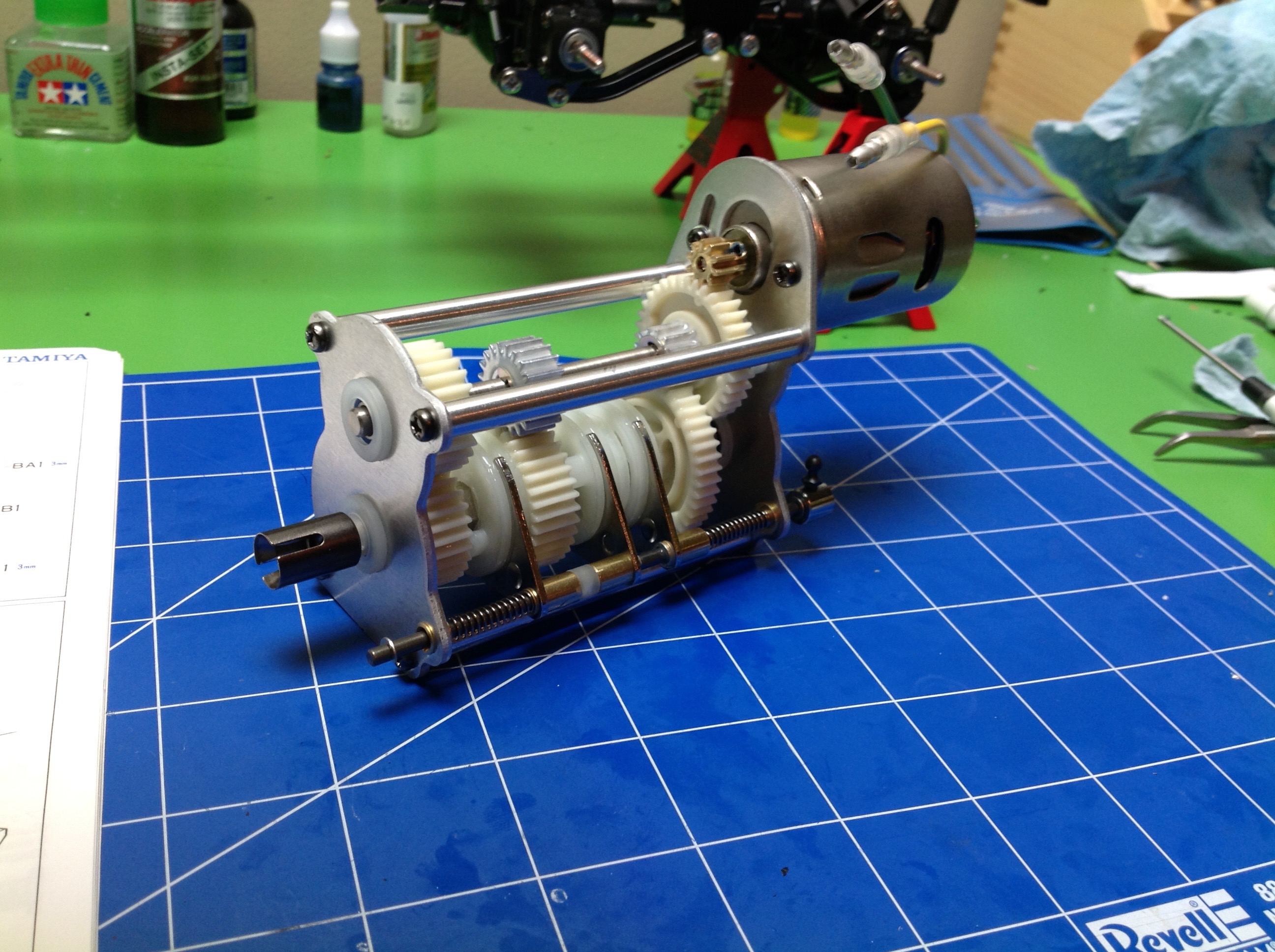
Now the Mabuchi 27 turn 540 brushed motor is installed in Step 25,
completing the gearbox. Looking at the 3 gear meshes, the
reduction ratios are:
- 1st - 44:13 = 3.38:1
- 2nd - 38:20 = 1.9:1
- 3rd - 30:27 = 1.11:1
So there is a substantial difference between gears. Of course
these are only the transmission ratios. The motor uses a 10 tooth
pinion so the motor ratio is 36:10 = 3.6:1. The final drive ratio
in the differential is 40:15 = 2.67:1 (if I'm counting the teeth
right). So the final ratios are:
- 1st - 3.38 * 3.6 * 2.67 = 32.49:1
- 2nd - 1.9 * 3.6 * 2.67 = 18.24:1
- 3rd - 1.11 * 3.6 * 2.67 = 10.67:1
This almost matches what's on the box, but
for some reason 2nd gear is off by 3%. I suspect they used 37
teeth instead of 38 for their math because then you get their
number. After some further investigation, the middle gear actually
has 37 teeth even though the manual says 38. So the box has the
right ratios but the manual has the wrong description of the gear.
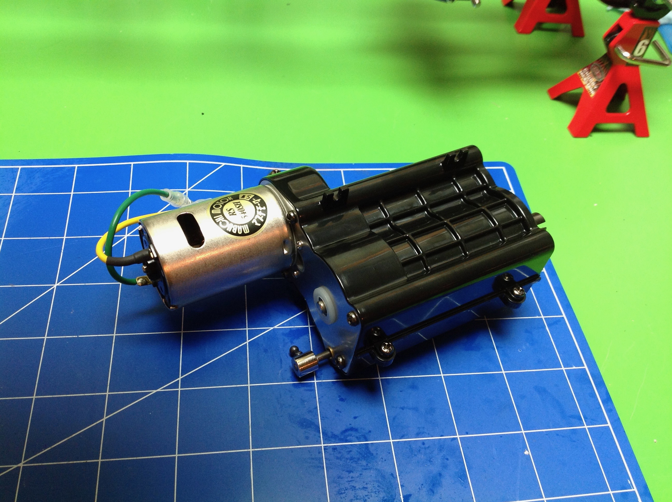
Step 26 puts a protective housing around the transmission to enclose it
after everything has been well greased. I must have used too much
grease in my axles because mine was already gone when I got to this
point so I used some Traxxas grease. It is shame that all this
mechanical goodness is hidden. I almost wish the housing was transparent but I suppose then you would just see grease.
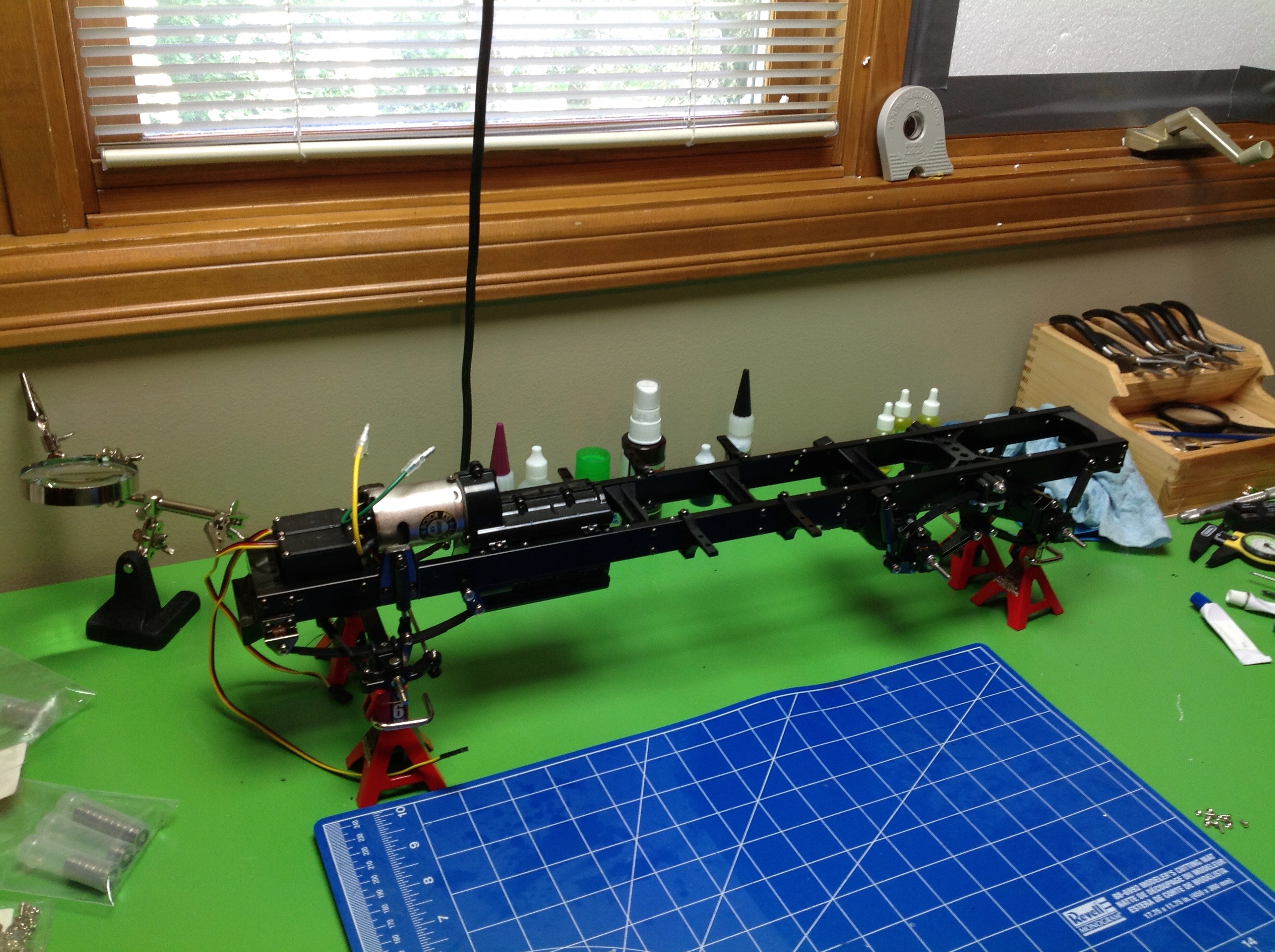
Step 27 installs the transmission into the chassis along with the main
drive shaft. At this point, all the main running gear is installed
and it is possible to fire up the motor and watch the chassis run.
©2017 Eric Albrecht