Features
|
| Aesthetics |
|
Styling
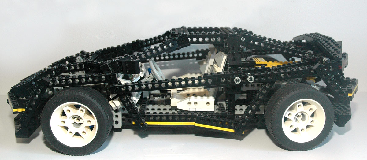
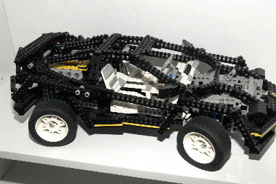
There will no doubt be some who disagree, but in my opinion this is the
first Technic set which is truly beautiful. Great care was
clearly taken in designing the exterior and interior styling while at
the same time staying true to the Technic building style and not
sacrificing functionality.
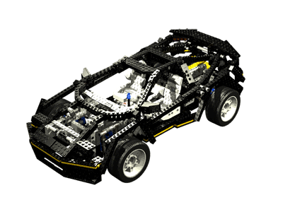
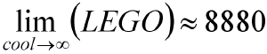
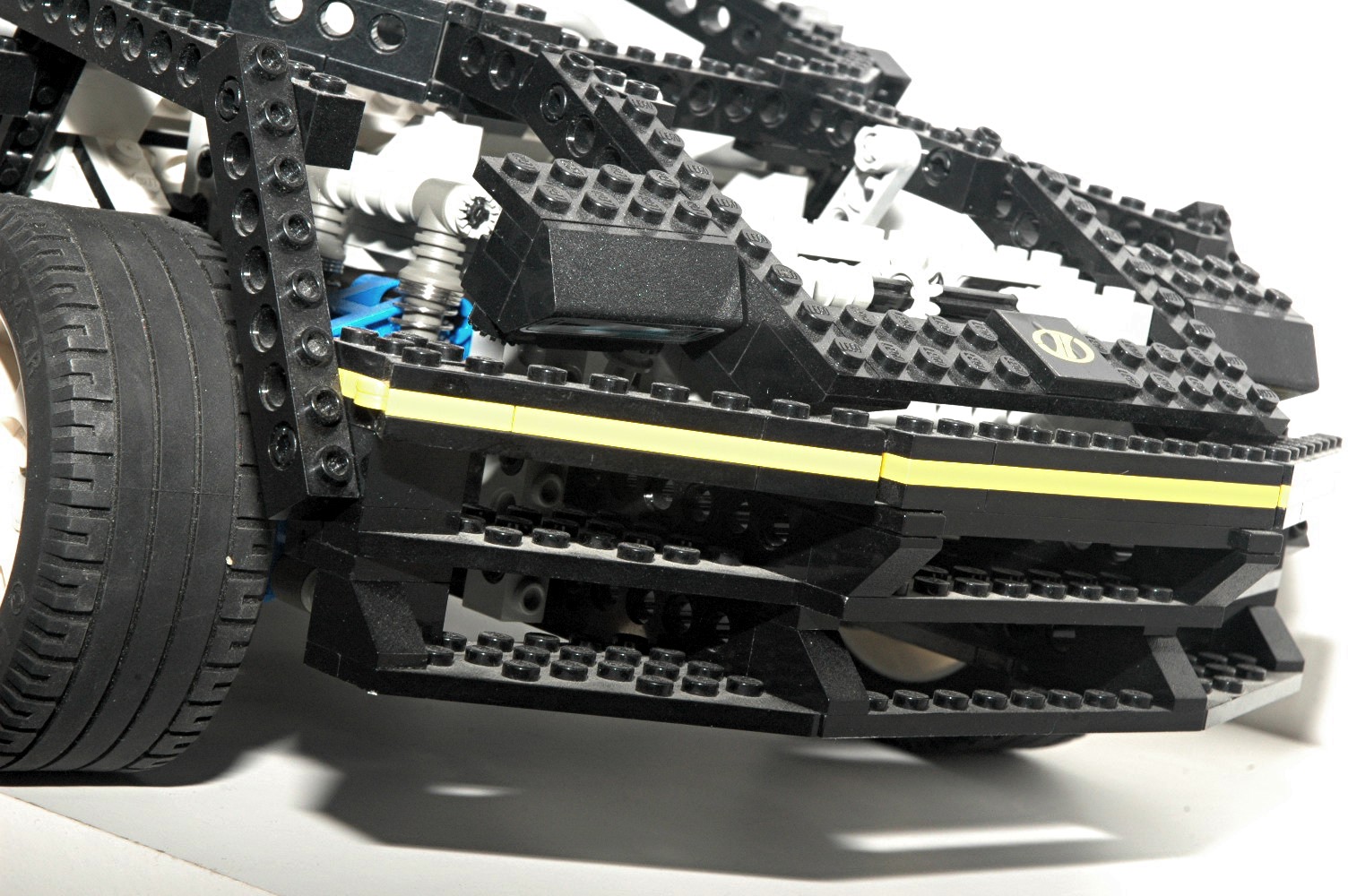
This is the first set to include a large number of stickers to augment
the styling. There is a Technic badge on the hood, a Technic
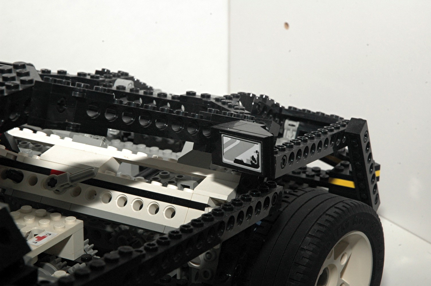
"4x4x4" logo on the back (pictured), a pair of side mirrors, an
instrument package, and labels for the gears on the shift lever of the
transmission.
Click the link to see a high resolution animation of the car from all
angles allowing inspection of all the details.
|
Click for a high resolution
rendered
animation of the Super Car from every angle.
(1150x780, 11 Mb)
|
|
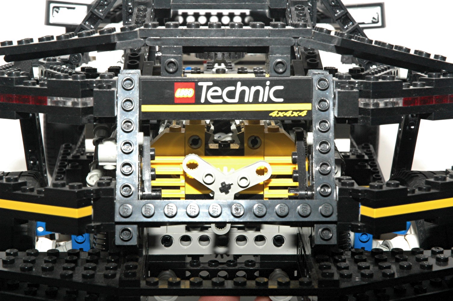
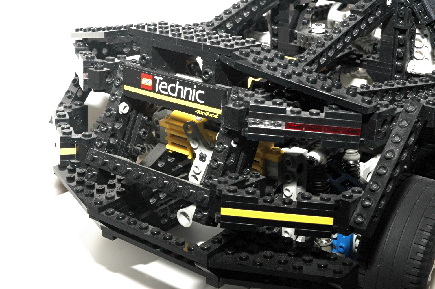
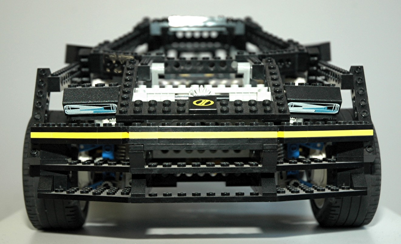
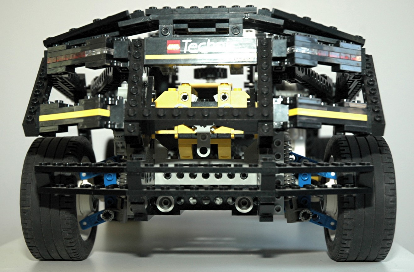
Ground Effects
Both the front and rear of the vehicle are adorned with spoilers and
ground effects.
The front bumper has a multiple level ground spoiler beneath the
concealed headlights.
The rear end has an upper air deflecting spoiler as well as slats
closer to the ground. There are also a set of transparent red
taillights and even white reverse lights. The vehicle's dual
exhaust tips are also visible in this area.
|
|
|
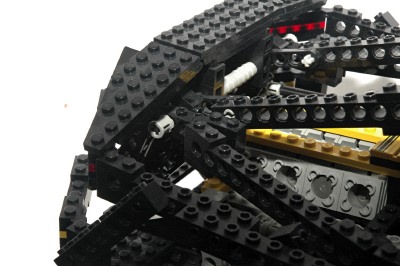
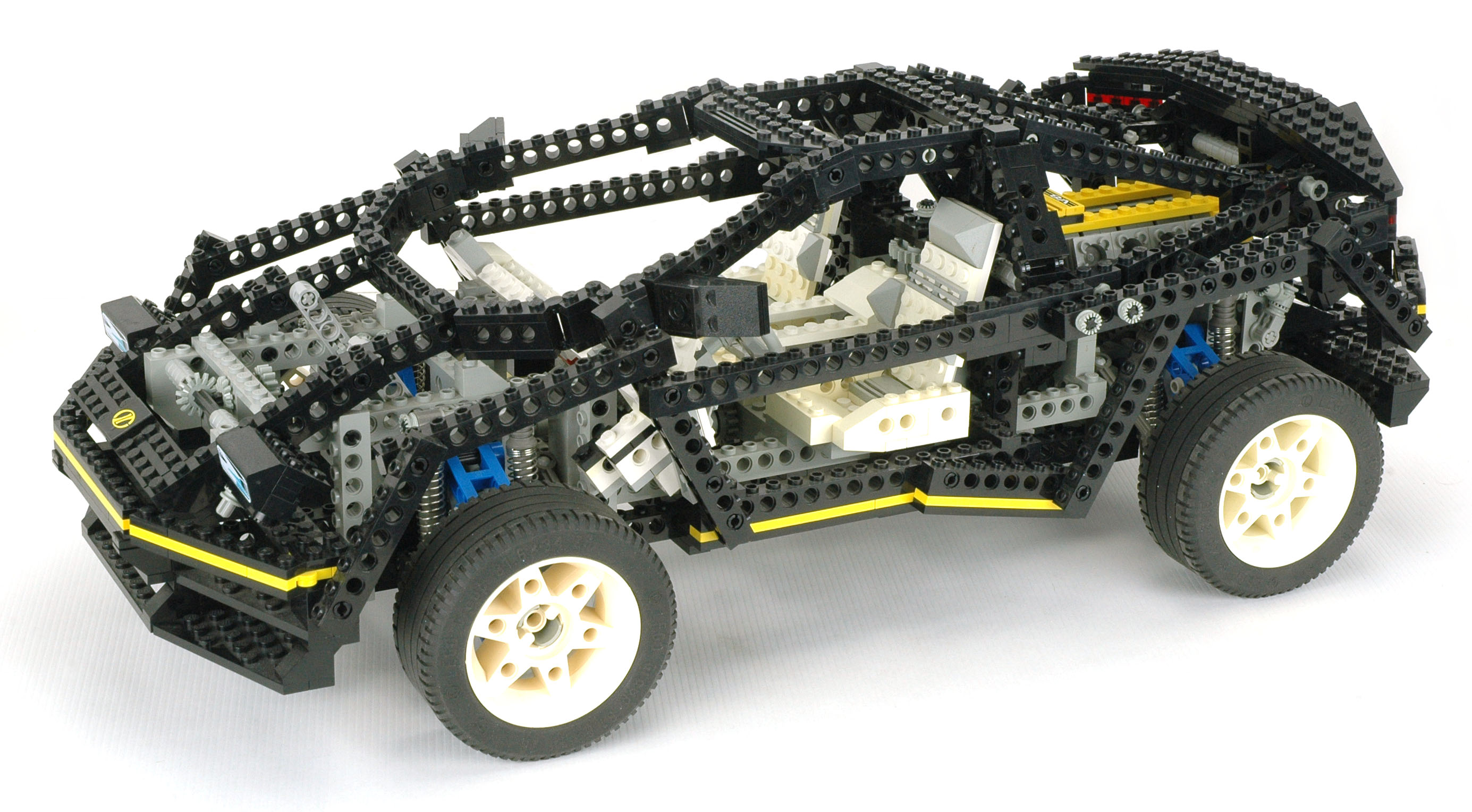
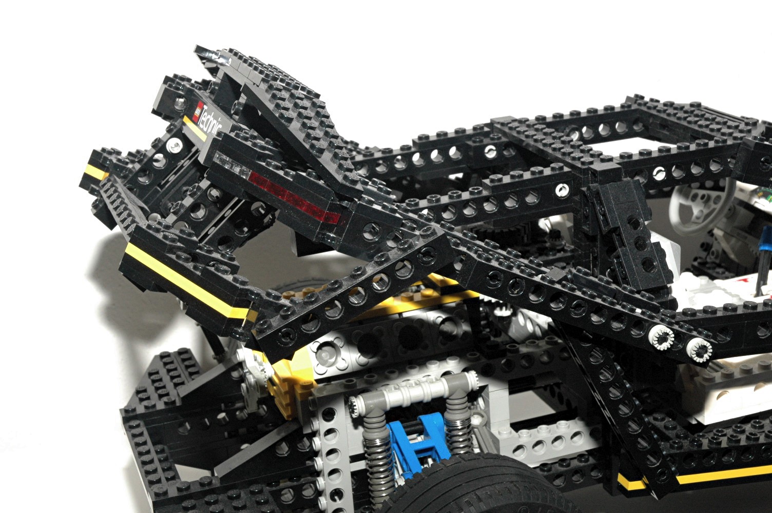
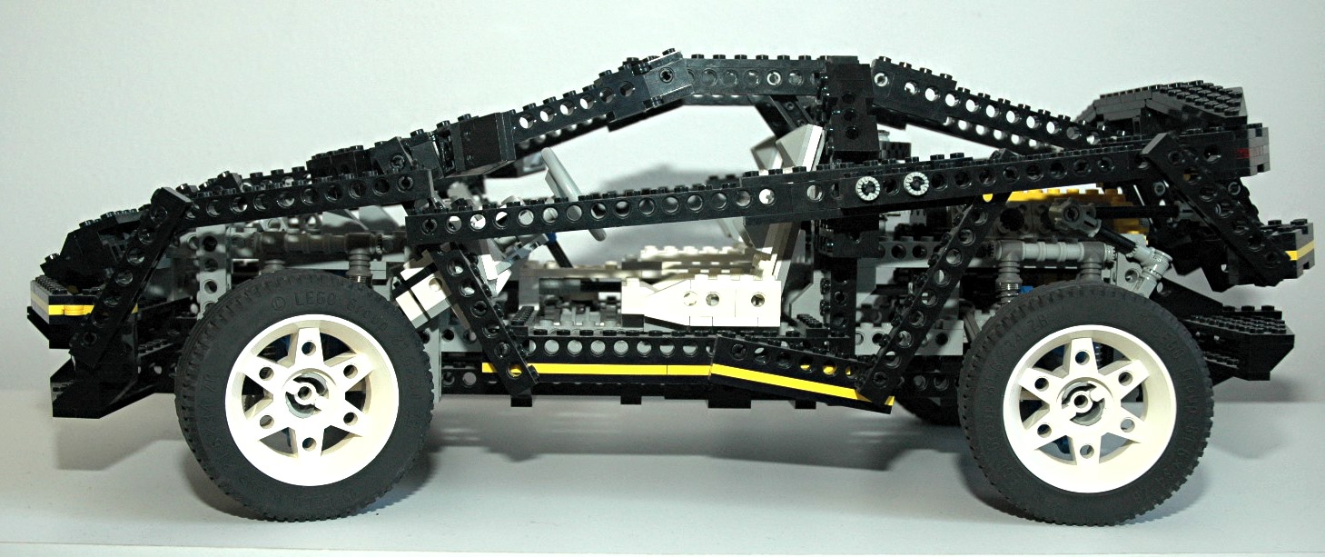
Hinged
Construction
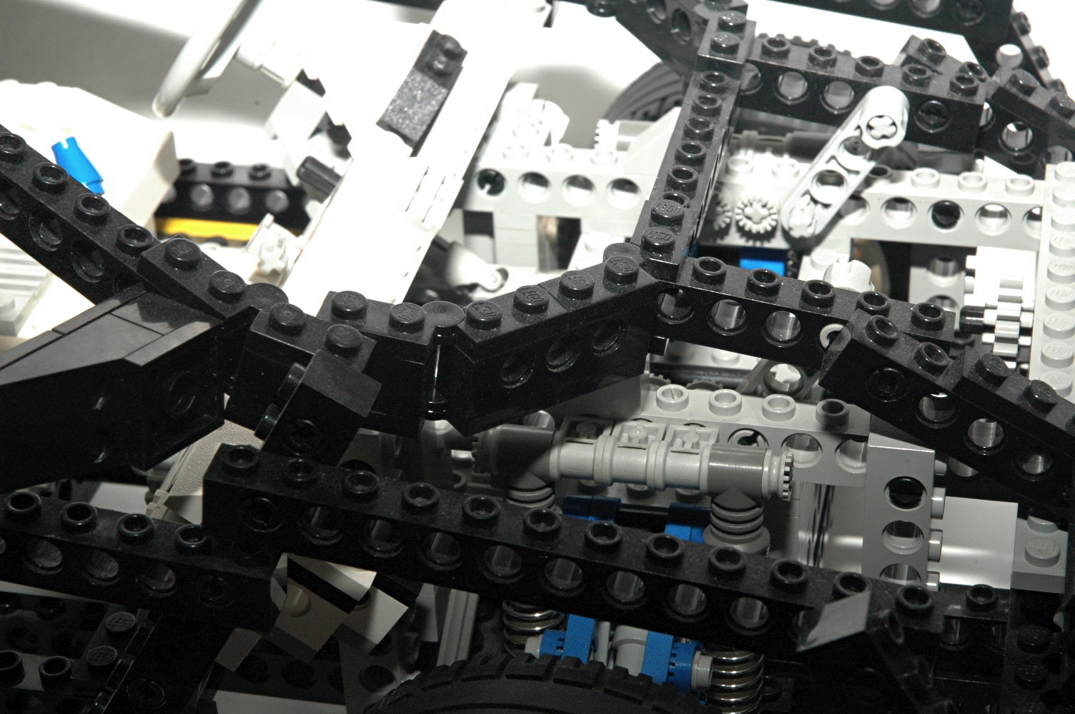
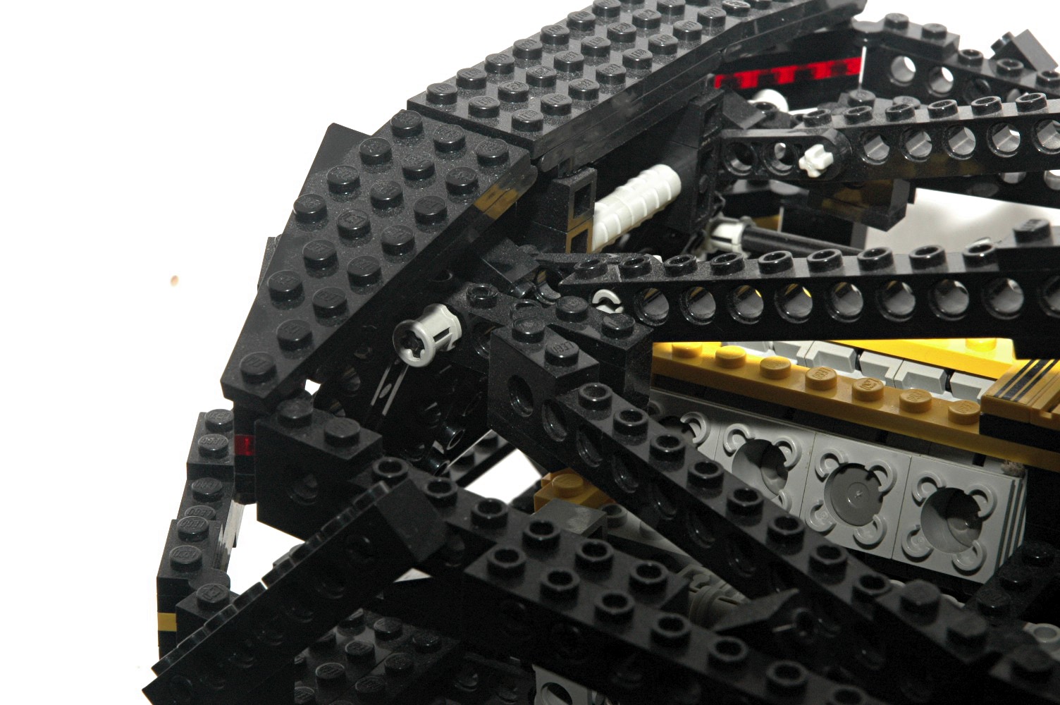
Though the body presents the illusion of complex compound curvature, it
is in fact comprised entirely of straight lines built up from Technic
beams. Angles are achieved in some places with pinned joints, but
in most cases they are achieved with 1x4 hinge plates. The images
at the right show a small sampling of these. In total, there are
54 sets of hinges in this set. Near the side mirror, a joint can
be seen in which 4 different beams converge. Areas of the
openable boot are even more complex.
|
|
|
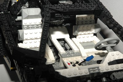
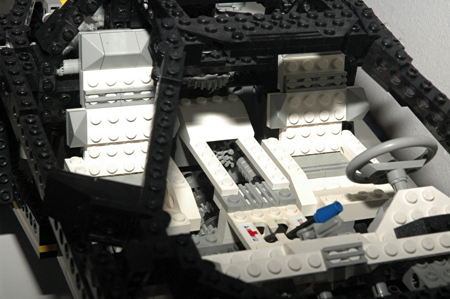
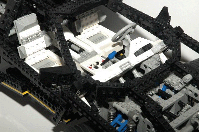
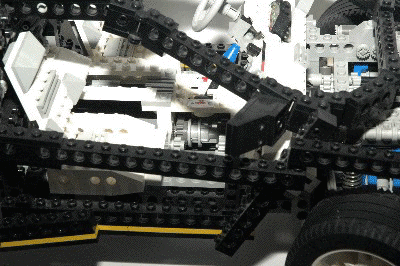
Interior
The white interior is nicely styled. There are a pair of bucket
seats with headrests and lumbar support. A center console and
armrest contain the gear shift lever. There is a lever on the
dash to control the headlights and an instrument package behind the
steering wheel.
|
|
|
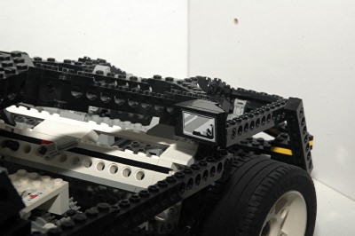
Other Details
The side mirrors can be adjusted for proper alignment and are decorated with stickers. The front headlights are concealable
using a lever on the dash. The double convex slopes used for the
lights are printed parts which are unique to this set. The
Technic badge seen in the center of the hood was first seen in this set
and became a symbol of the Technic line in years to come.
|

|
Technical Functions
|
|
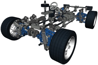
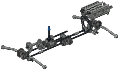
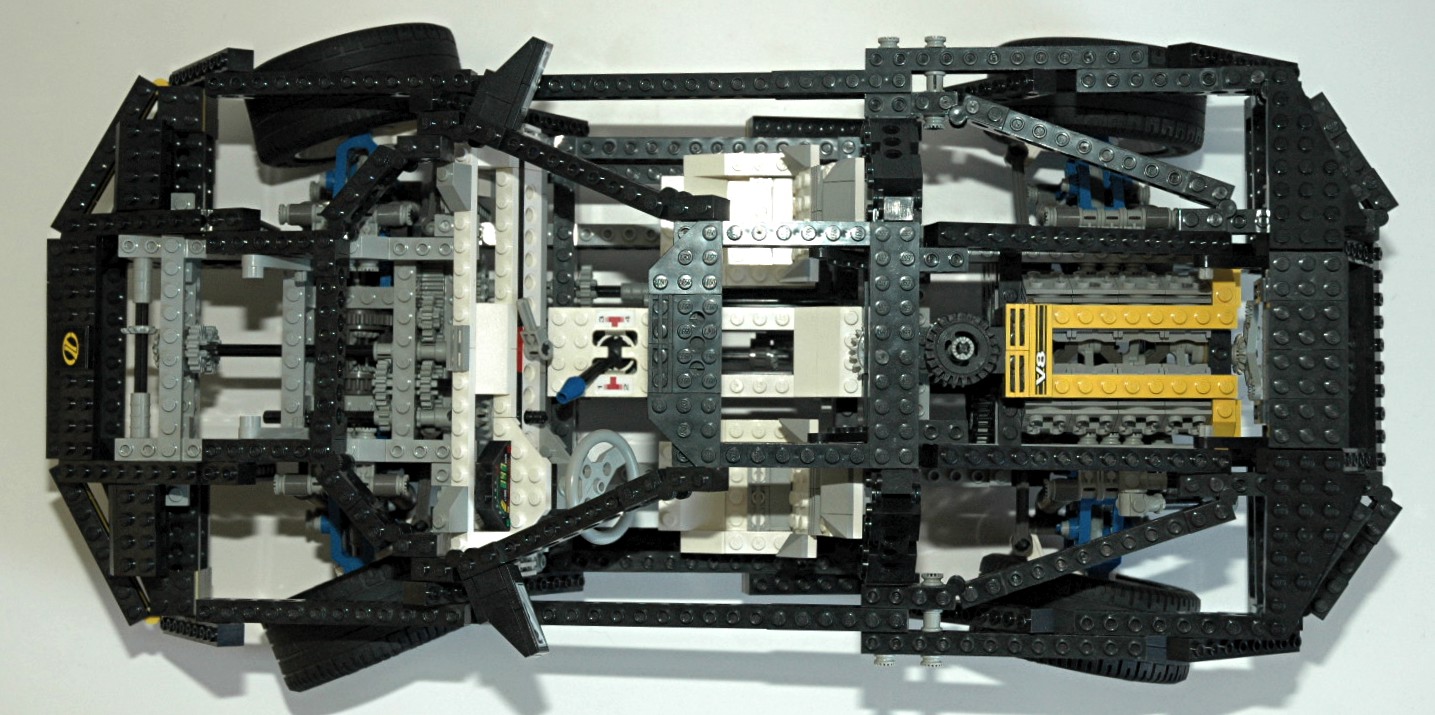
Massive
Complexity
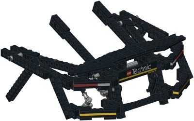
So underneath all that attractive exterior, just how complicated is
this thing? The images at the right show what the car would look
like with all the structure stripped away. To put things in
perspective, here are some statistics:
- 3 differentials
- 51 gears (spur, pinion, crown, bevel, clutch)
- 4 gear racks
- 8 shock absorbers
- 8 pistons
- 22 chain links
- 85 axles
- 13 parts not found in any other set
|

|
|
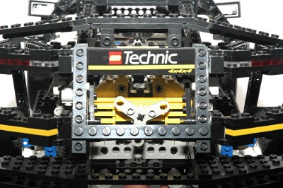
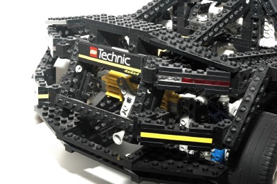
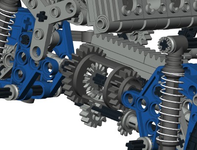
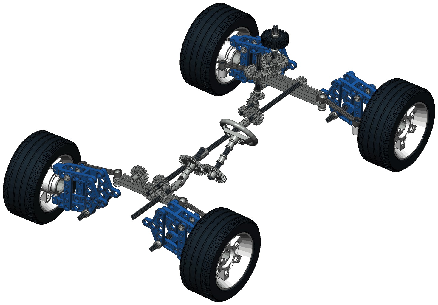
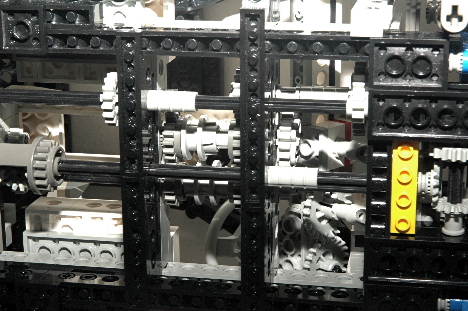
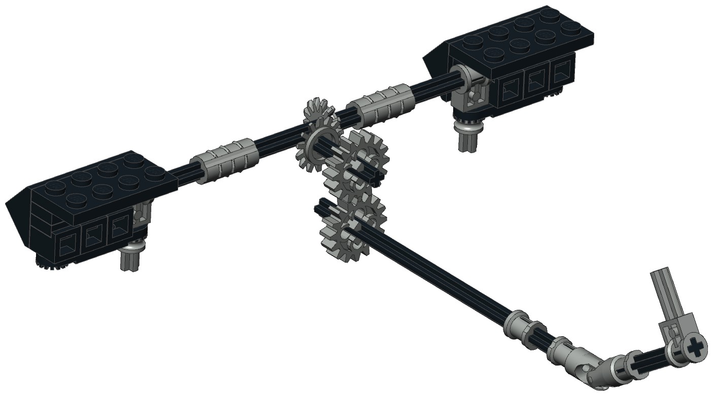
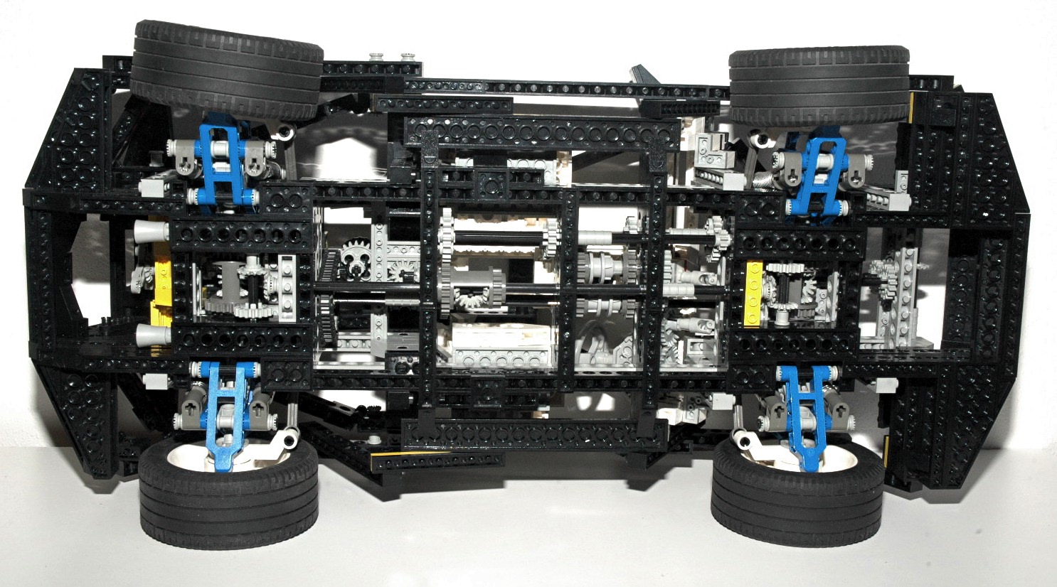
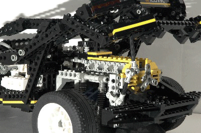
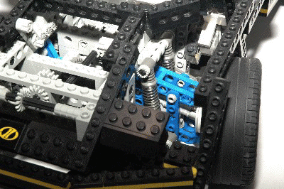
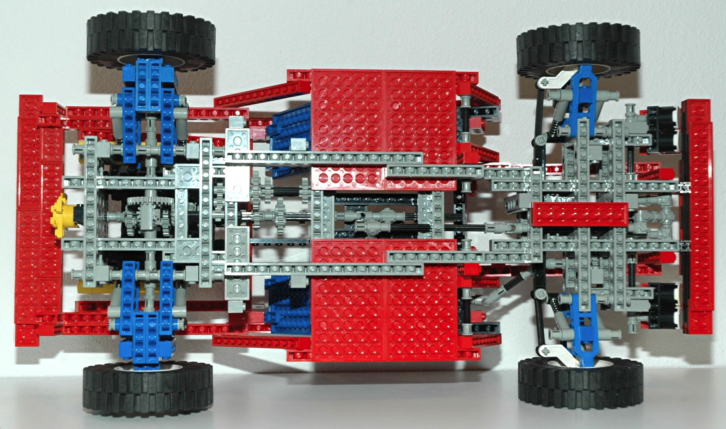
Drive Train
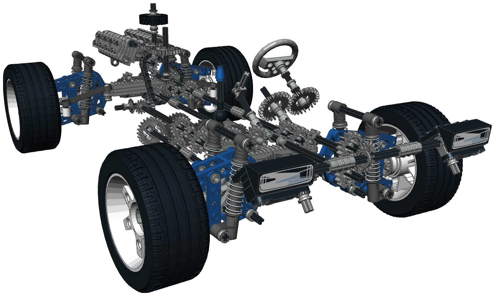
The complexity of the drive train of 8880 is unrivaled in any Technic
set. As can be seen in the computer image below left, there are 3
differentials creating a fully functional all wheel drive system.
The center differential is coupled to the 4 speed transmission which
then connects to the engine. This latch connection actually
passes through a chain loop to allow the rear steering mechanism to
pass through the center. Finally, there is a V-8 engine
mounted in the rear.
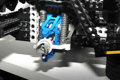
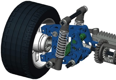
The real magic here is that each wheel has independent suspension,
steering, and is driven. Any one is easy, any two are not too
hard, but all 3 required some customized solutions which can be seen in
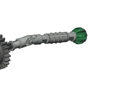
the lower right hand animation. At each corner of the vehicle is
a ball gear (shown in green), the same as those previously used as part
of a helicopter cyclic in 8856. The
yellow hub surrounding this is unique to this set. There internal
hemispherical teeth within this hub which engage the ball gear.
Because the gear is spherical and so are the teeth, the hub can rotate
up and down as the suspension moves and side to side as the steering
moves, all while retaining a rotational connection to the axle.
A custom steering arm (shown in red) surrounds the hub and acts as a
bearing. The blue control arm attach via king pin ball joints
forming a 4 bar linkage. This again allows both suspension travel
and steering. The ball joint on the end of the steering arm
connects to the steering link and rack. Finally, the white wheel
snaps over the hub. The tabs on the hub lock the wheel rotation
to that of the hub.
The is an excellent system. The only real weakness is that the
"bearing" between the hub and the steering arm has an unlubricated
sliding surface so it is prone to high friction under load.
|
|
|
Steering
All 4 wheels can be steered using a "hand of god" wheel located
inconspicuously behind the seats. This wheel turns a set of 24
tooth spur gears and then a set of 14 tooth bevel gears. Next a
set of 8 and 16 tooth spur gears increase the mechanical
advantage. The subsequent axle runs all the way forward and all
the way back to a pair of rack gears. The rack uses ball joints
at each end to attach to tie
rods. The tie rods connect to the steering arms with more
ball joints. The steering arm itself pivots on upper and lower
king pins which fit into sockets in the control arms.
Note that the forward rack uses a 16 tooth pinion and the back rack
uses an 8 tooth pinion. This results in the front wheels turning
more than the back wheels. Note also that wheels turn in
opposite directions, pointing to a common center of the turning circle.
In this Technic set, the steering employs the
Ackerman Principle based on the shape of the steering arms.
You can see in the images that the tie rod attachments are not directly
behind the kingpins, but are
inboard. The result of this is that the wheel on the inside of
the turn is rotated more sharply than the wheel on the outside, which
is exactly what is required for a turning in a proper circle without
skidding.
Finally, there is a second parallel gear set which run back from the
front rack, through a u-joint, to the steering wheel in the
cabin. This allows the steering wheel to follow along with the
wheels, or even for the steering to be driven from inside.
|

Click for an animation of the
steering in motion.
|
|
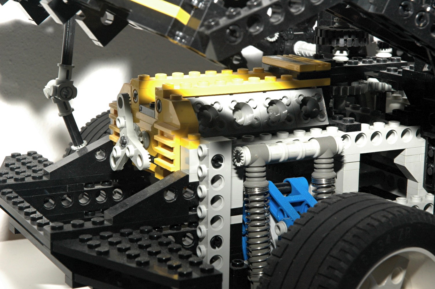
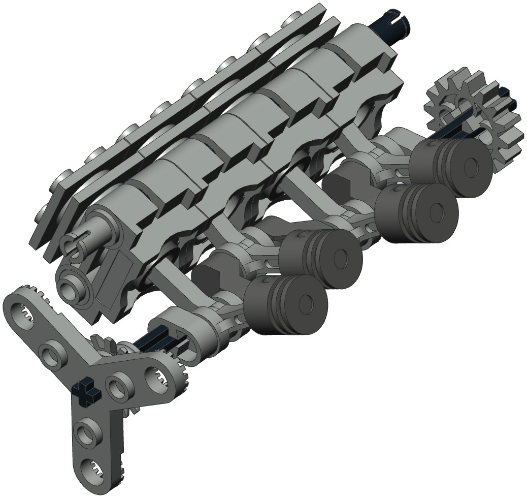
Engine
This set features a rear mounted V-8 engine with a 90 degree V
angle. This is the first Technic engine to have 8
cylinders. The engine is made from cylindrical engine elements
and is located above the rear differential behind the seats. It is
driven by the all 4 wheels.
The crankshaft is
offset 1/2 stud from center, giving the pistons a stroke of 1
stud. The crank has 4 crank pins at 180 degree angles. Most
V-8s have crossplane cranks with the pins at 90 degrees. While
many racing V-8s do indeed have flatplane cranks like this LEGO
version, they are always 0-180-180-0 instead of 0-180-0-180.
The engine also has a number of aesthetic features such as an intake
manifold and a 3 blade fan..
|

Click for an animation of the
engine
in motion.
|
|
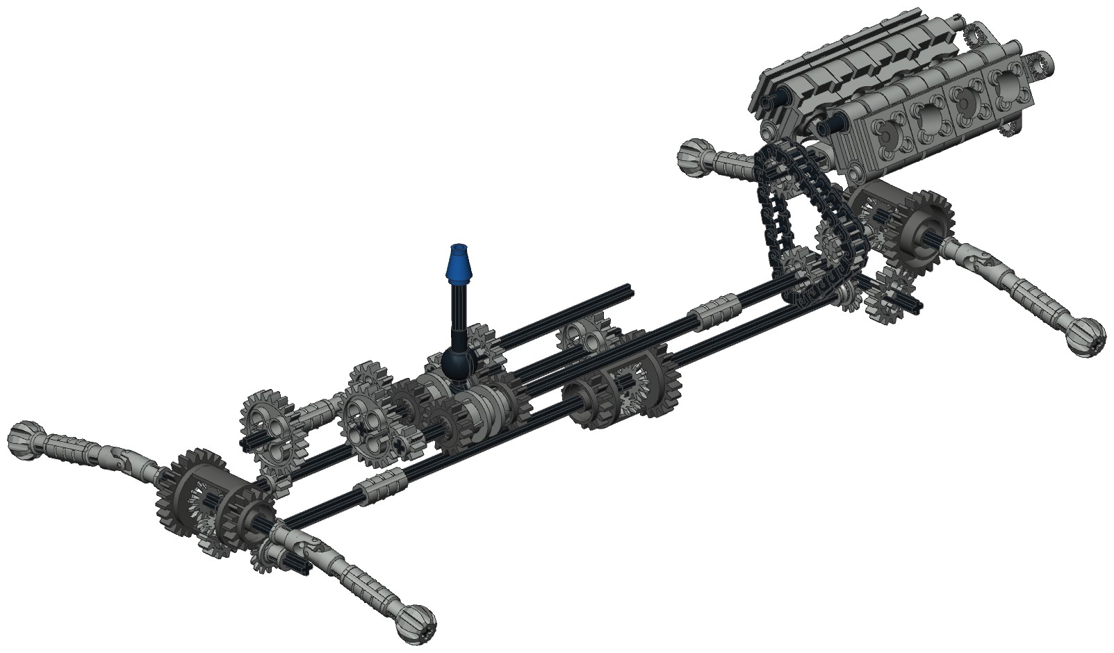
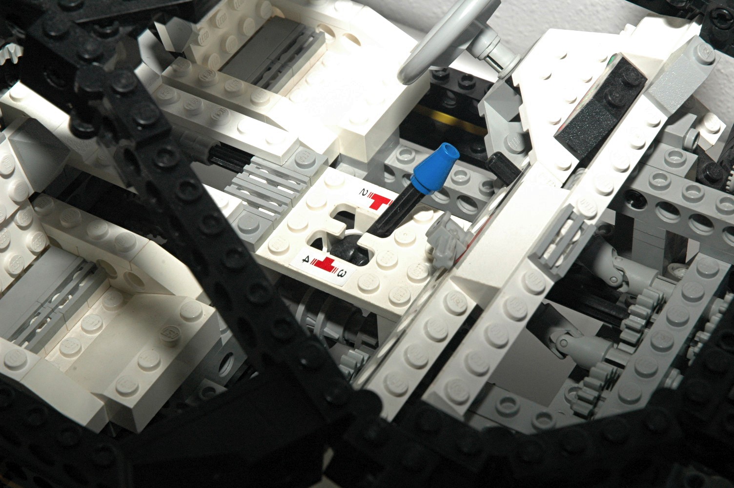
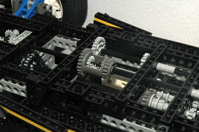
Transmission
Ahead of the engine, attached via a chain loop, is a 4 speed gearbox /
transmission. Unlike previous auto chassis transmissions, this
one does not need to be aligned to shift and can even be shifted while
rotating.
The first photograph shows the shift lever and gate with the 4
positions. As the lever is moved through the H-shaped gate, one
or the other of the two driving rings is forced into position.
Note that only one driving ring can be engaged at a time. Passing
through the center of the H returns the opposite ring to center.
The new driving ring is the key to everything. It slides over the
ridged axle joiner
which we first saw in 1993. Small tabs on the driving ring allow
it to lock along these ridges, but still slide with some extra
force. The driving ring grips the longitudinal grooves on the
axle joiner causing them to rotate together. A circumferential
groove in the middle of the ring allows it to be pushed along the axle
joiner in either direction. A set of 4 driving dogs on either end
then mate with a 16 tooth idler gear allowing the idler's rotation to
be either synched with the axle or allowed to spin freely.
The animation shows how the new driving rings work to engage and
disengage the clutch/idler gears. The driving ring is shown in
red. The
lower axles are joined with the gray axle joiner. The driving
ring rotates with the axles. At first, the driving ring is
disengaged so both the dark gray and green gears are not driven and
slip on the axle. The driving ring then engages the green gear
and
thus drives the blue gear. Because the driving ring does not use
gear teeth but
rather uses four tapered driving dogs, there is considerable backlash
between the driving ring and the gear. The allows the driving
ring to be engaged even while it and the mating idler gear are turning
at different speeds.
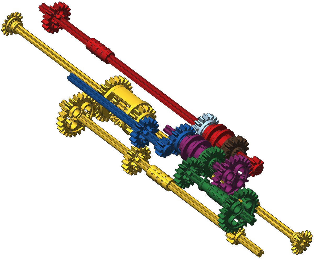
The lower left computer image is color coded to show the different
gears paths for each of the 4 gears. The red parts go to the
engine. The yellow center differential is the output to the
wheels. You can see that the yellow axles interface with
the other gears in two places: blue and green. This means that
the blue and green axles are always turning at different rates, as are
the blue and green idler gears. The cyan idler gear turns with
the blue one, and the brown idler gear turns with the green one.
Next, note that the red engine gear is linked to the purple driving
ring. This means that the red and purple axles are always turning
at a different rate (3X). Now let's trace each of the 4 gears
starting always with the red engine axle:
- 1st Gear: (purple ring, blue gear) 24:8
(purple) x 8:16 (blue) x 16:16 (yellow) x 24:24 (diff) x 14x14 (bevels)
x 24:16 (final diff) = 2.25:1.
- 2nd Gear: (purple ring, green gear) 24:8
(purple) x 16:16 (green) x 8:24 (yellow) x 24:24 (diff) x 14x14
(bevels) x 24:16 (final diff) = 1.5:1.
- 3rd Gear: (red ring, cyan gear) 16:16 (cyan) x
8:16 (blue) x 16:16 (yellow) x 24:24 (diff) x 14x14 (bevels) x
24:16 (final diff) = 1:1.33.
- 4th Gear: (red ring, brown gear) 16:16 (brown)
x 16:16 (green) x 8:24 (yellow) x 24:24 (diff) x 14x14 (bevels) x
24:16 (final diff) = 1:2.
Note that 3rd and 4th gears are overdrive. This would be bad for
a real car and make this model difficult to motorize. But in this
case, the engine is really meant to be driven by the wheels rather than
the wheels by the engine. This makes the reversed gear ratios
quite convenient for simply pushing the car around.
|
|
|
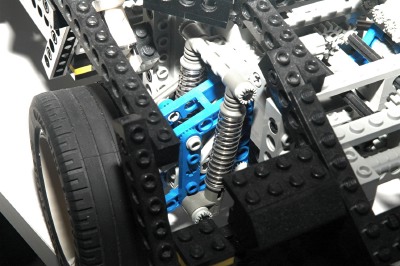
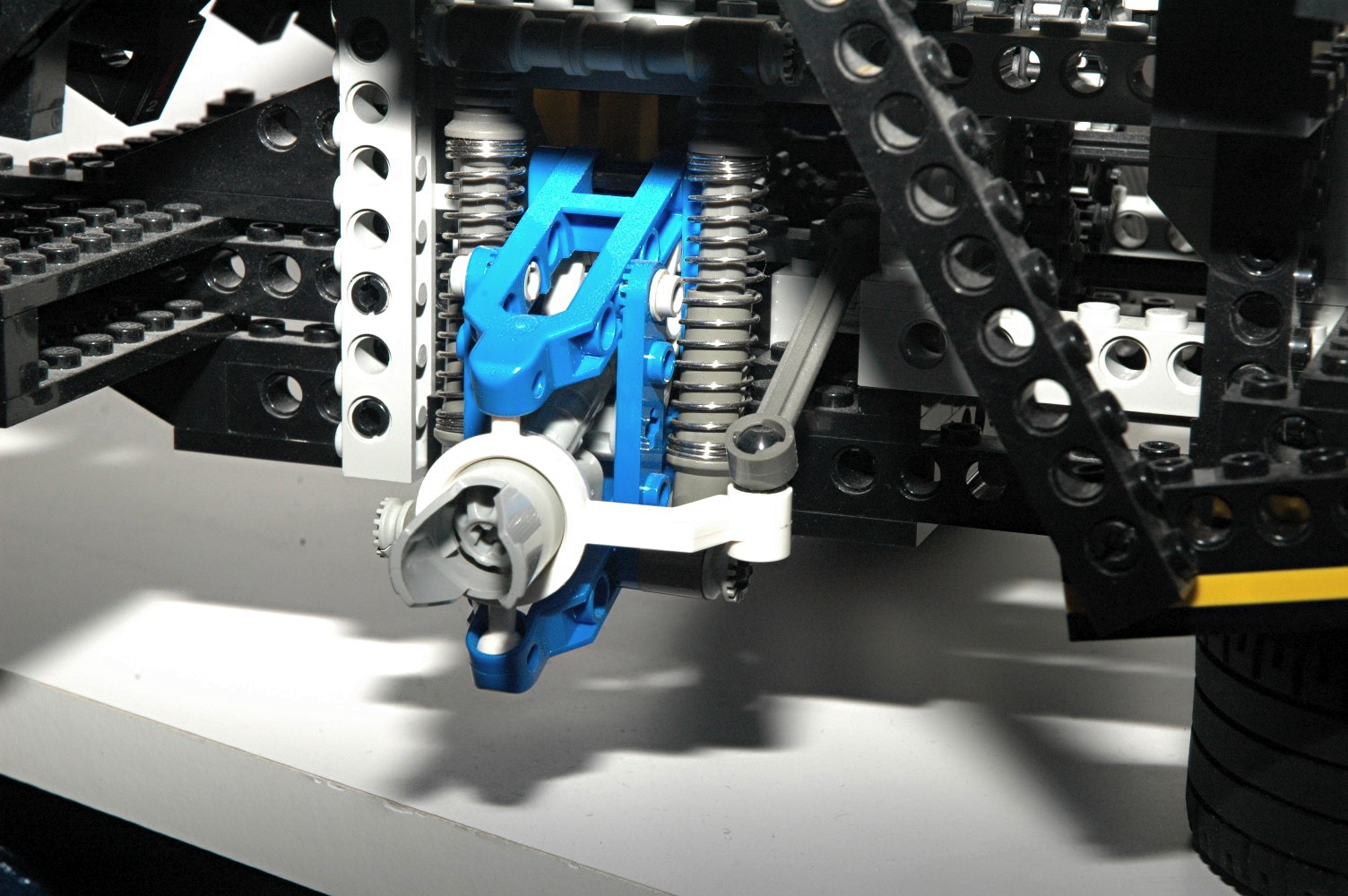
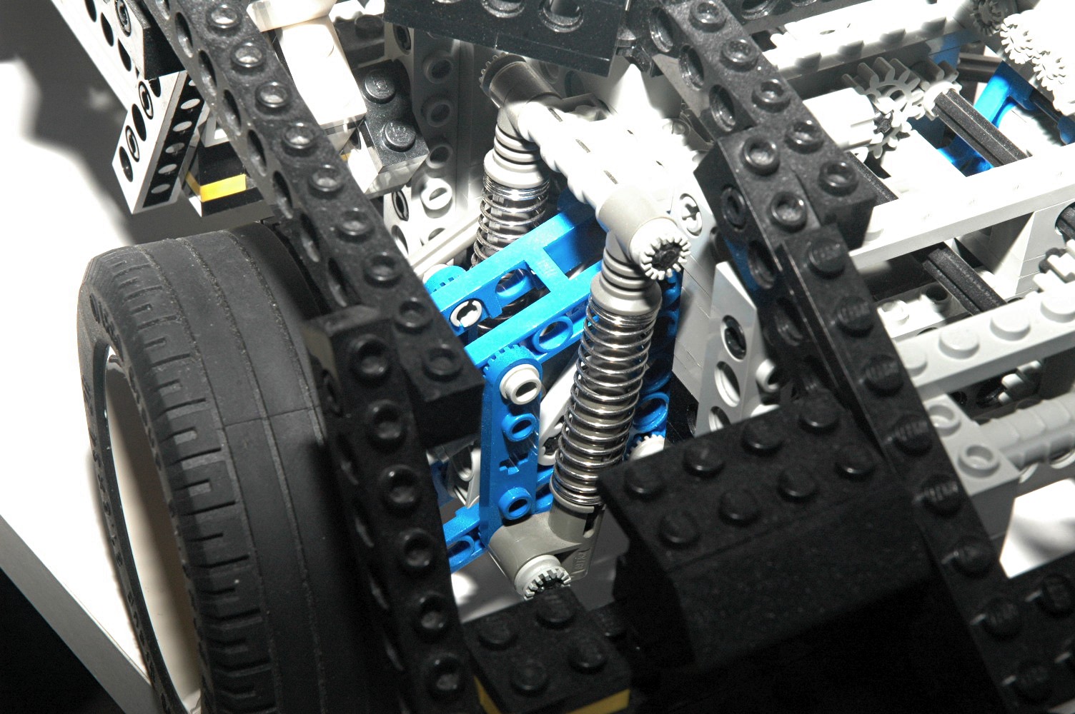
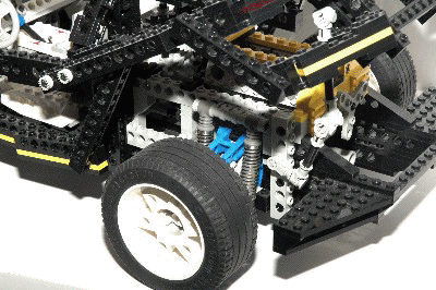
Suspension
All 4 wheels have independent suspension. The suspension uses the
control arms parts (blue) and
steering arms (white). Upper and lower ball joints form king
pins, making this a double wishbone suspension. Because it is a
four bar linkage, the wheel stays perpendicular to the ground
throughout its travel. A pair of shock absorbers provide
support.
Power is driven through a pair of
universal joints on each side. The pivot point of the u-joints is
carefully aligned with the pivot points of the suspension so that the
axles need not change length.
The parts shown in green in the computer image form a suspension travel
stop which limits the range of the suspension to a very small
value.
I'm not entirely sure why this was done as I find the model more
enjoyable with them removed.
The suspension in this model is quite stiff and the ground clearance
quite high. Personally, I think the model looks better with the
suspension fully compressed. When extended, it looks almost like
an off-road vehicle. At the bottom of the page there is a view of the model with the suspension altered to allow
full compression.
|
Click for an animation of the
front suspension
in motion.
Click for an animation of the
rear suspension
in motion.
|
|
Differentials
This set uses 3 of the new differential gears, one each at the front,
rear, and center. Each
incorporates a built in 24 tooth ring gear which works as a spur.
It is the same geometry as the 24 tooth spur gear. Each
differential is made
to house 3 of the 14 tooth bevel gears. One is on each axle,
and one planet gear in the middle allows the axles to turn at different
rates. The addition of the center differential also allows the
front and rear wheels to turn at different rates. As these are
open differentials, it is possible for all the power to go to only one
wheel if the other 3 are locked. |
Click for an animation of a
differential
in motion.
|
|
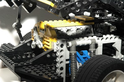
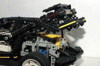
Boot
The rear "boot" (or trunk lid, or hood, depending on how you think
about it) opens to reveal the engine. The linkage geometry here
is quite complex. The bulk of the structure is pinned about a
point on the body. However, the links which represent the rear
window have a different pivot axis and even break in the middle to
avoid binding the mechanism. Finally, another pair of links go
down to some runners along the rear edge of the door sills. All of this
can be seen much more easily in the animation.
There's also a collapsible link which hold the boot in the raised
position by moving over center.
The rear structure where the sticker is attached is rather complicated
to build and easy to mess up, in which case nothing will fit and the
mechanism will bind. But when done right, it is a think of beauty.
|

Click for an animation of the boot
opening.
|
|
Headlights
The concealed headlights are comprised of double convex printed slopes
which can be opened via a lever in the cabin. Rotation of the
lever turns a u-joint which drives through a set of 16 tooth spur gears
and then a set of 14 tooth bevel gears. Total rotation of the
light axis is about 135 degrees.
|
|
|
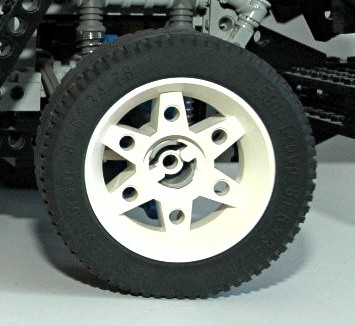
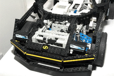
Wheels and Tires
The wheels are enormous, wide, and flat. Only two
models ever used these wheels, and only this model ever used the center
locking ring. They are labeled 81.6 x 34 ZR. |
|


